Stabiliser Elevator
With all the parts located for the stabiliser
/ elevator
and the plans pinned to the the building table and covered with plastic. The
trailing edge is located and pinned over the plan. Next the centre balsa section
parts are located.
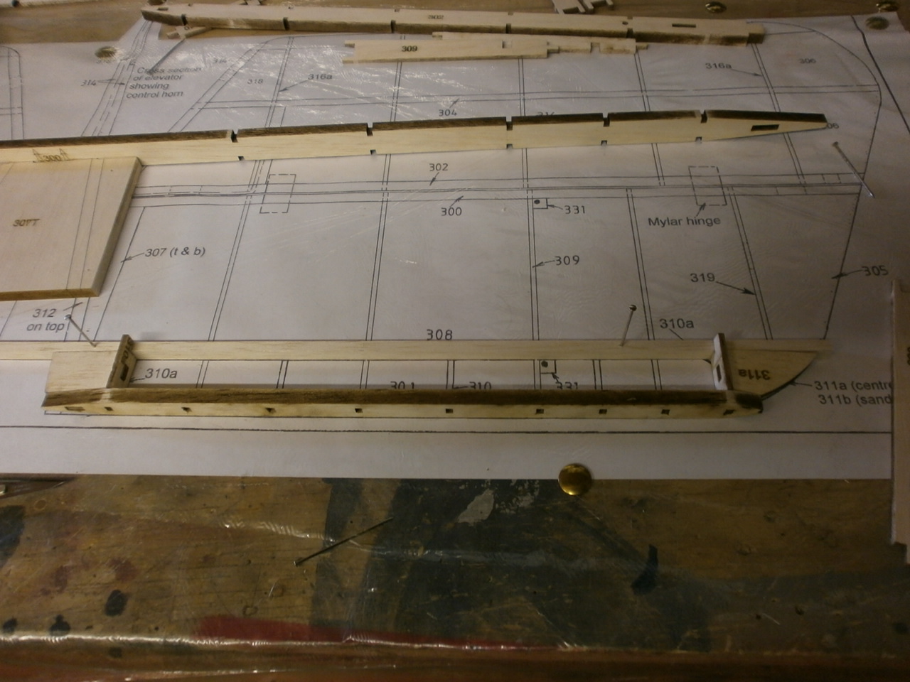
There are two pieces that make up this part which need to be laminated together.
Once this has cured it is offered into its position on the plan. This part has
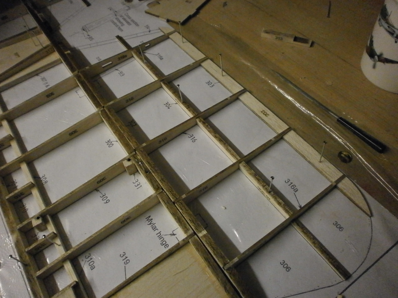
to tabs that neatly locate into the trailing edge piece. See picture 1
Also in picture 1 below you can see that the leading edge piece is located over the plan. In the instructions it tells you to glue in the 310a riblets and both end pieces . At this stage we decided to dry fit everything into place so decided to ignore this instruction.
Also in picture 1 you can see the 1/4x1/4 main spar which has also been pinned to the plan.
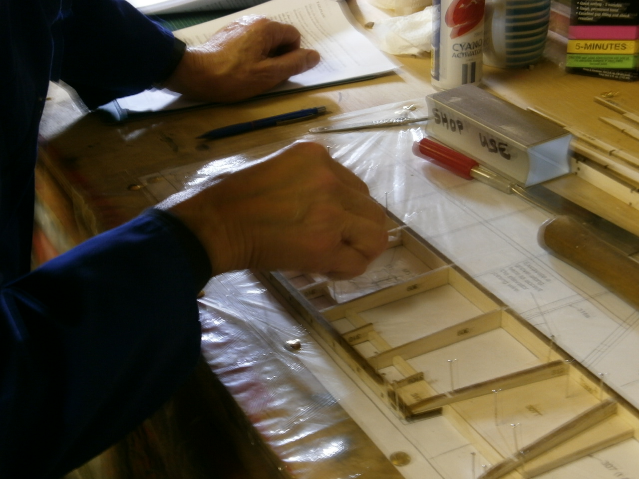
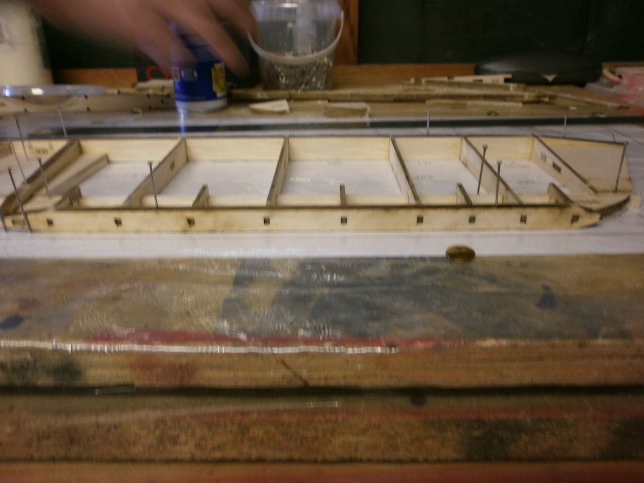
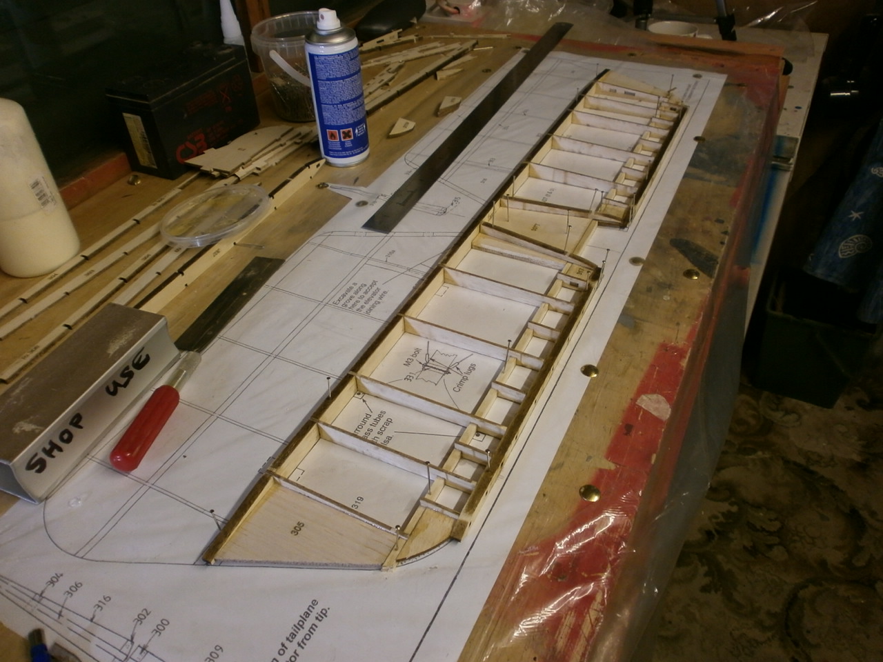
The 310 riblets and the 309 ribs are located from the pile of bits and fitted, first to the leading edge and then the whole assembly offered and interlocked into and onto the main spare and trailing edge. See picture 2 below.
|
|
|
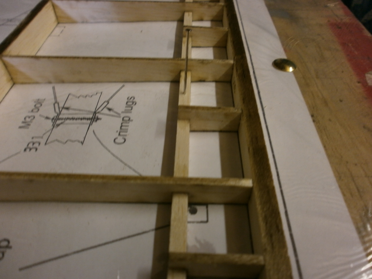
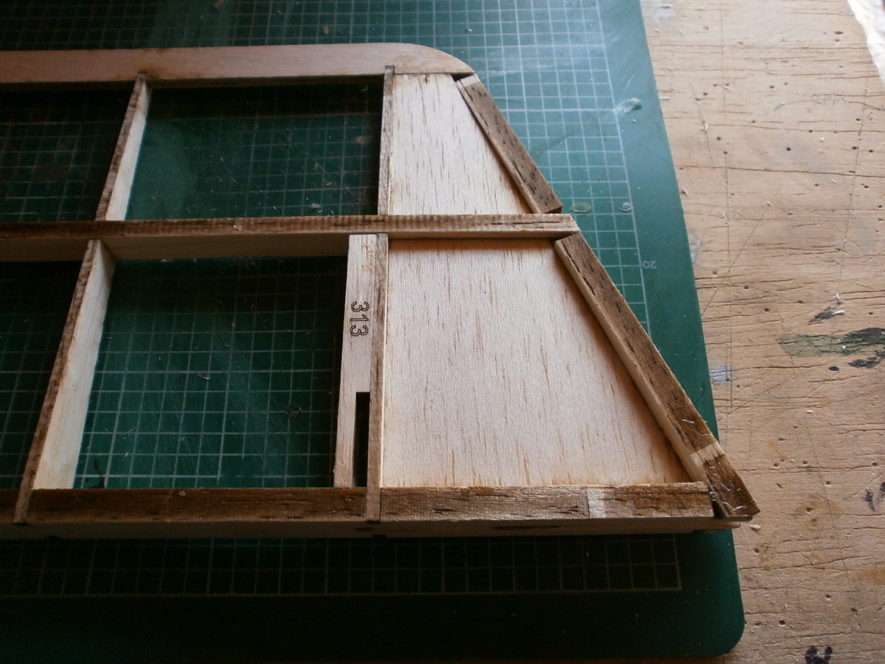
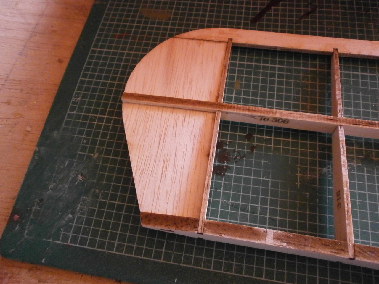
The next picture shows a close up of all the parts mentioned above now in place.
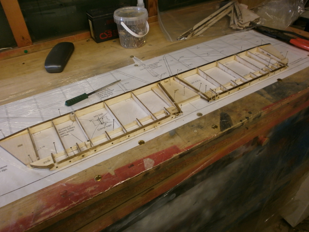
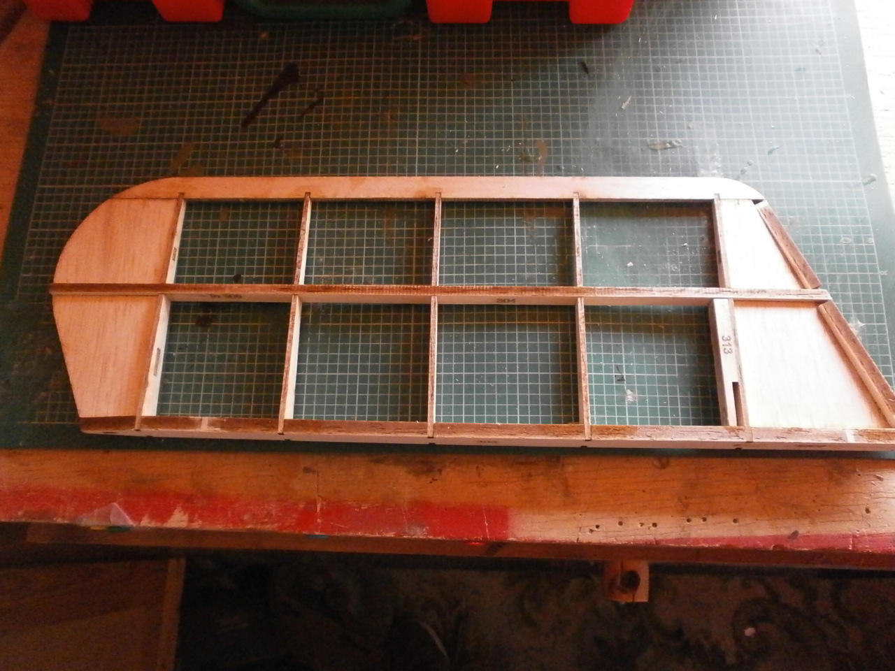
Picture 2 below showing the whole Stabiliser structure now made up ready for gluing. Note also the stabiliser tips now in position.
 |
 |
Picture 1 below showing the laser cut leading edge with the notches cut out with the now installed ribs and riblets in place.
One we where happy with the fit everything is glued up, again using super glue. See picture 2
 |
 |
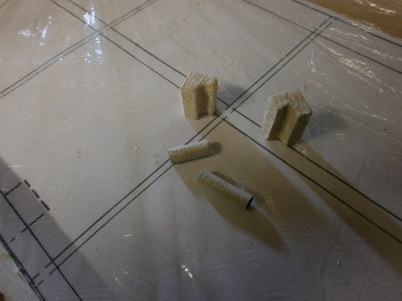
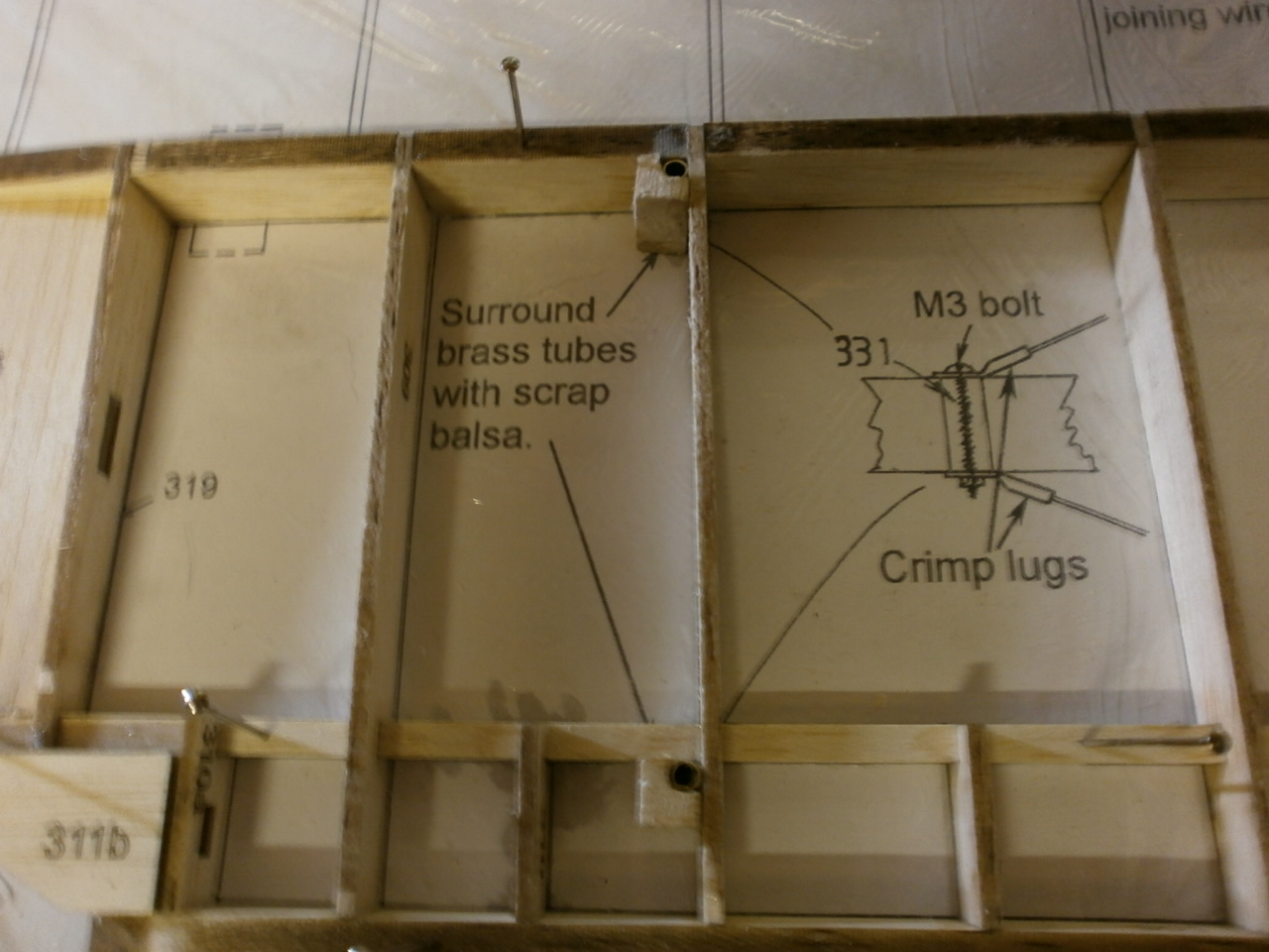
With the stabiliser all glued up we moved our attentions to the task of making up the elevator / rudder brace mountings. These consist of brass tube rapped in masking tape as we did for the wing locators. See picture 1
These are then glued into there locations and reinforced with scraps of balsa. See picture 2
 |
 |
This is as far as we are going with the stabiliser at
this stage as all that is really left to do is to sand the structure to its
final profile before cov
ering.
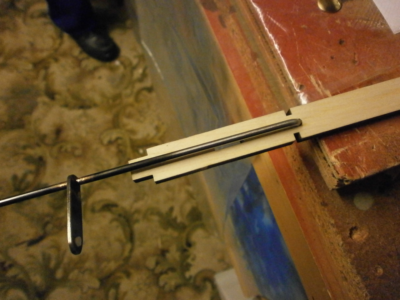
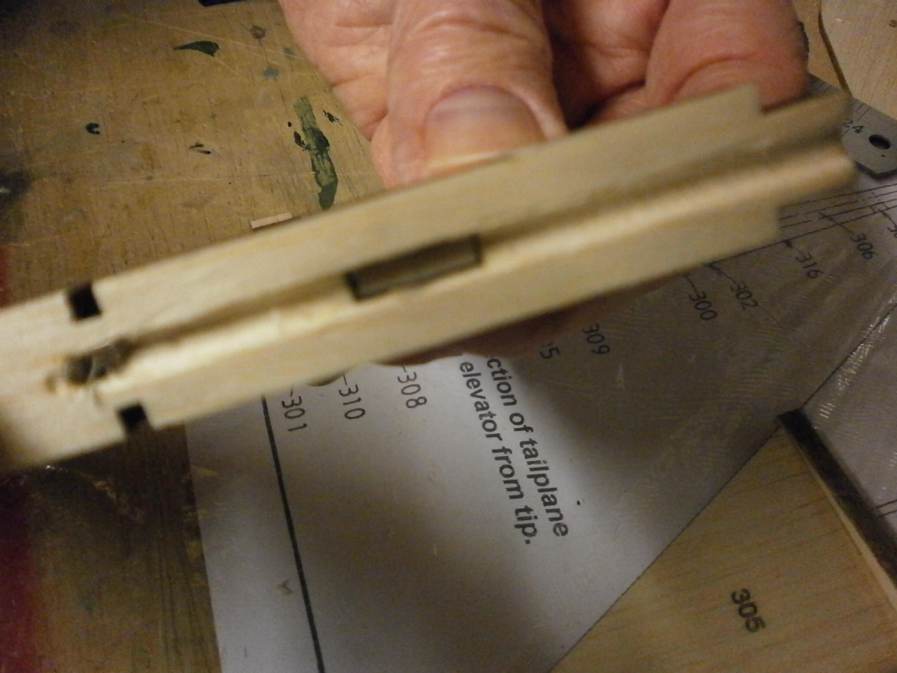
Nest on the agenda then is the elevators. The first thing
here is to locate the leading edge pieces of each half along with the wire
joiner / horn.
This is then offered into the locating hole and marked along either side
making sure that everything is maintained square. Pic1,2 below
 |
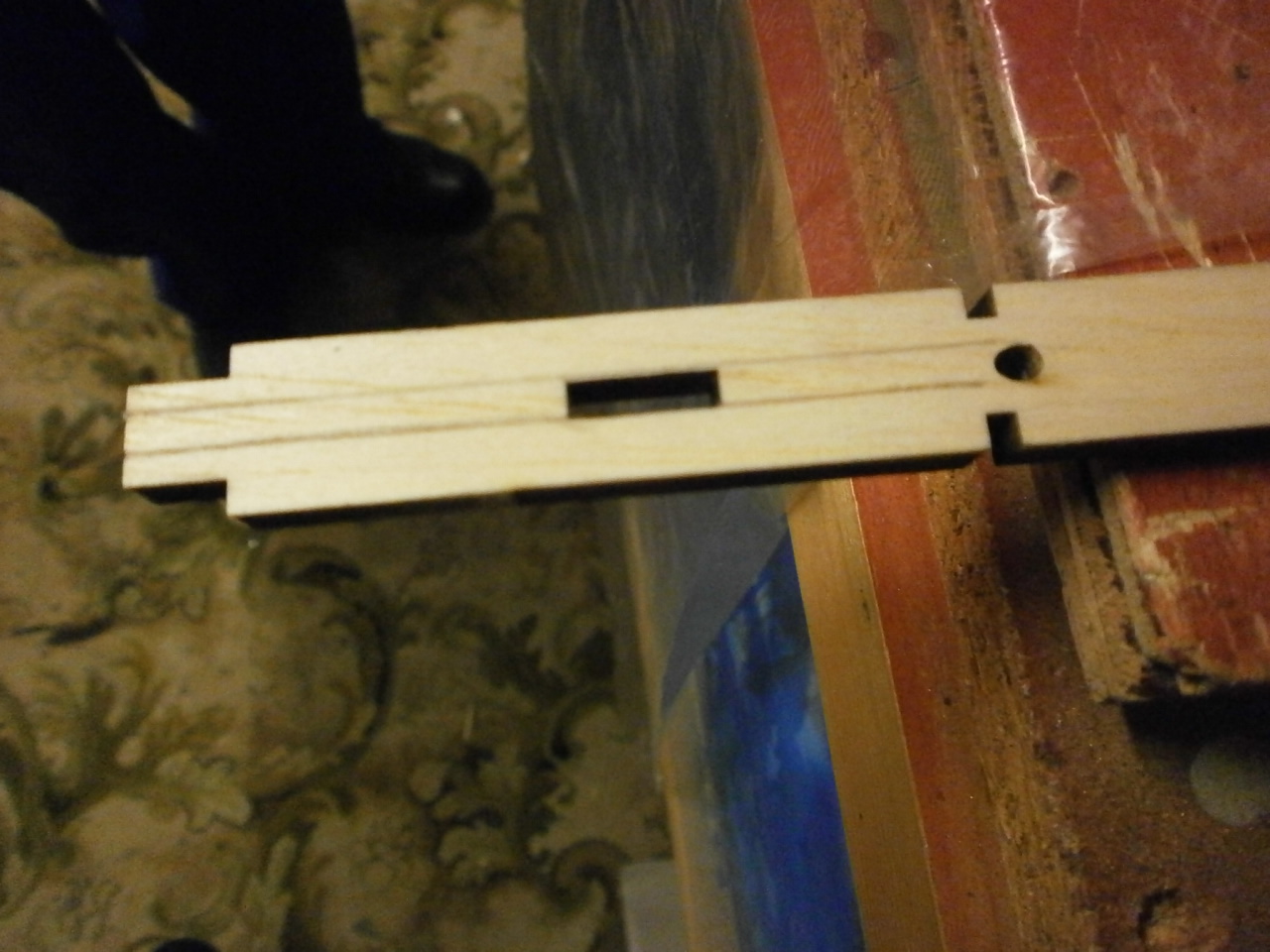 |
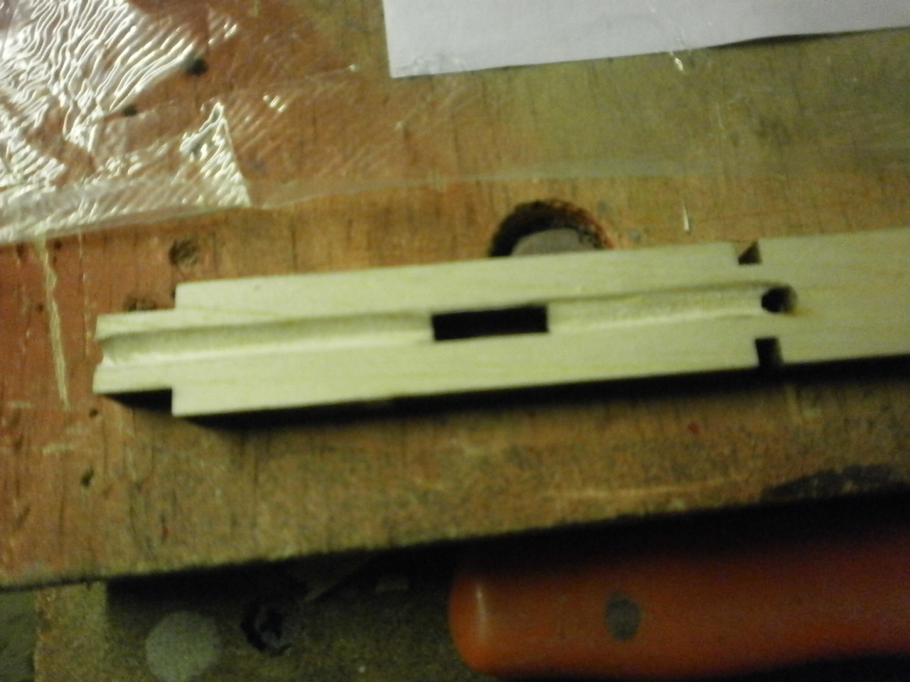
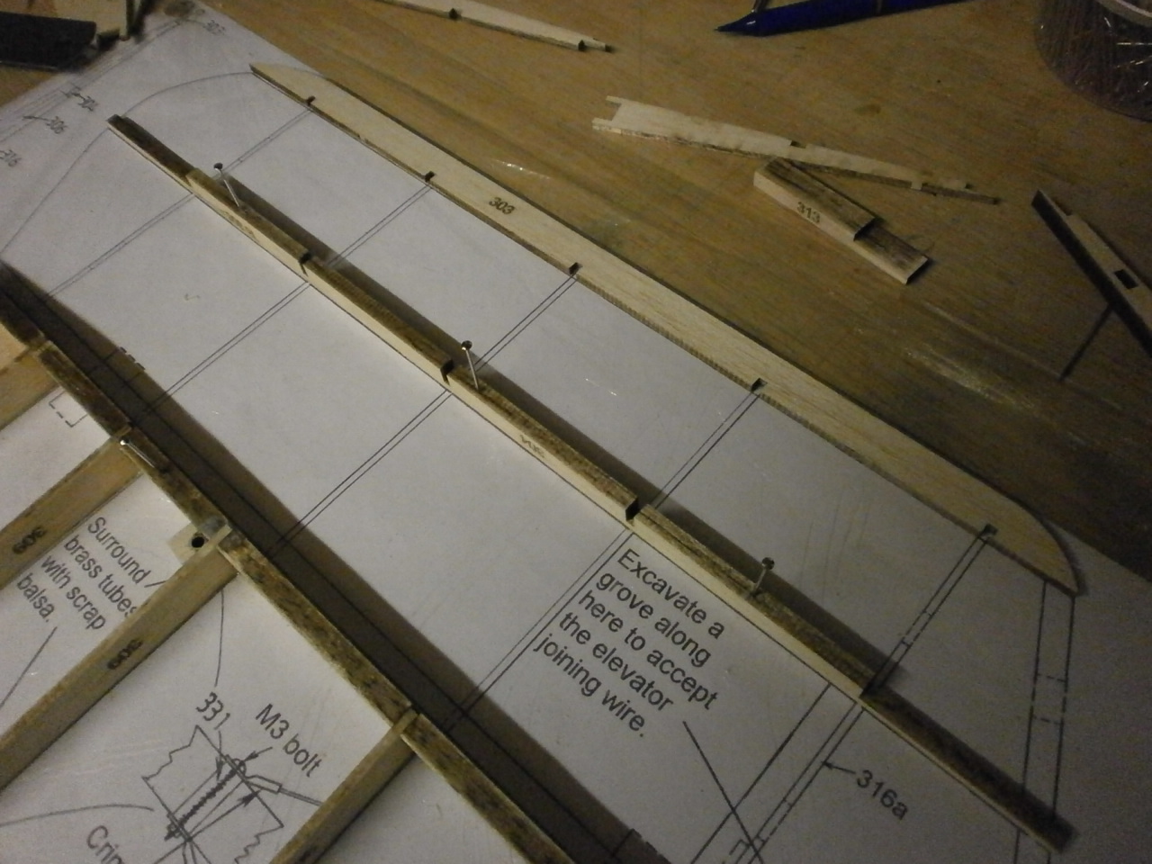
Once marked a grove needs to be cut along the marks to the depth of the piano wire ensuring it sits flush with the top of the leading edge. This was done by first runing a craft knife along each marked side at about 45 degrees. Then the waste is removed leaving a v groove. This is then rounded out using a drill bit the same size as\ the piano wire by running it along the groove until it becomes curved. Picture 1 below
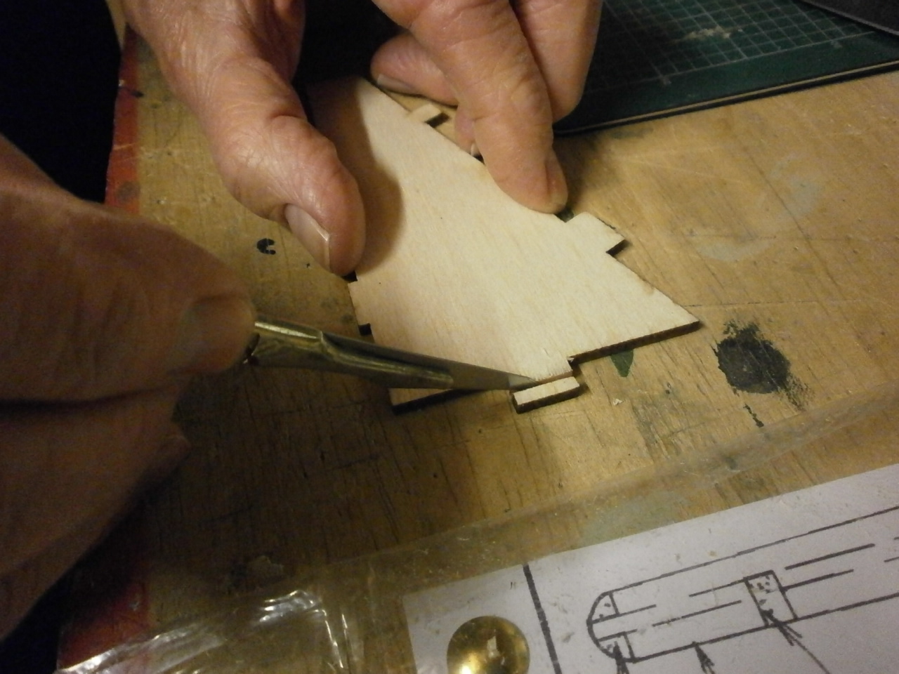
The Second & third picture showing the inner tip having the locator tab partially removed, enabling it to be located into position where the groove has previously been placed and so allowing uninterrupted placement of the piano wire joiner.
 |
 |
The trailing edge and centre spar are now placed over the plan and pined into place.
 |
 |
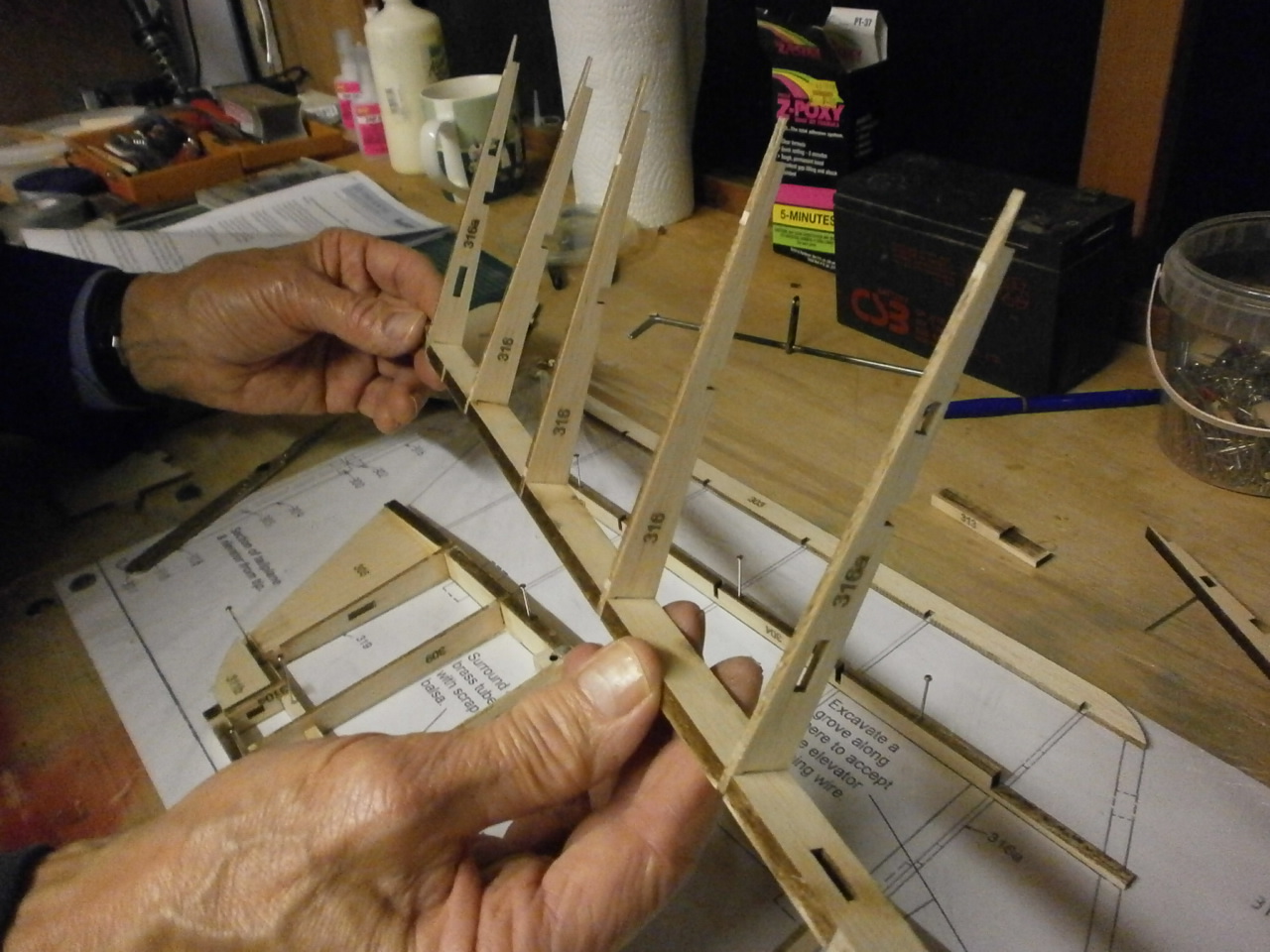
Next the leading edge piece has the ribs glued into place Picture 1 and then this in turn is offered into position where it interlocks with the centre spar and sits over the trailing edge. Picture 2
 |
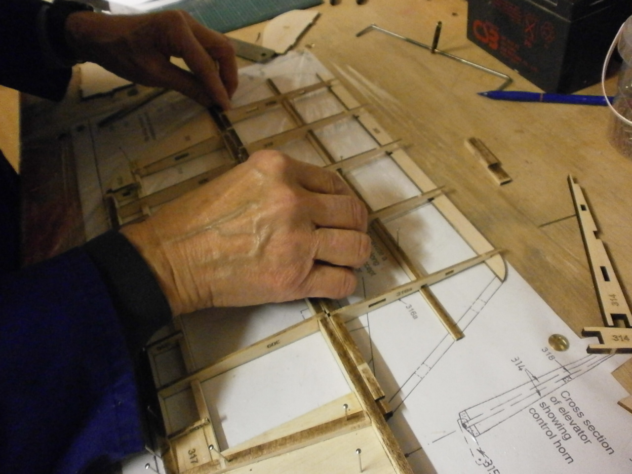 |
Once this is completed the inner and outer tips are glued into place along with the horn guide as can be seen in the following pictures.
 |
 |
The last picture now showing the completed elevator half just leaving the other half to be completed using the same methods as just described.
 |
 |