|
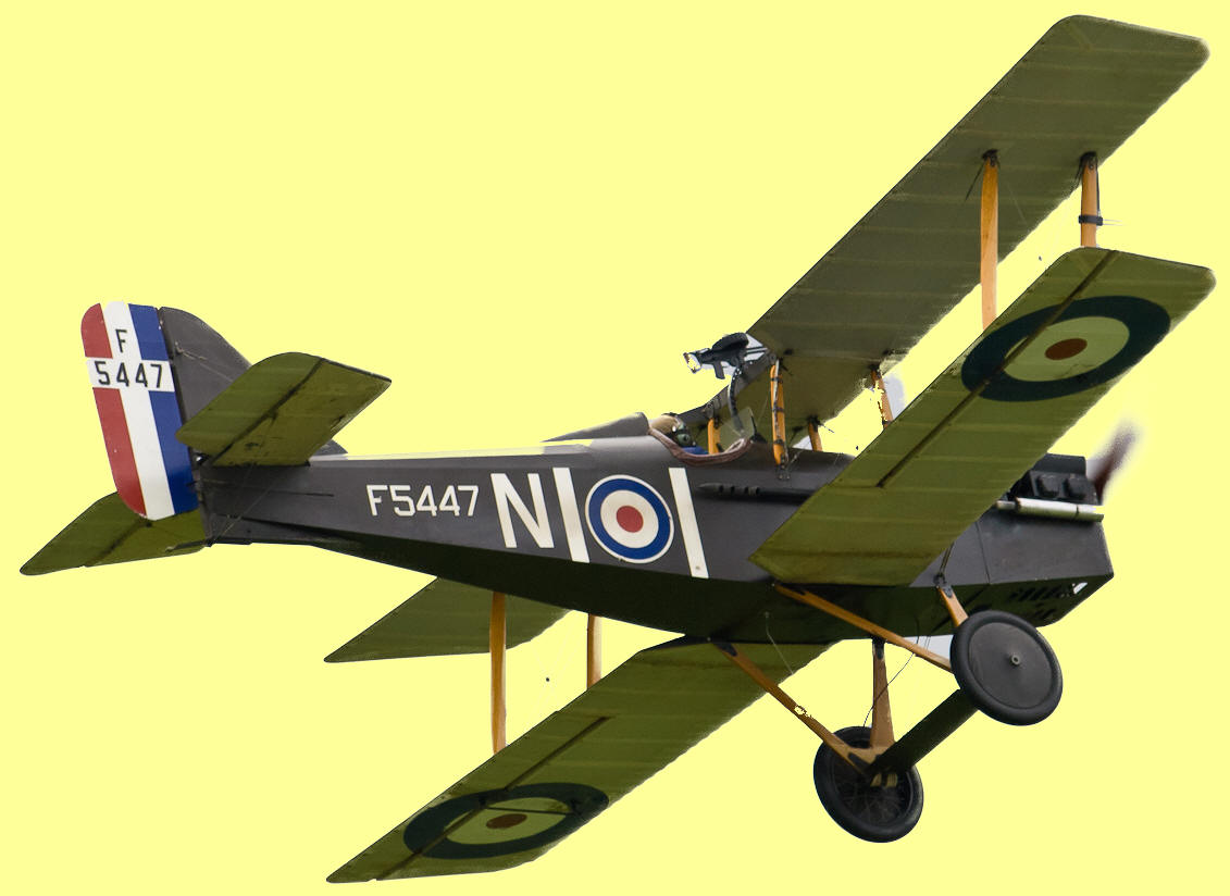
SE5A
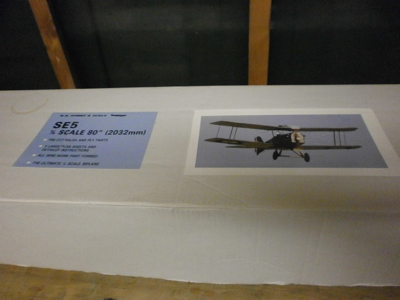
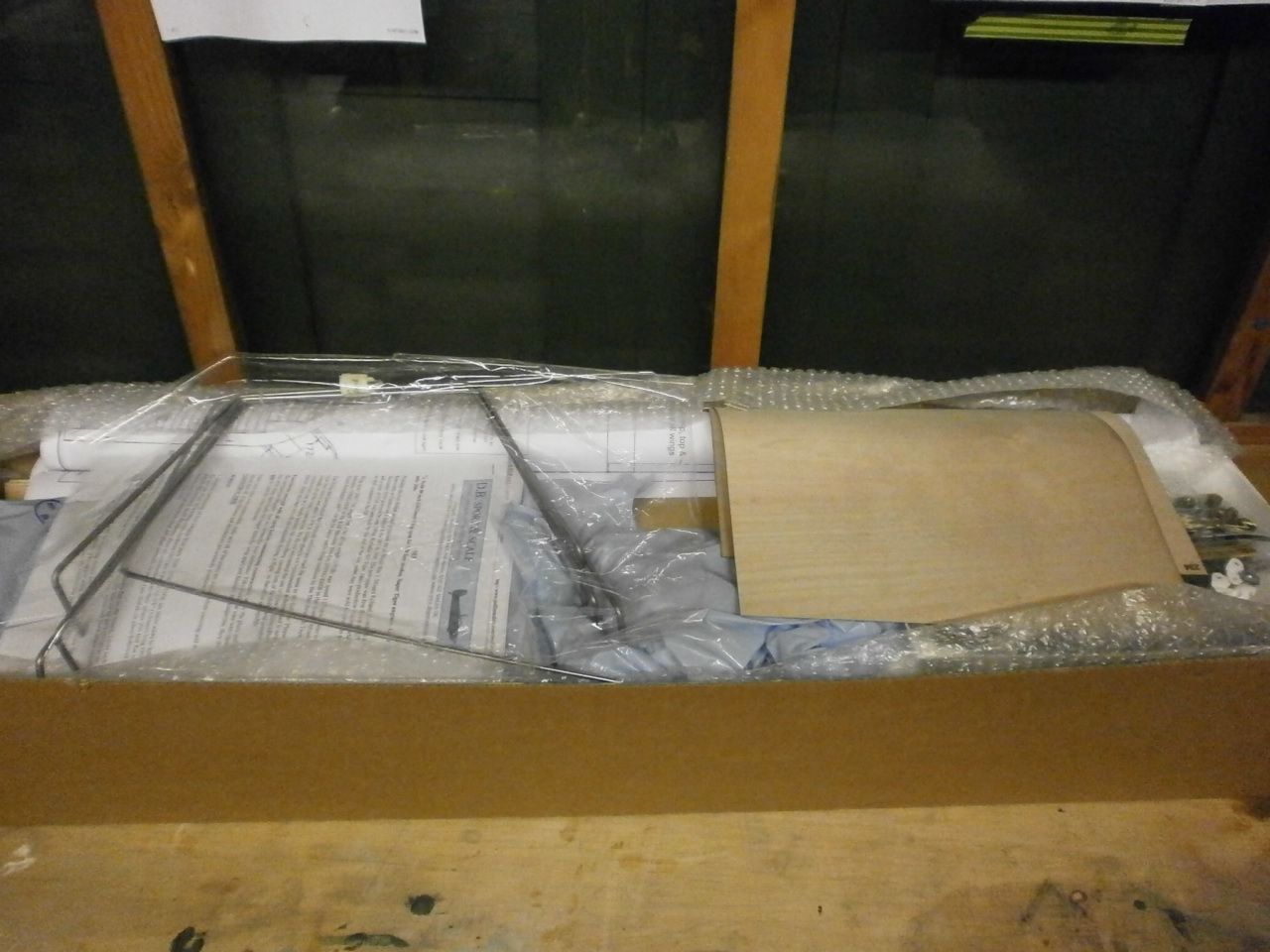
Stabiliser Elevator Build I have started project although the Sopwith Pup is still needing completion. I would not normally consider starting another project until completion of a current one. I have made an exception to the rule this time, as I will not be building this alone. I have invited a close friend with many years modelling experience to corroboratively help put this kit together. This will enable me to carry on with the completion of the pup whilst at the same time allow me to build a scale model with a fellow modeller which is something that I have always wanted to do. This hobby is not just about building and flying models to me. Its also about the friendships, help and camaraderie that come with the hobby. Anyway enough of that, lets get down to business. The kit is a 1/4 scale SE5A by DB Models The first pictures below show the box
and its contents. The fixings are all high quality and you can see the care that has gone into the selection of all the parts that will make up this model it is a credit to the manufacturer.
Taking into account the complexity of the
build, we both decided that to start with, it would be a good idea to tackle something very straight forward to build. Looking
at the plans and instructions a joint decision was made to start with the
top wing centre section as this looked like it would be fairly easy to start
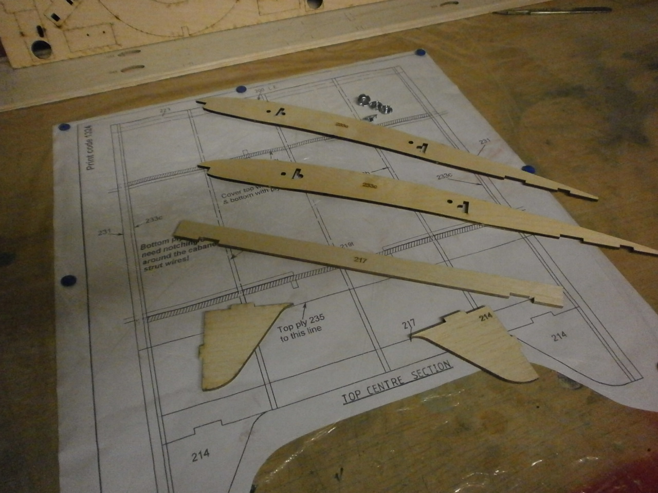
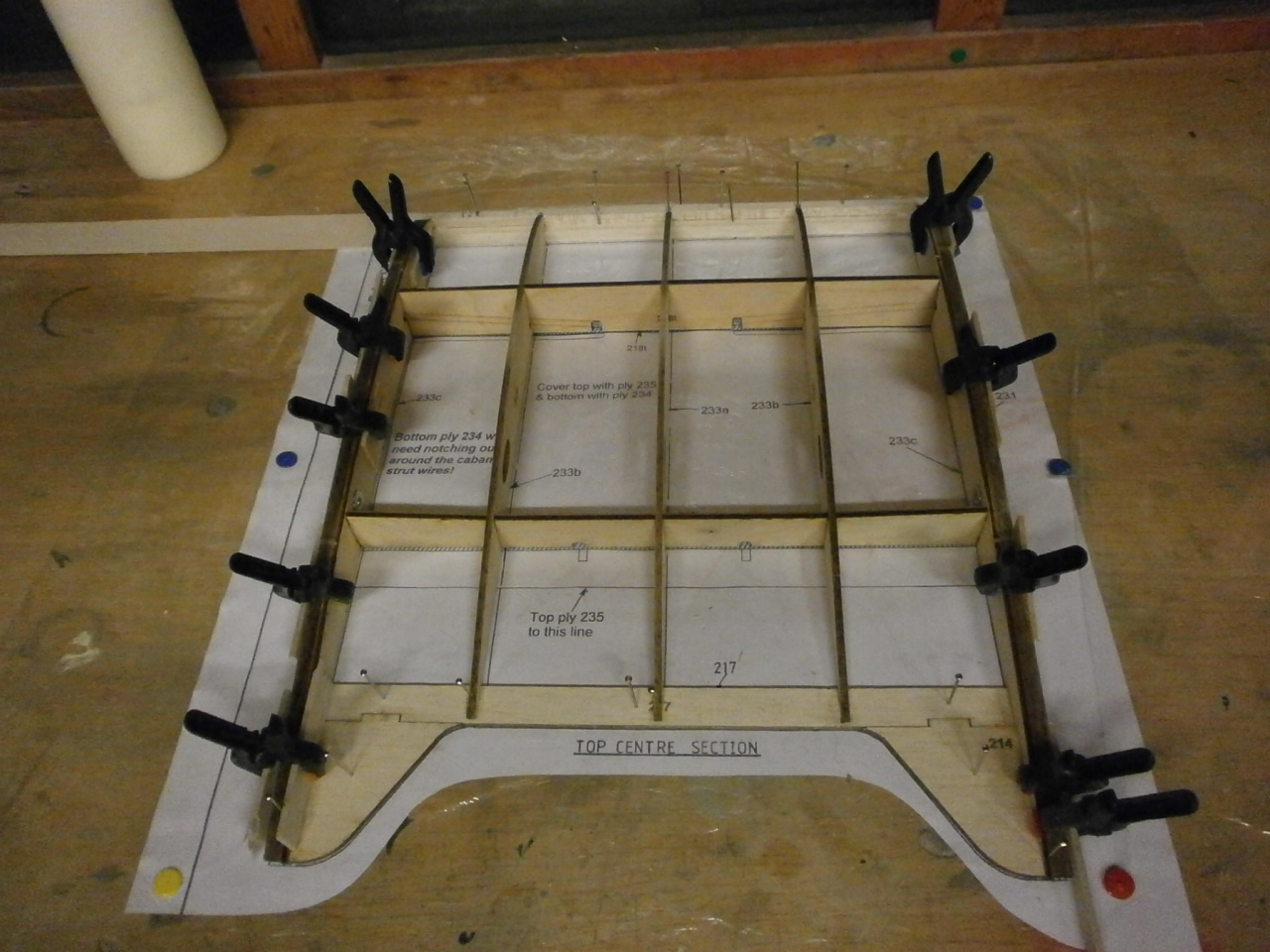
with. Below are pictures of the plan and some
of the parts required, with the next picture showing the completed structure made up over the plans.
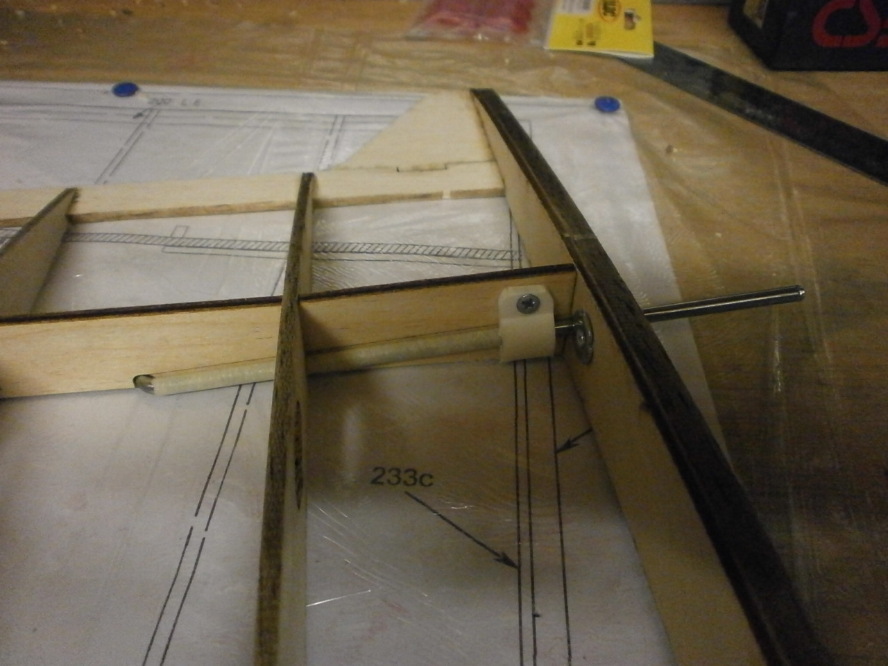
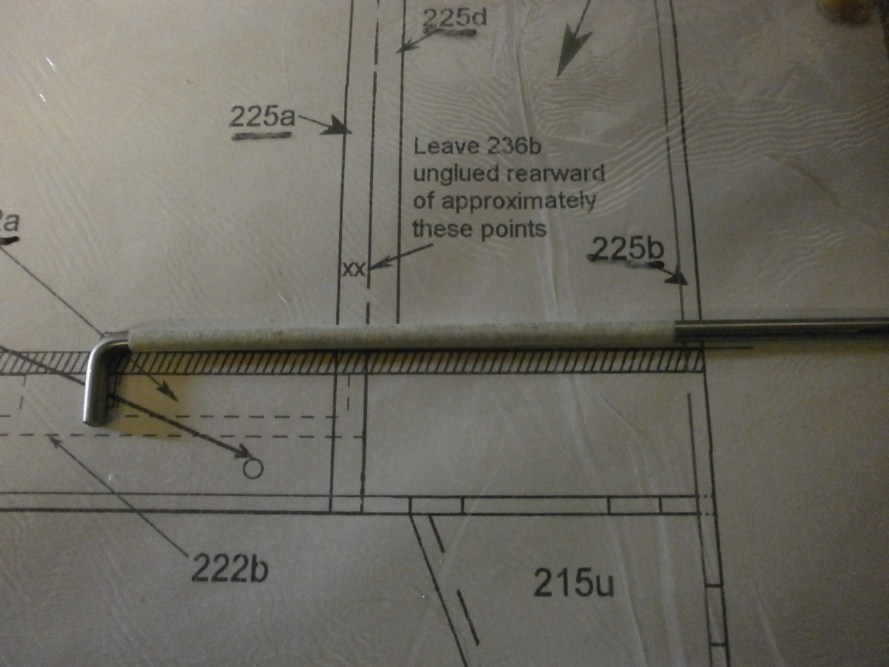
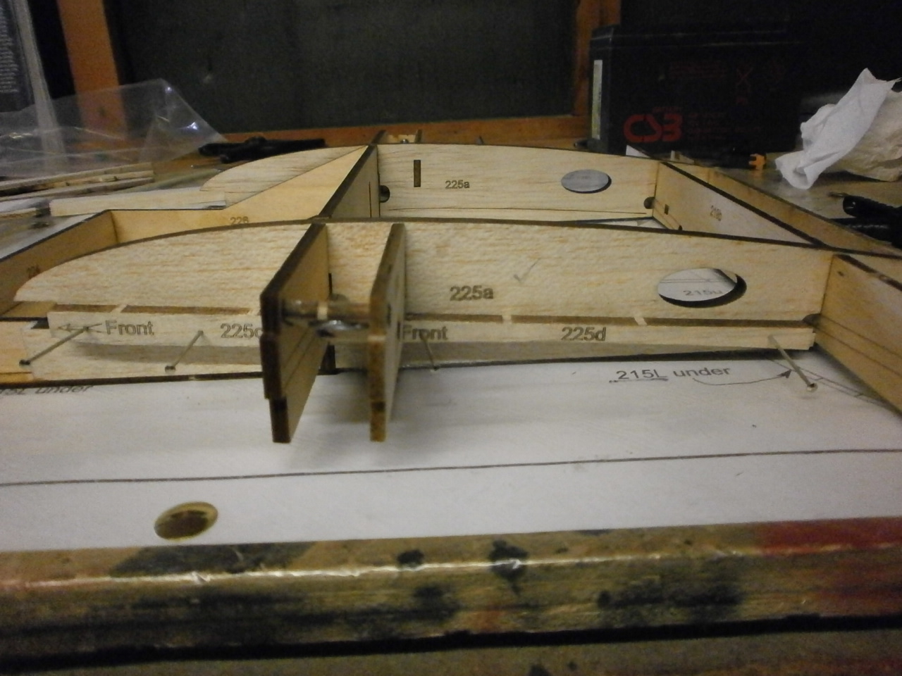
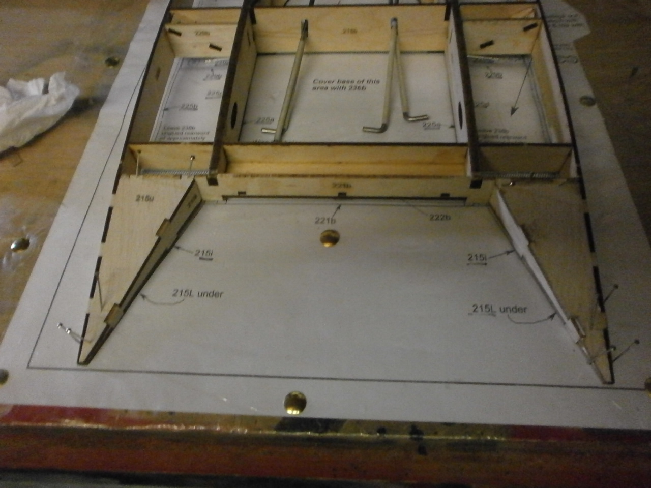
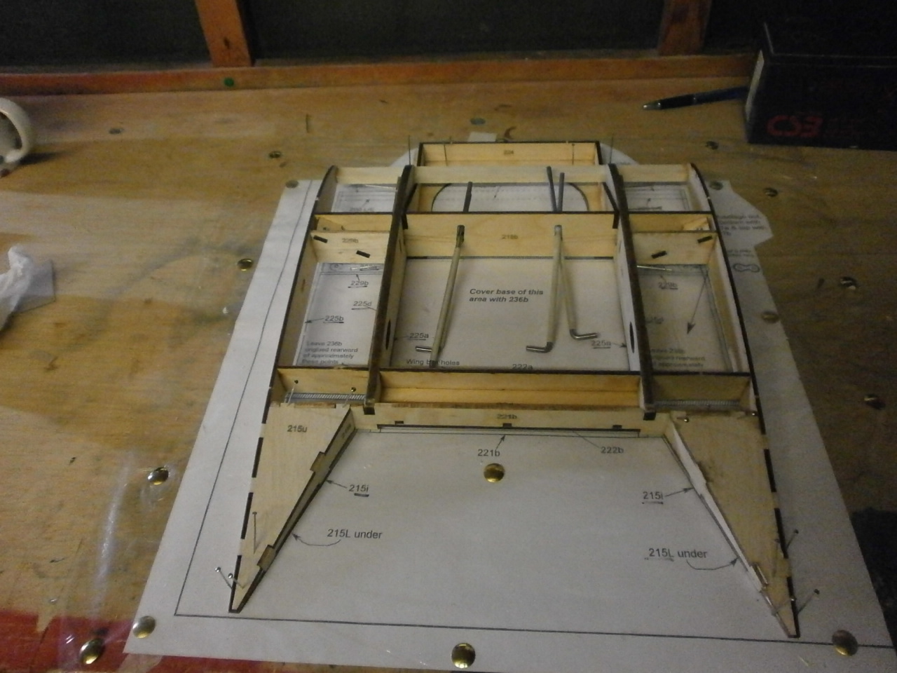
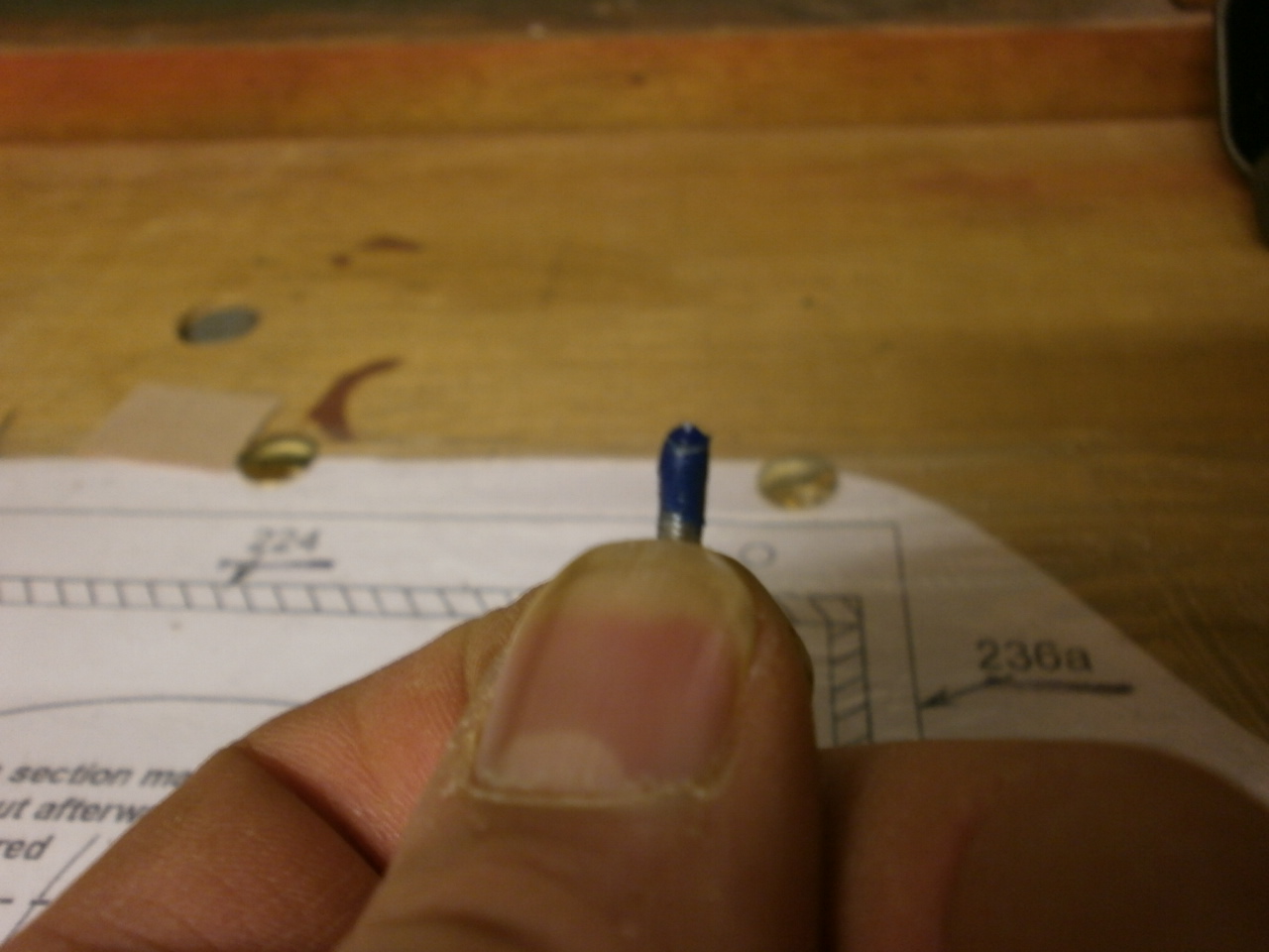
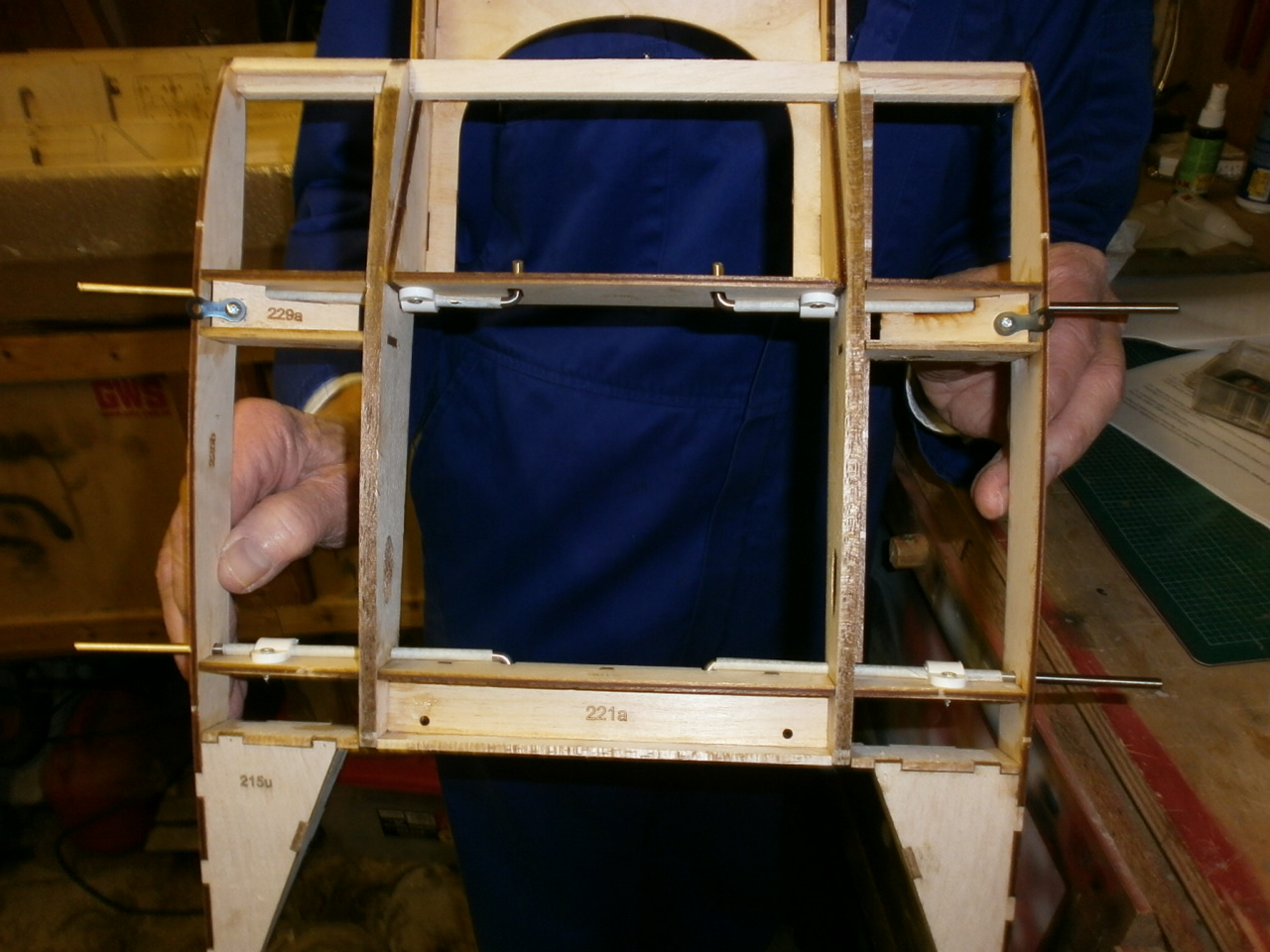
Once the centre section ribs and spars had all cured and the end of another week, a call was made to my building partner and a date setup to carry on with completing the centre section. The next job in the instruction manual is to install the wing locating rods. The first thing we had to do here was to wrap each rod with masking tape. See first picture below. Once wrapped the rod is worked into position through the cut out holes in the ribs with the L bend facing out towards the trailing edge for the rear spar and out towards the leading edge for the front spar. You will see from the second picture that we have added a saddle clamp to aid with holding every thing into place. (the rods are only super glued into place) This idea has been pinched from the article running in the RCME as we both agree, that although once glued up the assembly seems to be very strong. This approach ensures a belt and braces approach, as once everything is covered it will be impossible to get to the rods carrying out major surgery.
The Following pictures are showing the Zap being applied to each of the rods that sit neatly against the spars.
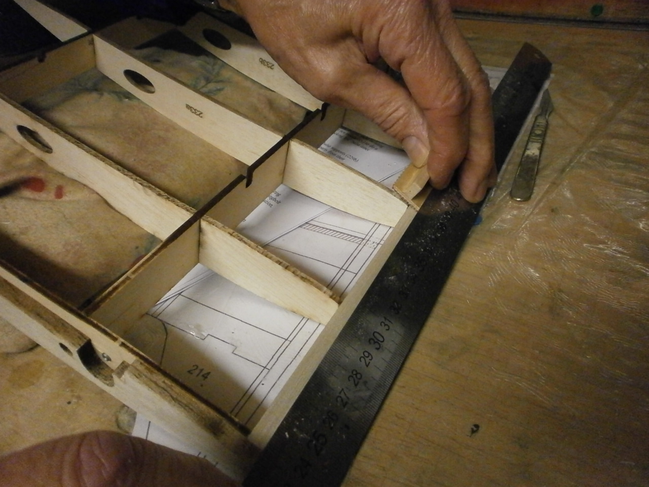
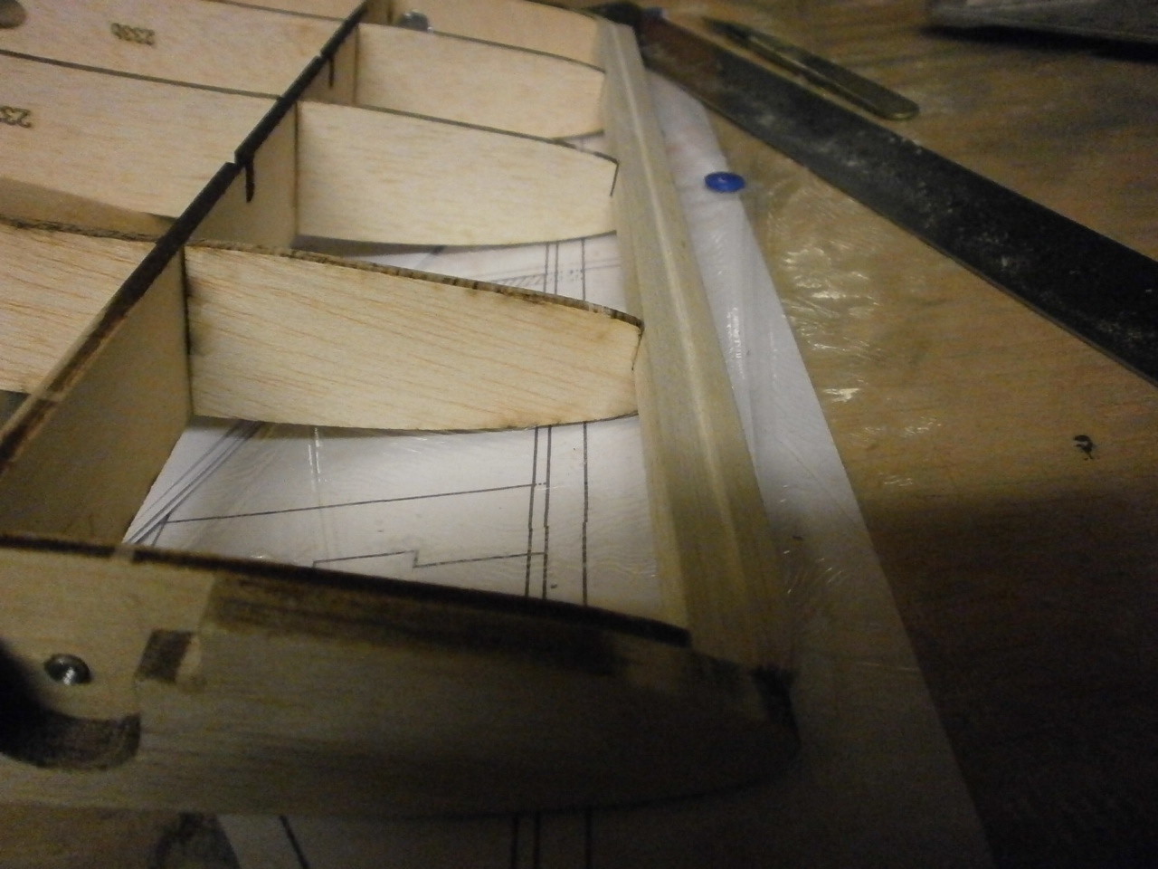
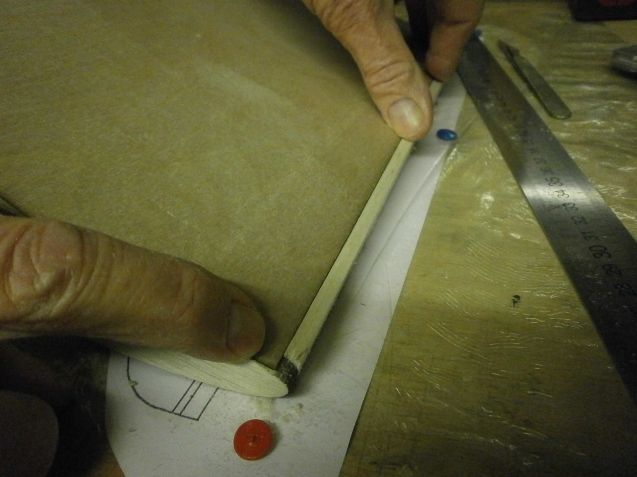
With the above now completed, we turned our attention to the next item on the instruction sheet, the bottom sheeting. This caused a little confusion, as the instructions do not say whether the 1/64 ply sheet should sit on top of the leading edge or be flush. Looking at the plans also gives no indication, so a joint decision was taken that the ply should sit flush. (not the easier of the two options regrettably) To enable us to get a flush fit it necessitated making up a little sanding block, that with the aid of a steel rule enabled us to sand a recess for the 1/64 ply whilst also being conscious that we needed to maintain the rib profile. Please do not try this alone as the shape of the centre section is awkward to keep in one position and you will also need help keeping the ruler in position whilst you sand in the recess. The following two pictures show the sanding operation and the final result.
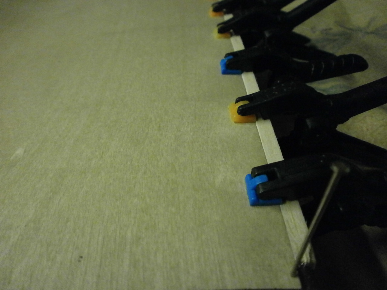
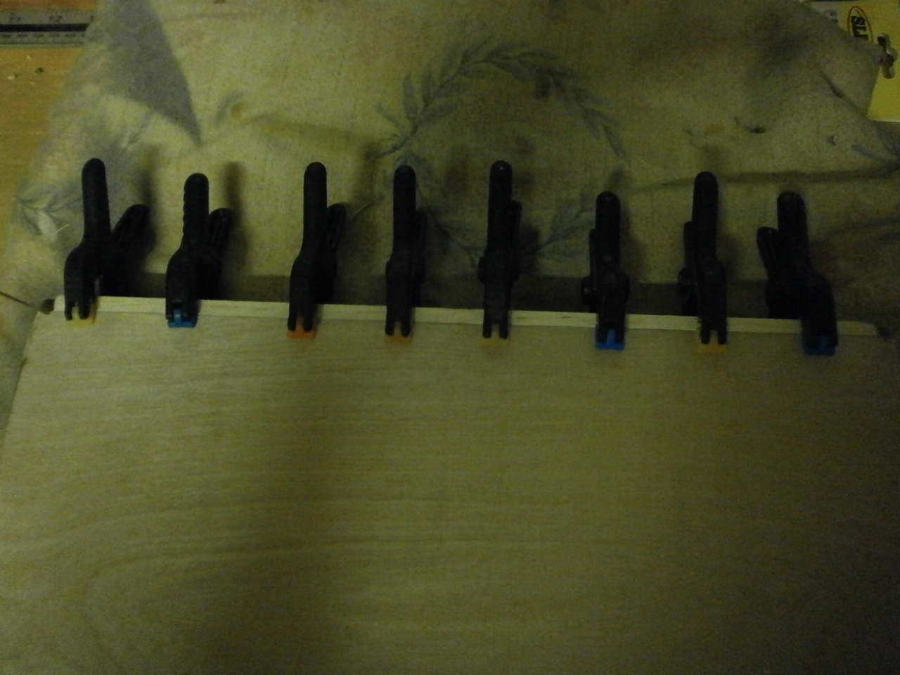
The ply is then test fitted into location making sure everything is square. Once happy with the fit the Ply is epoxied into the recess and clamped into position and left to cure before attempting the rest of the sheeting. See following three pics.
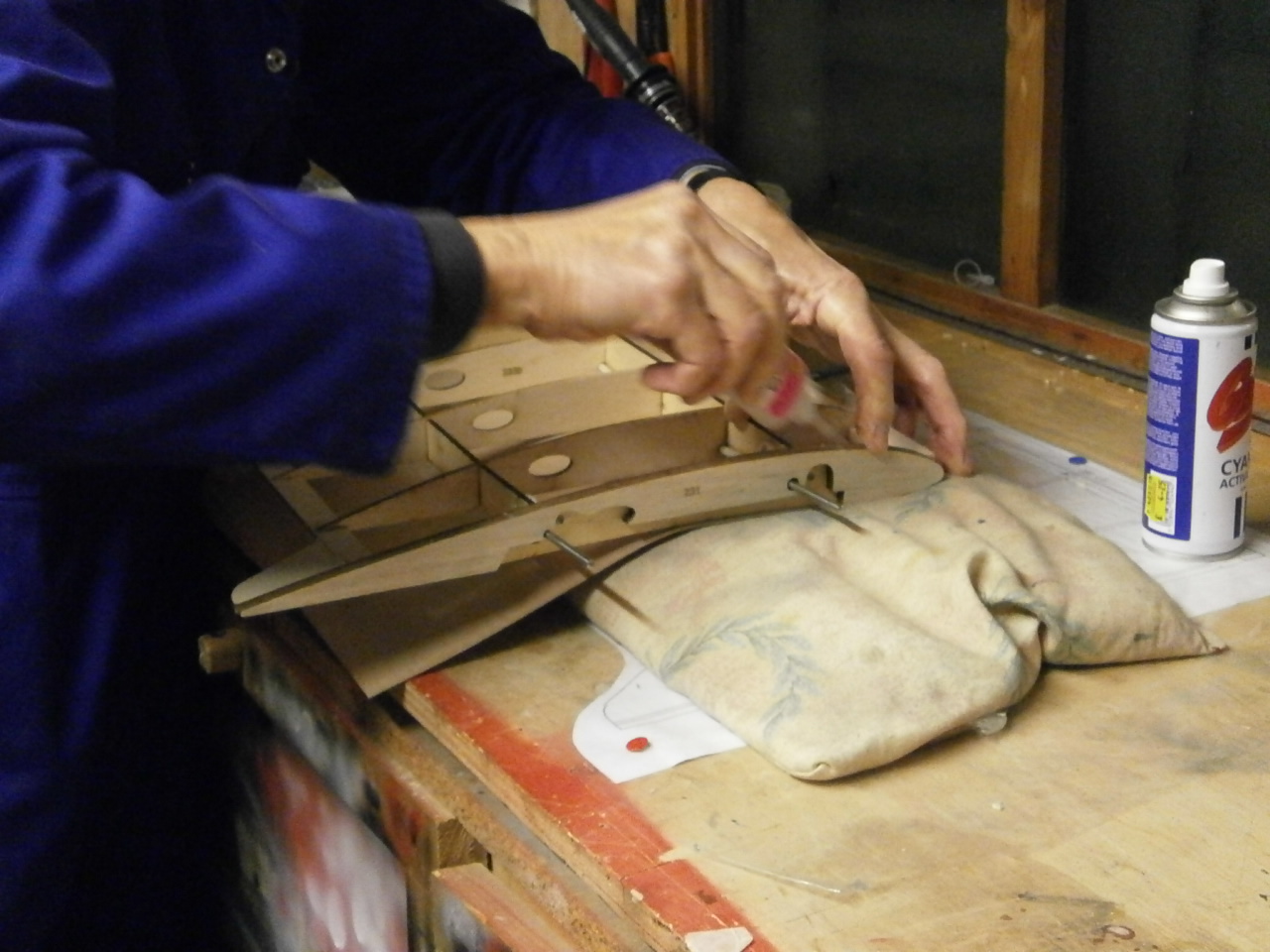
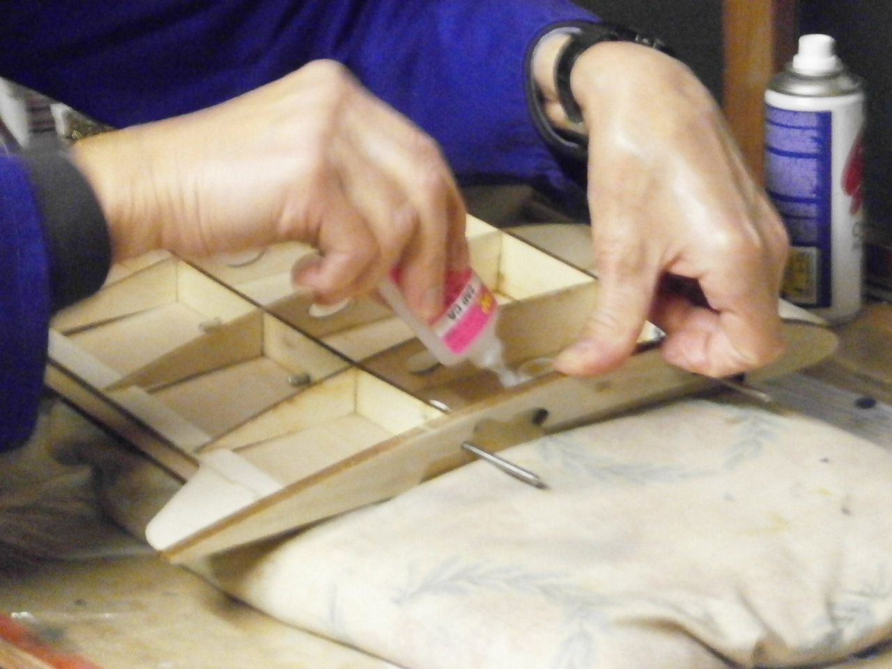
With the epoxy now cured, the clamps are removed and the section turned over. The second picture below shows the remainder of the ply being Zapped into place. Note the rice bag underneath. This has been used as it forms the shape of the rib, allowing the rib to be pushed quite firmly as the zap is applied ensuring that there is total contact between the rib and the ply.
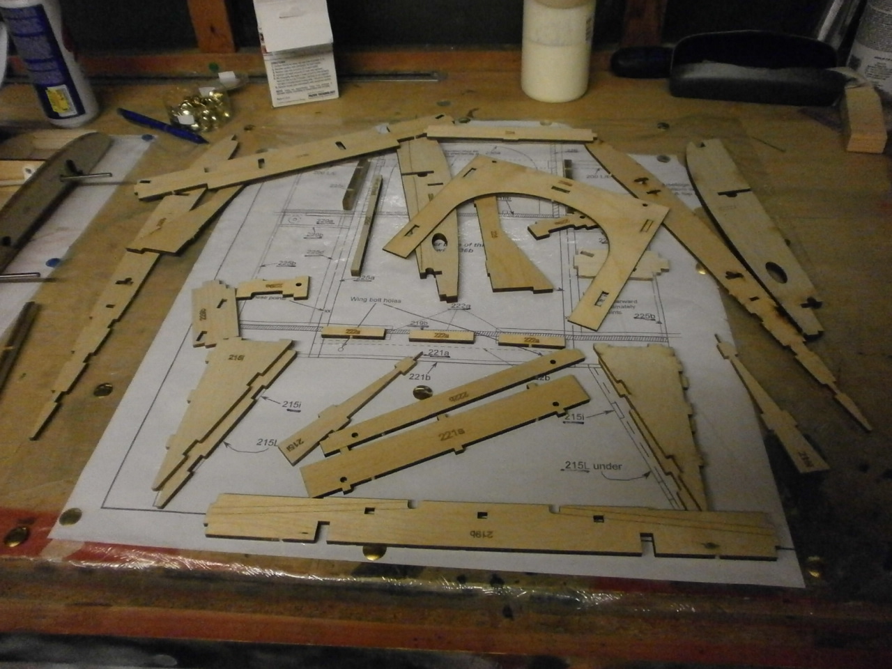
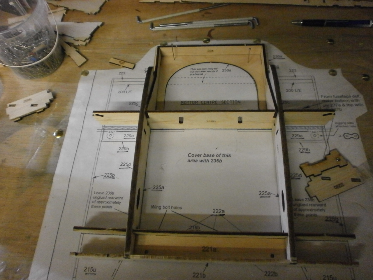
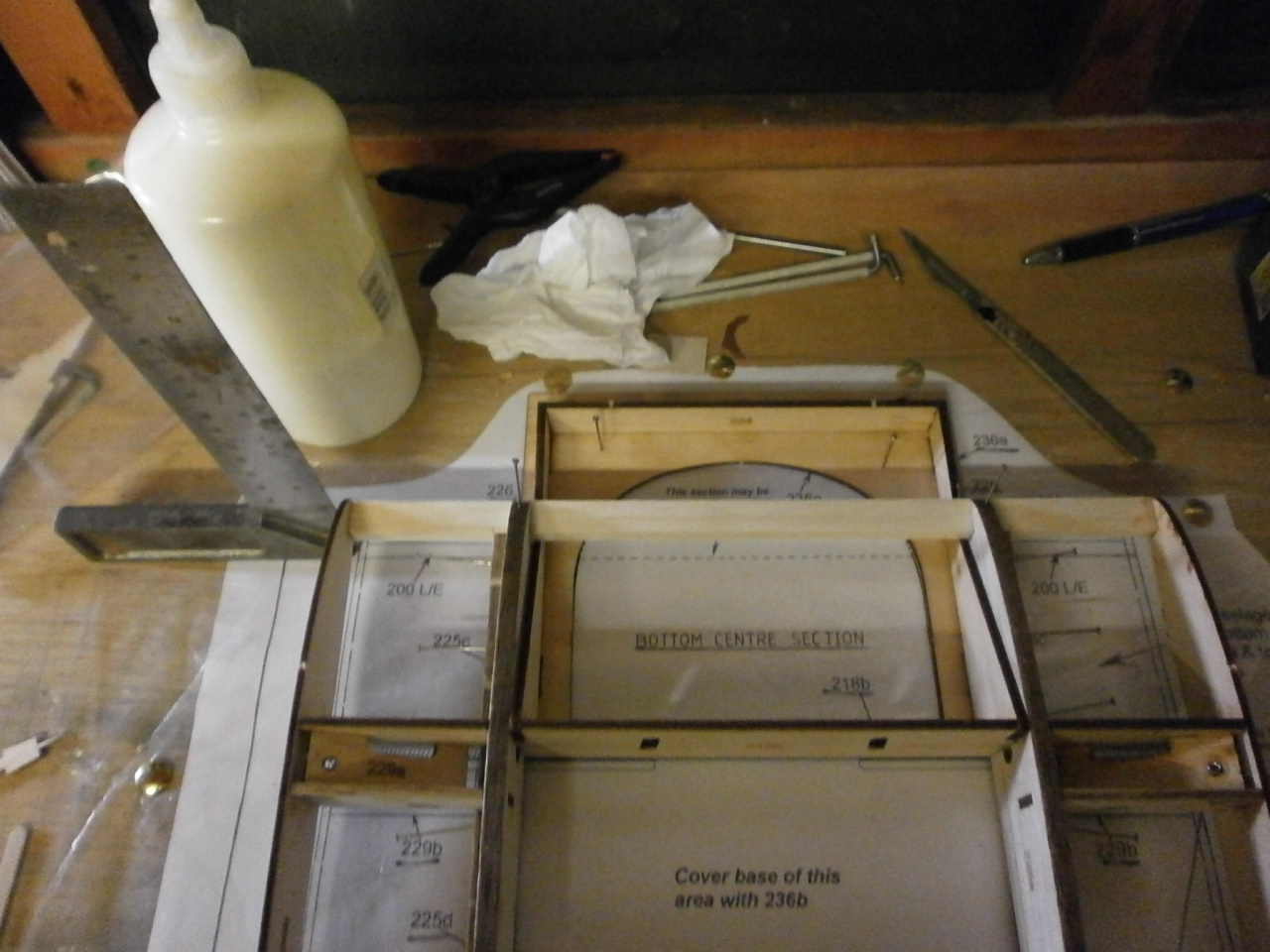
This operation is carried out starting at the front middle rib and then working out to either side and then moving to the centre and then the rear of the centre section again working from the middle rib out to either side. See first picture below. Once this job was completed, it is advised in the instruction manual that the top section is covered in the latter stages of the planes build as there may be a necessity to gain access to the structure. The second picture below shows the many parts that are required to make up the bottom centre section. We where amazed to how long it took us to source and cut all the parts from the box. (a good hour believe it or not) With all the parts located they where bagged up and time was called for this session.
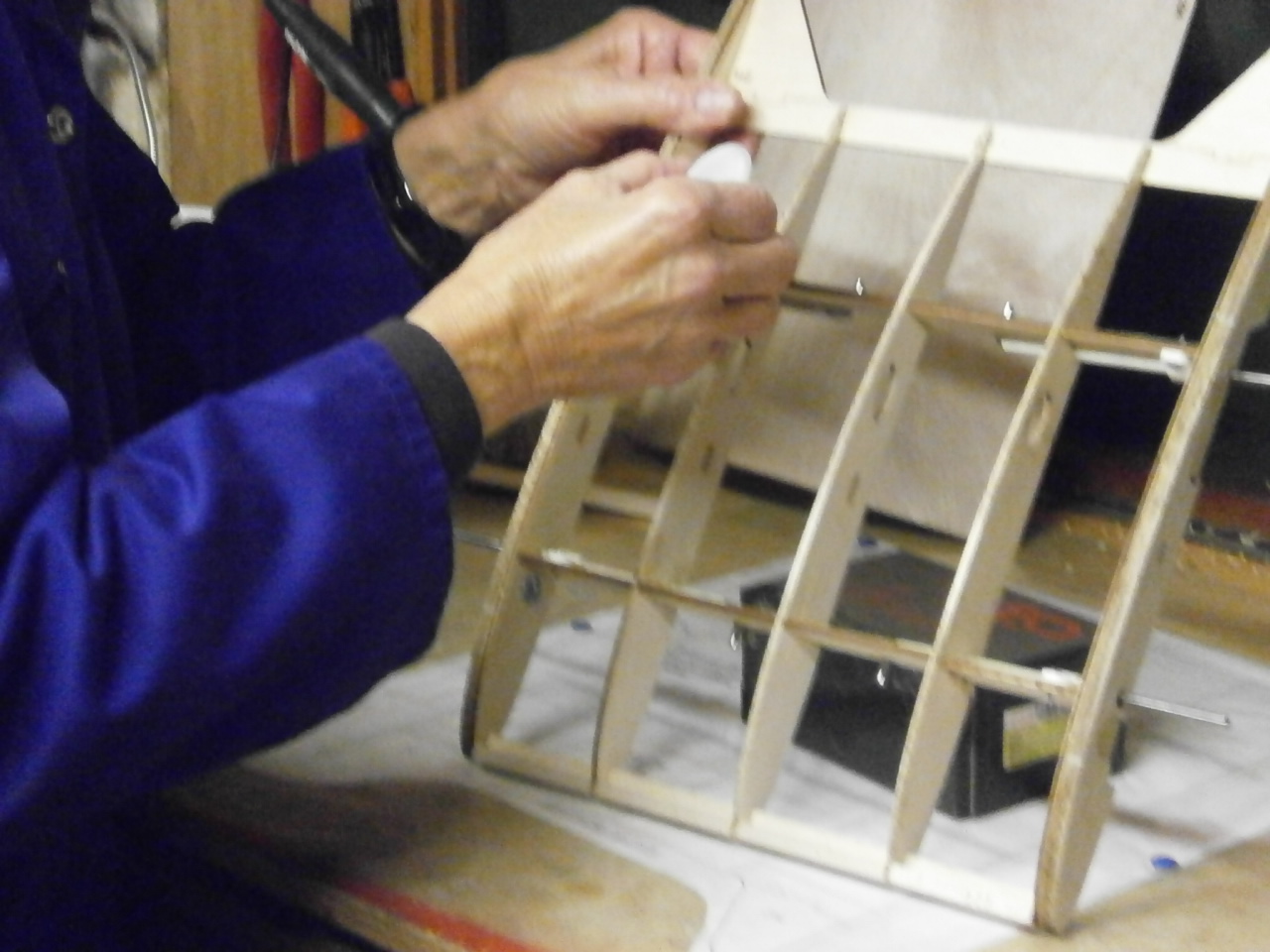
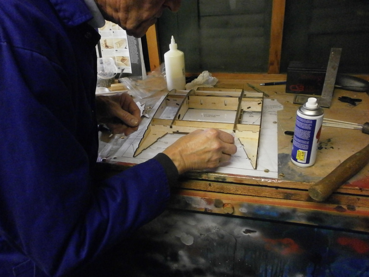
Phone calls made and times set another Friday session starts. First thing was to locate
the bag of bits and empty it out on the building board. After familiarising
ourselves again as to their locations on the plan, the fun then begins. This kit is like a giant 3D jigsaw.
All the parts
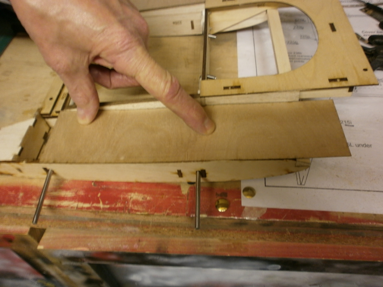
have to be located and test fitted into place. The to main ribs for instance have a guide mark on them to locate the ribblet section profile that is used to locate the ply covering later on in the construction process. See pictures below with first picture showing guide line traced onto a piece of low tack frisk film that is then removed and transferred onto the opposite side of the other rib (pic 2) now giving us a handed pair of ribs with the guides both now on the outer side of the structure when placed in their final position.
Again another two pieces that need to be handed are shown in the first picture below
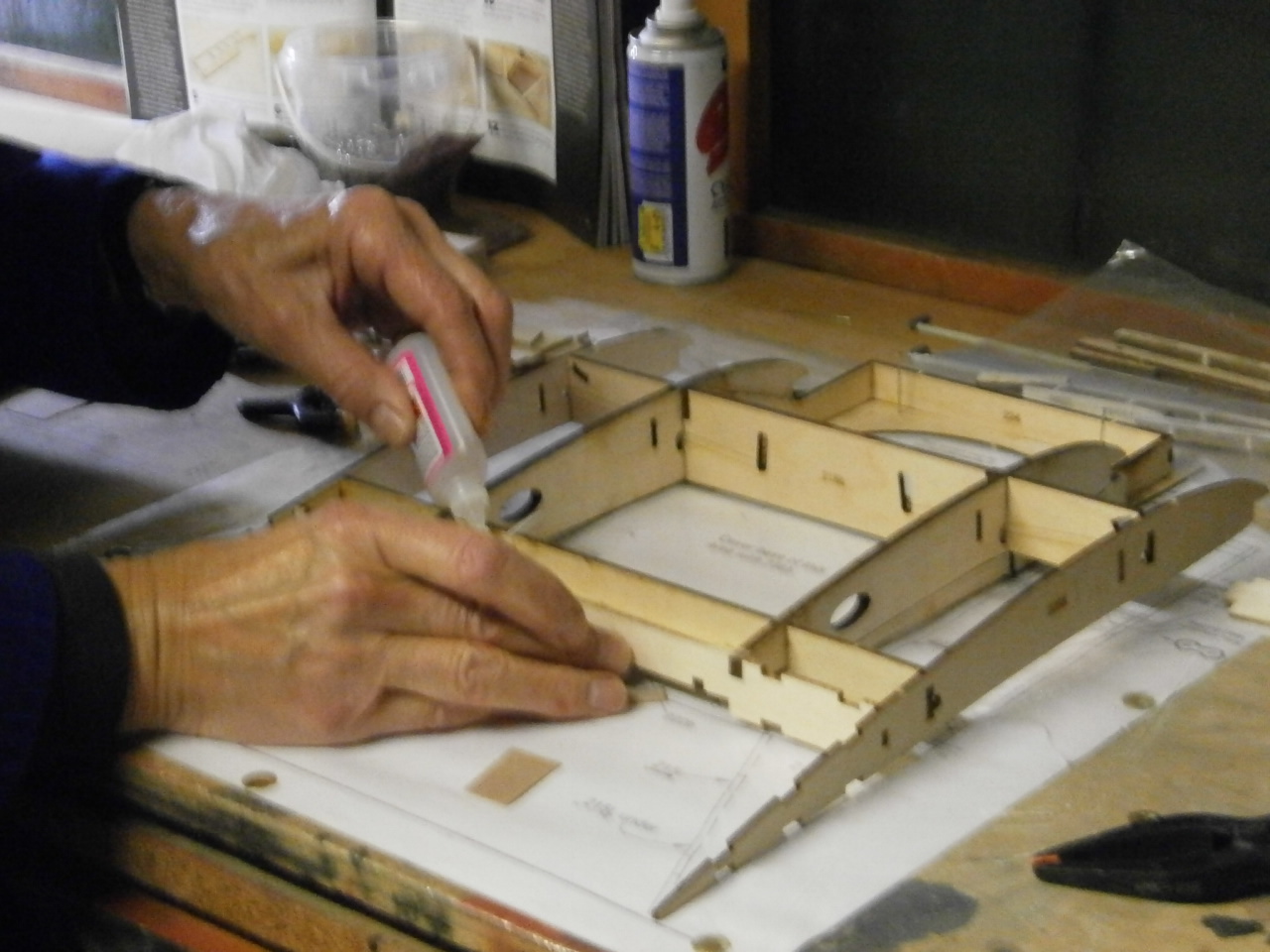
As mentioned above all the parts have been dry fitted to ensure everything lines up and ends up in its correct location. Now confident
that we understood where everything needs to go, we started gluing everything
together, or should I say my building partner. A joint decision was made to carry out sections at a time although you could piece everything together and zap it up all in one hit. Doing it in sections enables you to ensure that everything remains square before moving onto the next section. We where both surprised at how well the parts interlock and once the structure was completed how strong it becomes
Further pictures below showing the construction of the remaining pieces to finish the skeleton
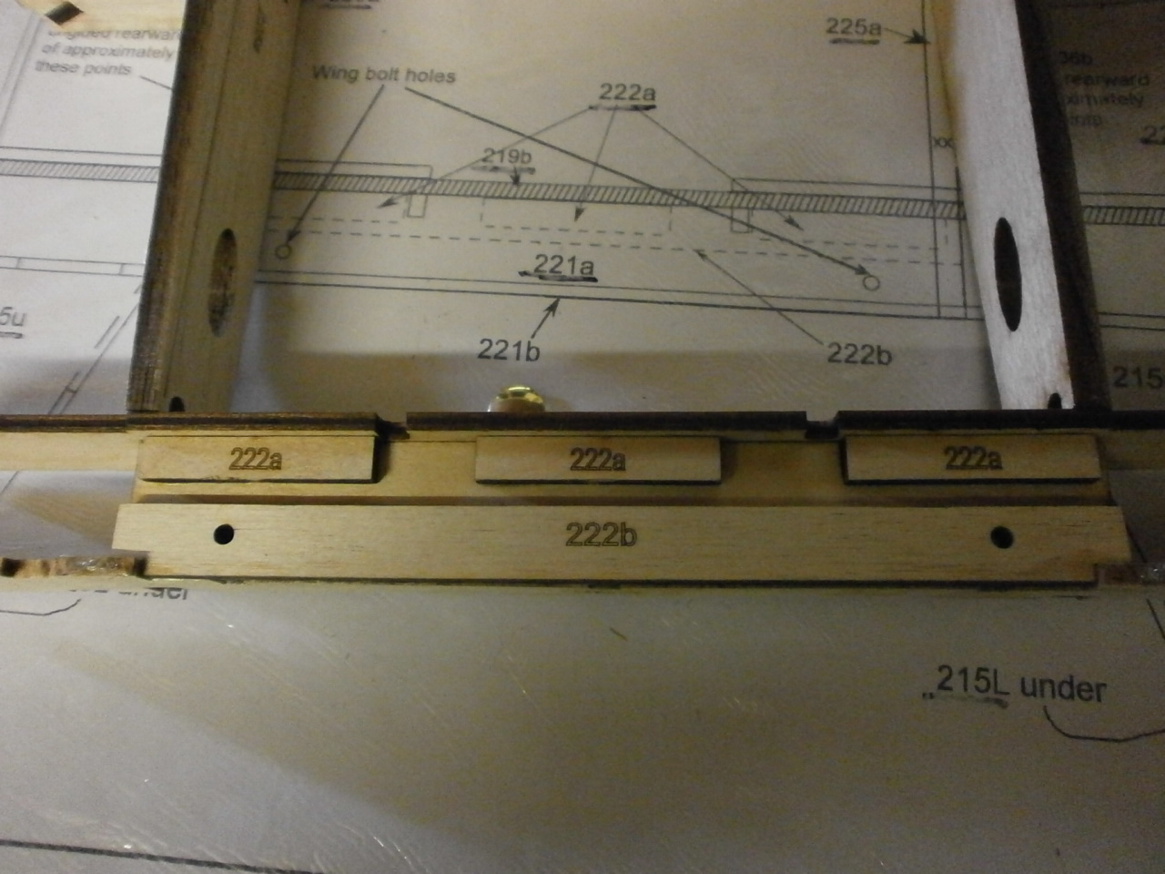
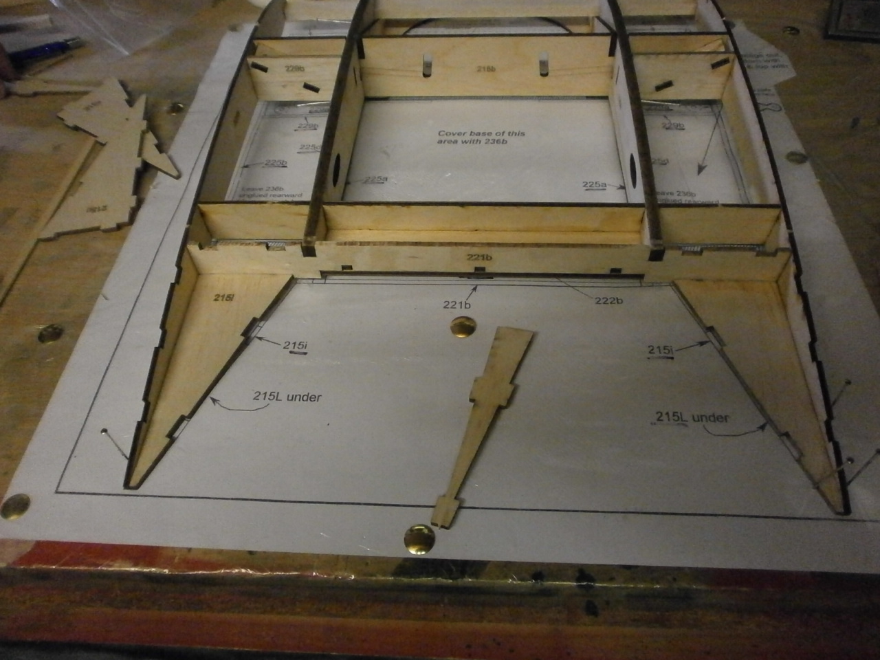
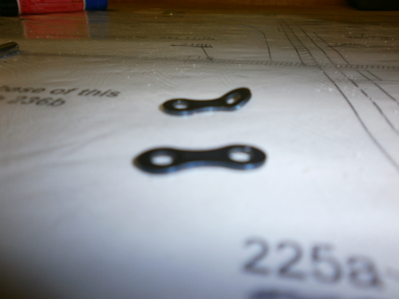
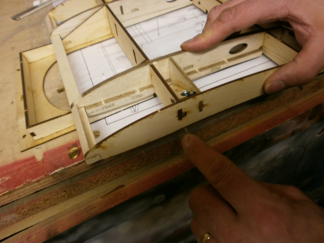
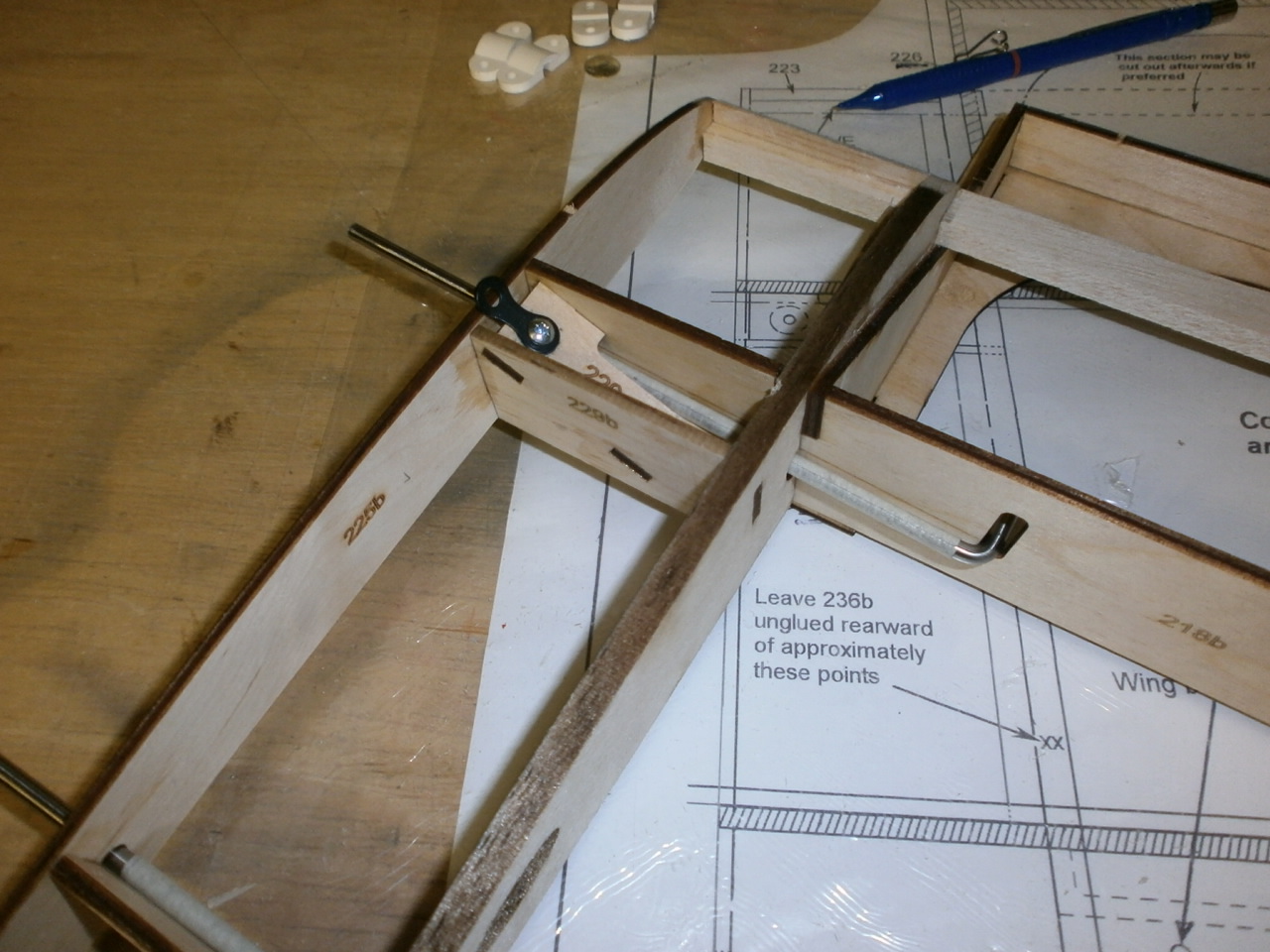
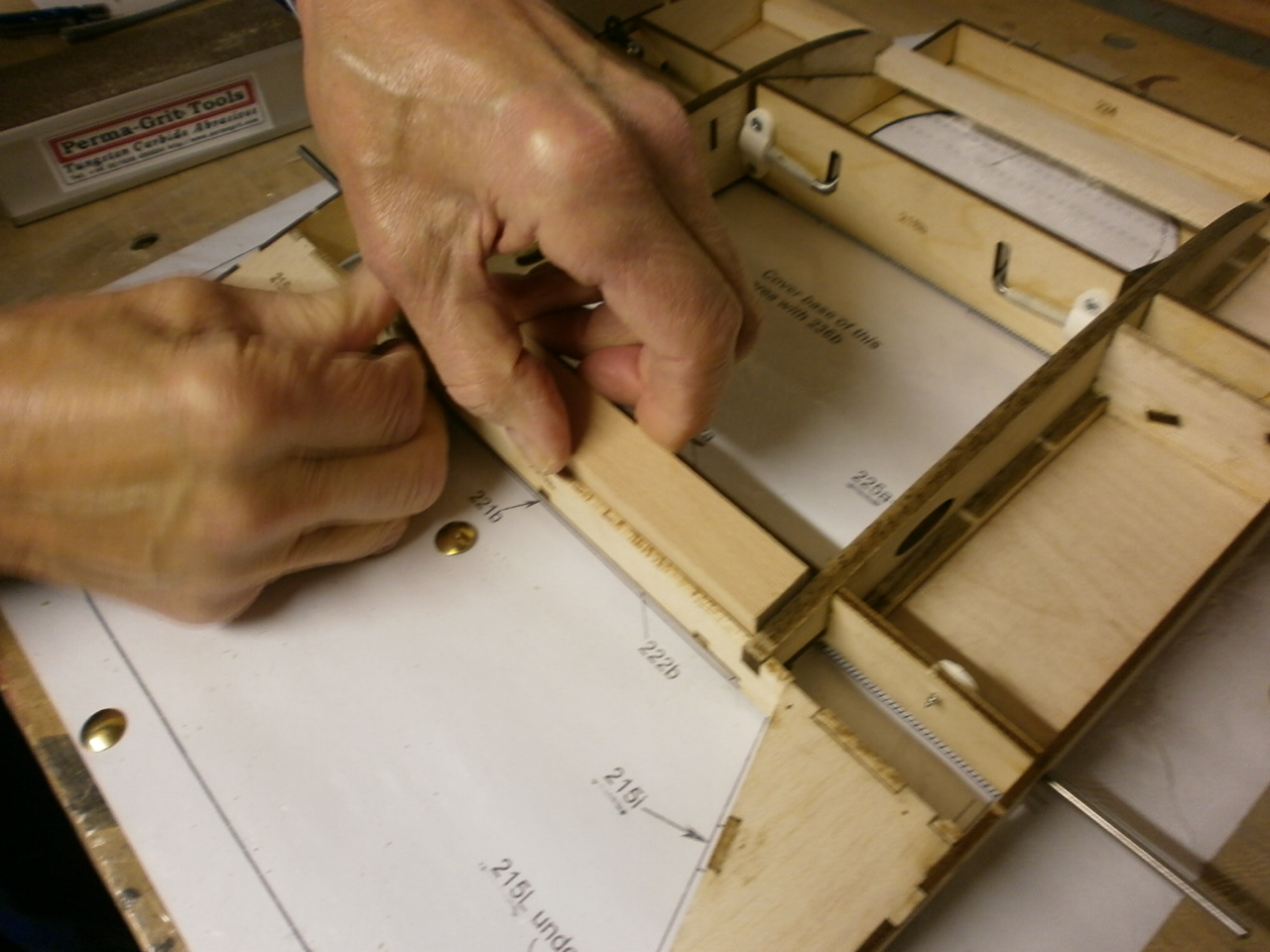
With the main skeleton now complete there are just a few small hardware installations left to do. The first of these is to install the rigging wire retainers. In the first picture below you can see that these need to be bent so that when they are placed into position, they stand proud of the outer ribs. In the instructions it says flex a bend. In reality you need to place the retainer in a vice and hit it with a hammer. Once bent they can be placed into position and secured with the retaining bolts supplied. You will see in the second picture below that we have applied thread lock to the bolt thread, as this bolt will be hidden behind the ply skin to be placed later on in the building process and again major surgery we be required to get to it if it ever became loose.
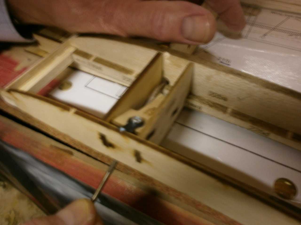
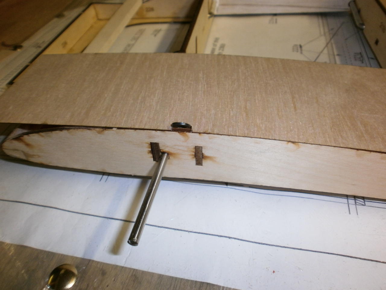
The next picture showing retainer now screwed into place . With that done we then set about installing the wing guide wires. The second and third pictures below show me filing out an angle in the hole that these wires pass through, as when first offered into position would not fit. Only a small amount of filing was needed to ensure a perfect fit.
One refitted the wires are glued into position using the same process as described on the top centre section.
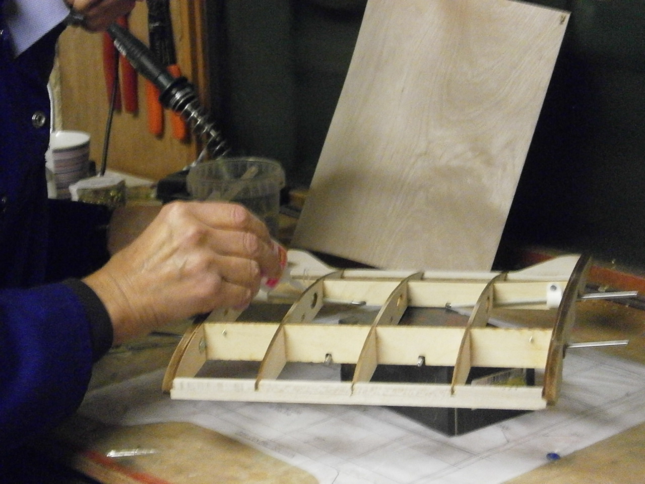
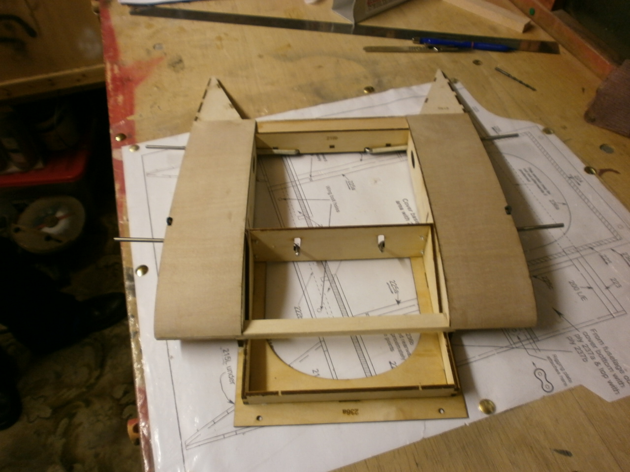
Everything in place now ready for the ply skinning to be added. First we fitted and glued the bottom ply sheeting which is pre-cut to size. Second picture below.
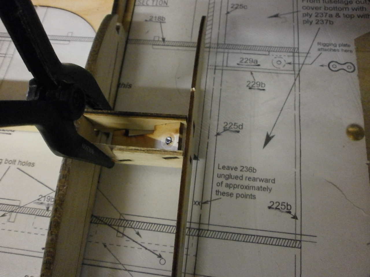
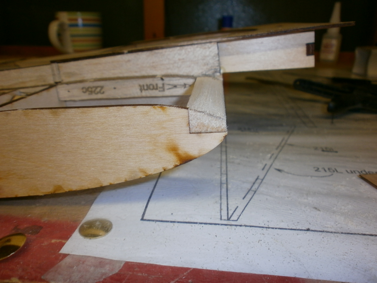
Once both underside skins where in place the section is flipped over ready for the top skins to be installed. Hold on a minute. Looking at the wing mounting bolt area, this to me looked as if it would not stand up to any hard landings as this area also accommodates the rear undercarriage wires. I'm sure that the manufacture has thought this out at the design stages and it is just my nervousness getting the better of me. But again to be belt and braces and after discussing my concerns with my partner in crime for this project, we opted to place a length of beech wood into the available space. This was cut to size and epoxied into position. Once all dry the holes are drilled out in their required locations ready to accept the wing bolts See first picture below. Right back to the top skins. Before these can be located and glued into position we needed to sand the leading edge to the rib profile. see second and third pictures.
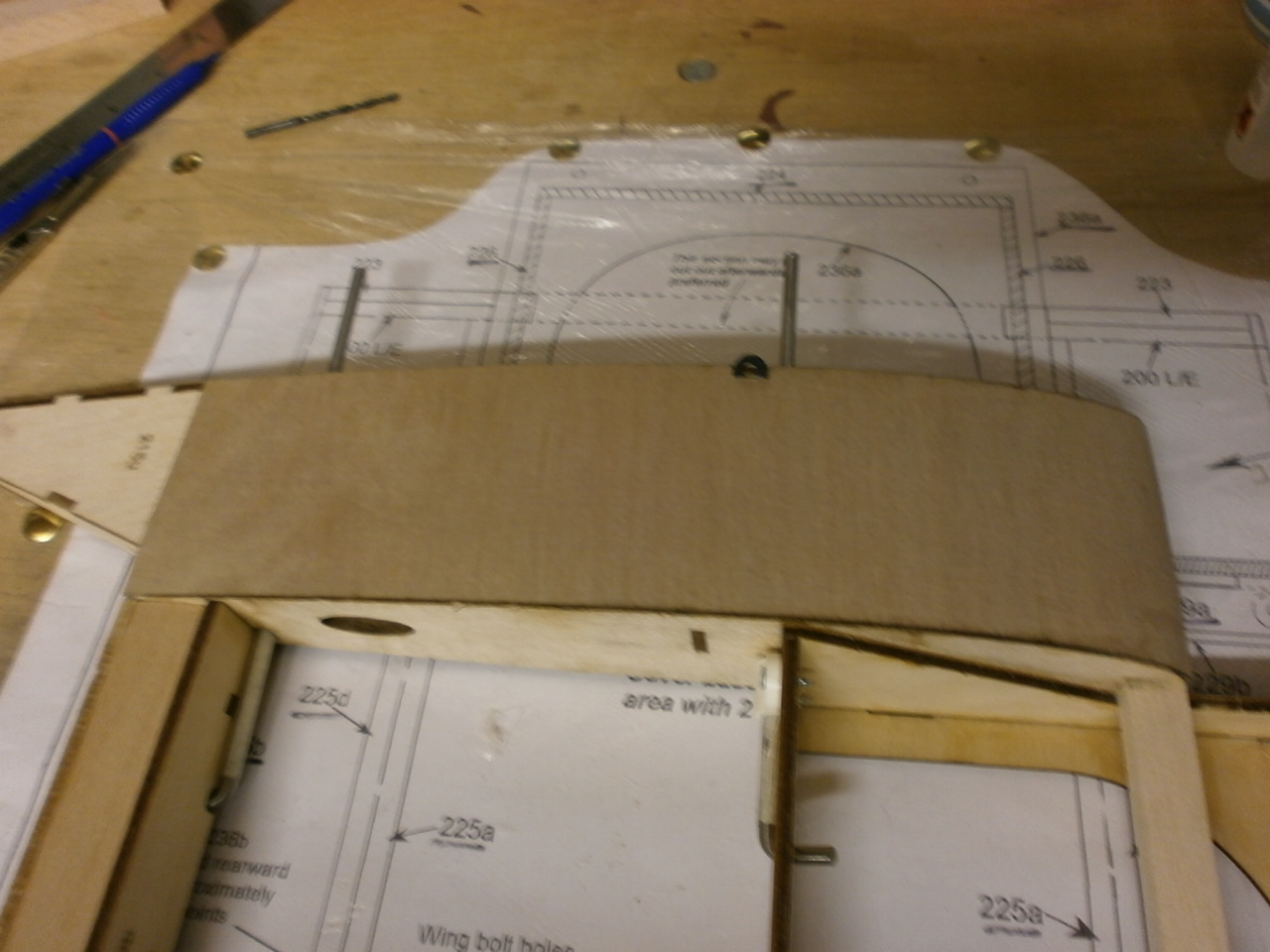
Once happy the next job is to cut out notches in the ply where the rigging retainers exit out of the top of the rib. See second Picture below.
The following two pictures show both top skins now firmly glued into place. The only thing now left to do is place on the bottom centre ply sheeting, but we are going to leave this for now as the under carriage wire sits under this so we will wait until we get to that stage later on in the build..
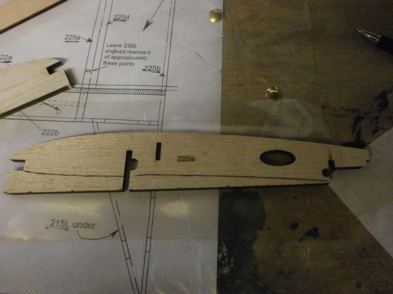
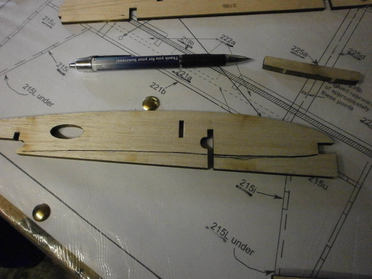
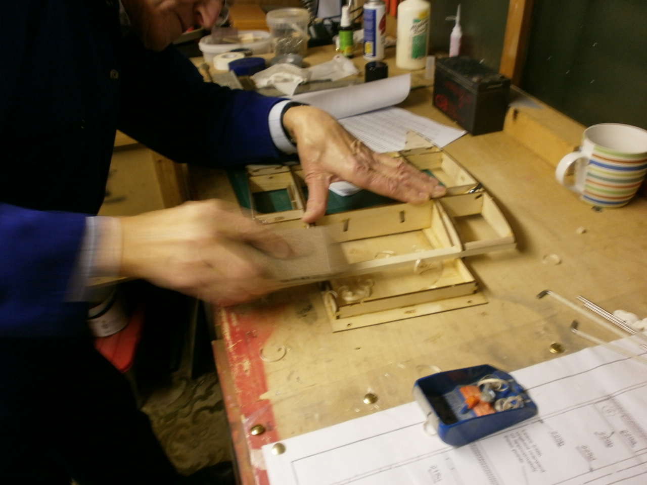
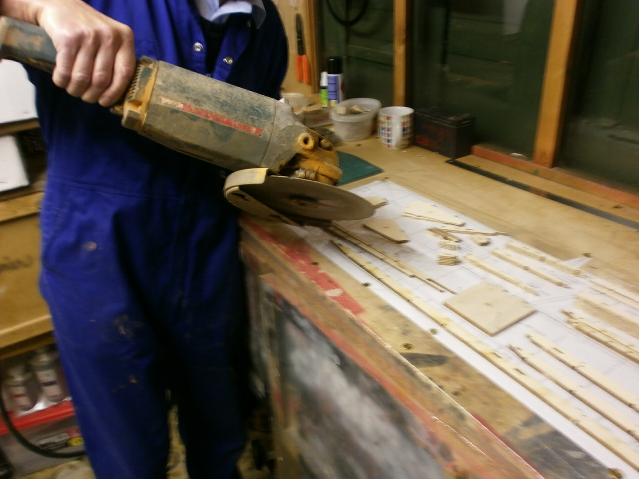
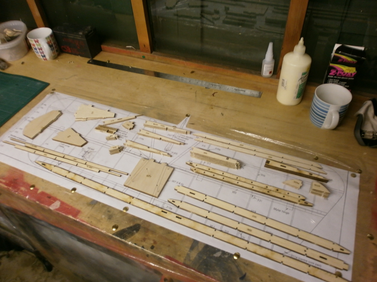
Below you can see all the parts of the stabiliser and elevator that have been carefully cut out with our industrial angle grinder. ( only kidding do you know how much they cost in electricity to run)
Stabiliser Elevator Build
|