Wing Sections
With the tail sections completed, our
attention next moved onto the wings. The wings are made up of a centre
section (already completed) and two wing panels, one left one right
and as this is a bi plane we have a top wing and a lower wing to build.
So far the instructions for the previously constructed components have been
easy and straight forward to follow.
Not the case now. It is essential that you read and re-read the instructions
along with the careful study of the plans. The wing plans are on two separate
sheets, one for the left top and lower wing and one for the opposite hand.
Each plan shows both the components that make up the top and lower panels
and as these vary considerably it is quite easy to confuse which part goes
with what panel. Even the main ribs and riblets have subtle differences, so
the greatest care is needed when building both the top and the lower wing
half's ensuring that mistakes are not made.
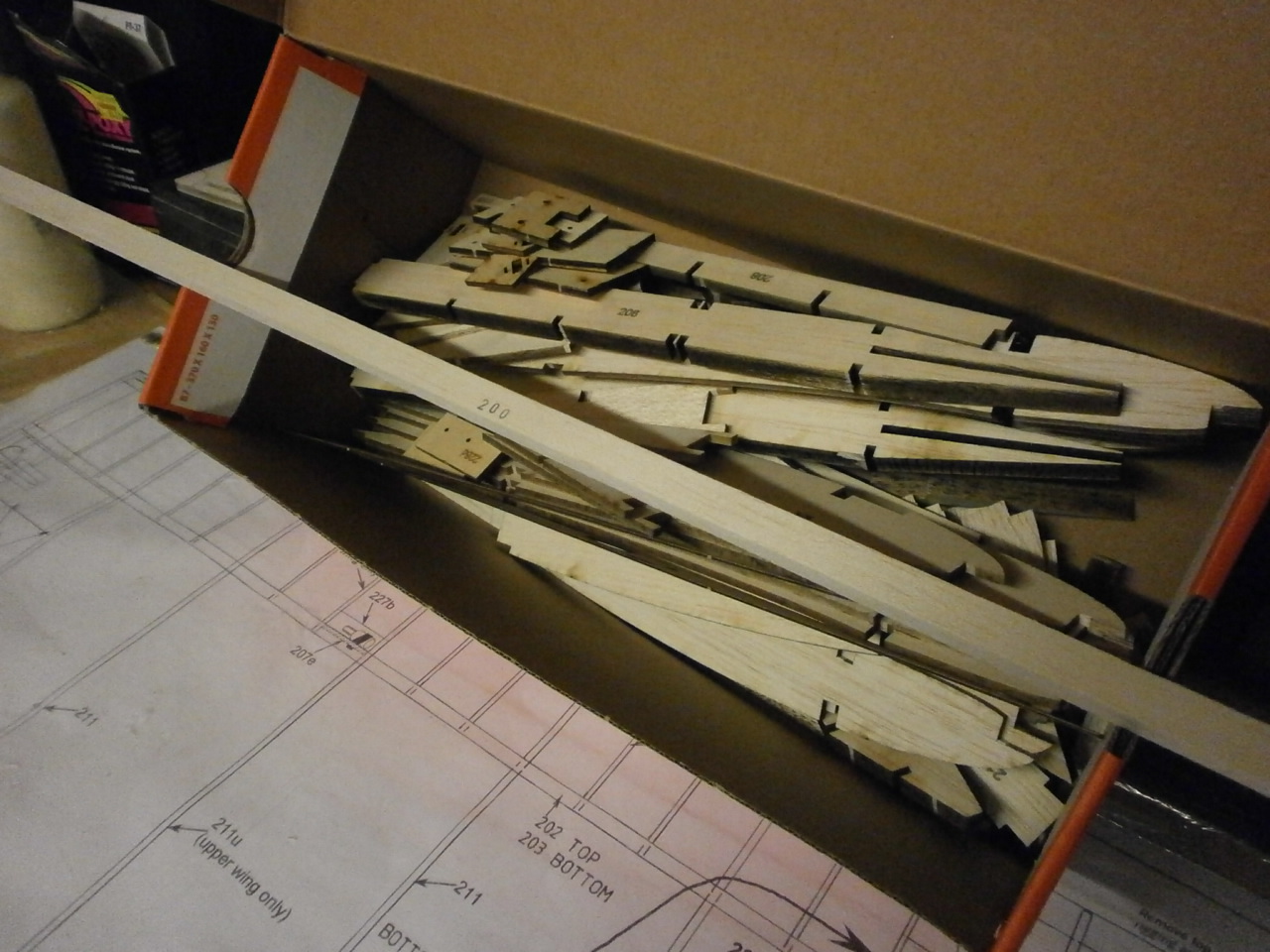
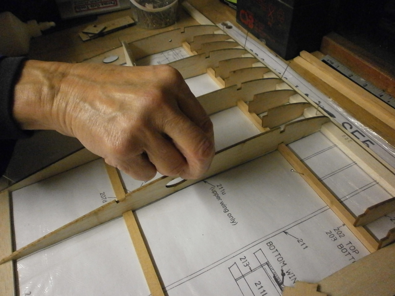
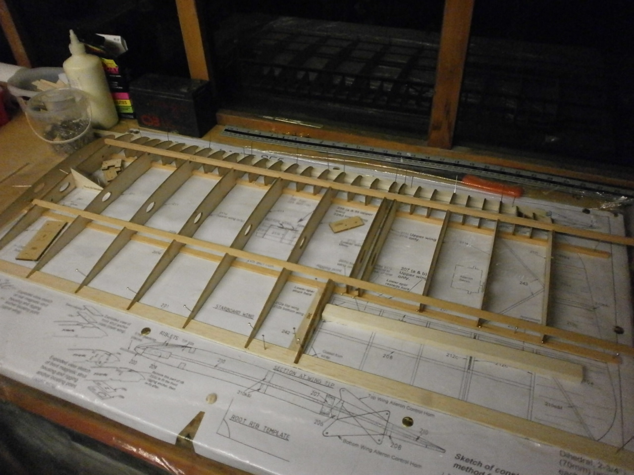
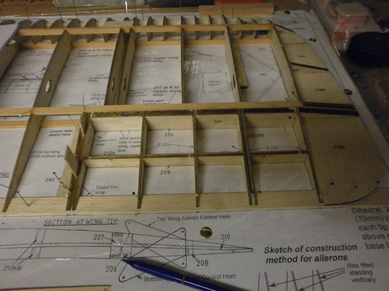
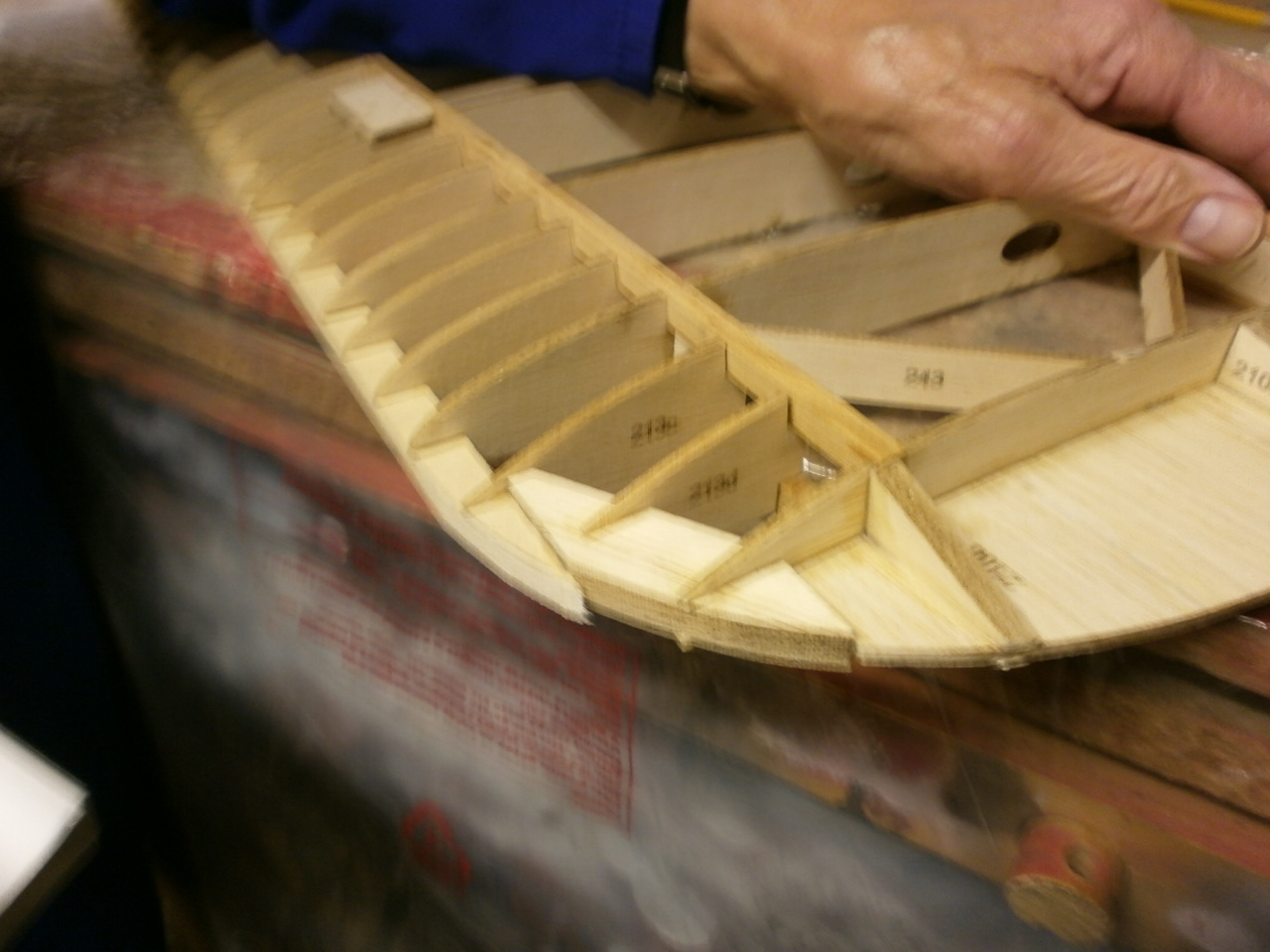
As you can see from the first picture below, there are a considerable number of parts that make up each wing section. It took the two of us a whole evening to locate and double check that we had all the right parts for the section we are intending to build and even then, when it came to the actual building it soon became apparent that we had missed off a few parts.
 |
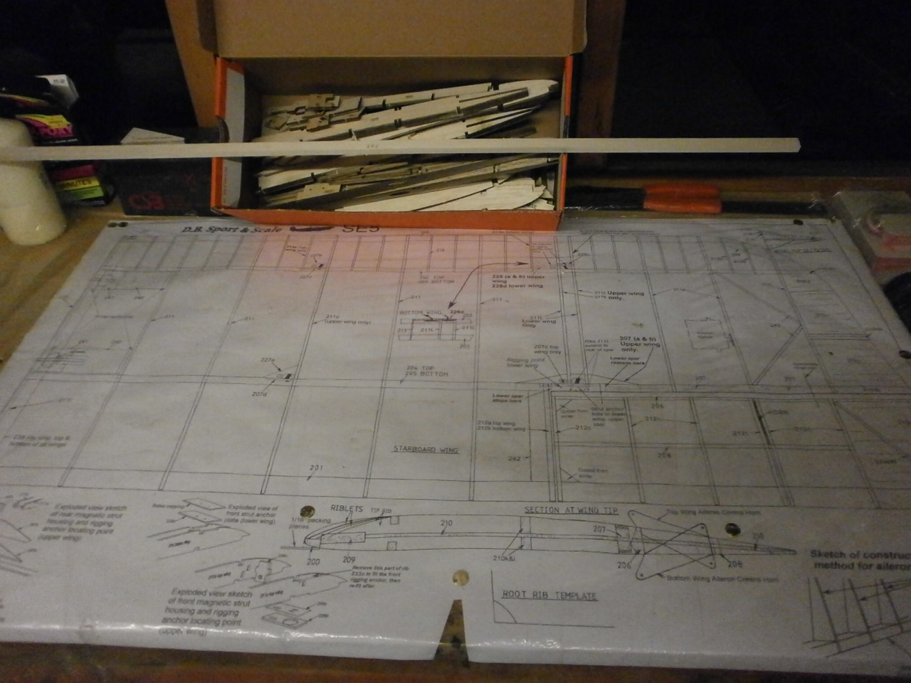 |
The first thing to do is to locate the spruce main and rear spar. These where laid onto the plan in their required locations. We decided not to pin them into position just yet. Next the leading edge was located and placed over the plan. It is required that this part rests on top of a packing strip of 1/16 Balsa to raise it enough so that once the rib and riblets are put into place they will marry up with the leading edge. Picture 2 below.
 |
 |
Once located into position this is pined into place. We now turned our attention back to the spars. Taking a selection of ribs that run the length of the panel and starting at the root we placed then into position over the main and rear spar whilst pushing the front of the ribs into position over the leading edge. By employing this method it ensured that when the remaining ribs are located they fit exactly over the spars and leading edge.
Once the ribs are dry fitted into place the spars are now pined securely to the plan.
Next as per the instructions, the root rib is glued into place and using the supplied dihedral template the rib is angled to its final position and pined. Picture 2
 |
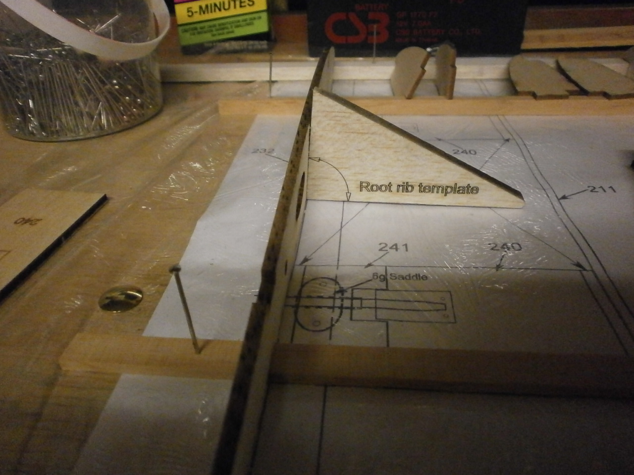 |
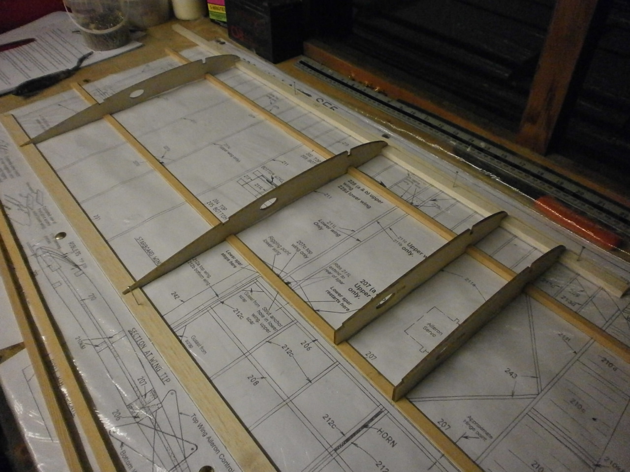
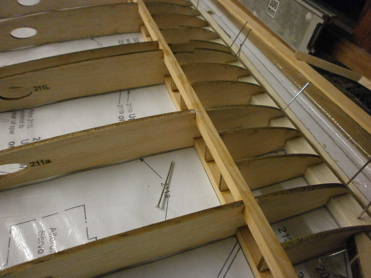
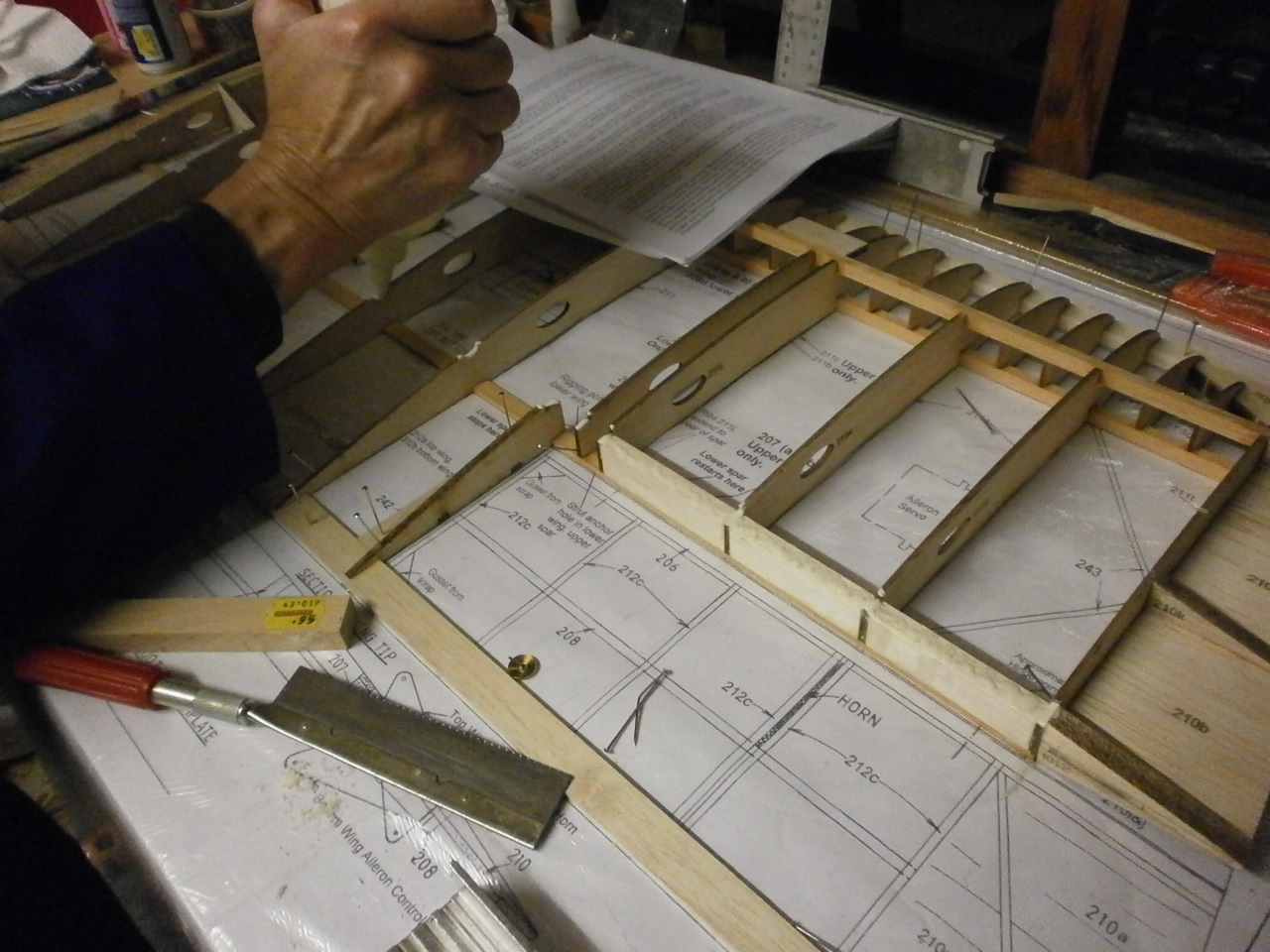
Next moving from the root to the tip, the riblets and ribs are located into position and squared up using a set square. pictures 1 & 2 below. As mentioned above, depending on whether your building the top or lower wing panel you will require different ribs so it essential that you check, double check with the plans that you have the correct rib for the panel you are working on. This also applies for the riblets.
 |
 |
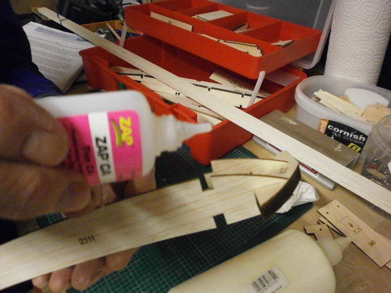
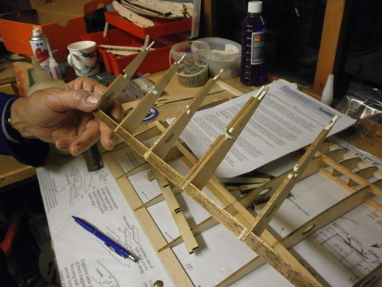
When the wing tip is reached there are ribs and riblets that need to be interlocked with a leading edge section before placing on the plan. The following pictures show these parts being bonded together and ready for location onto the plans. (For the general wing build we are using aliphatic glue, but for speed these part where glued using zap)
 |
 |
The following 2 pictures showing the components required two make up the wing edges where the ailerons start. Note that the trailing edge is in situ over the plans This was put into place at the same time we placed in the spars.
 |
 |
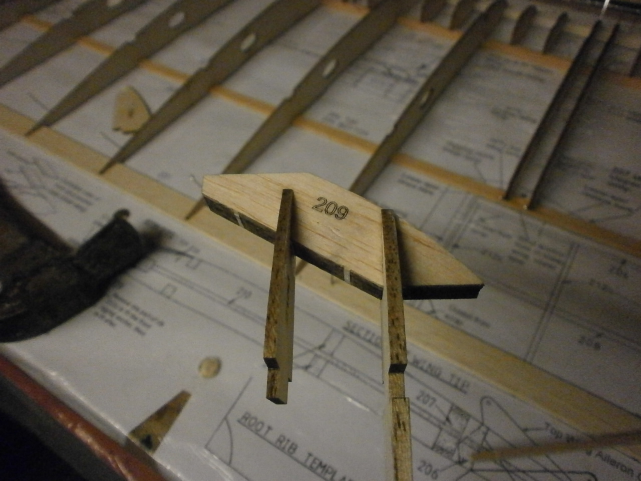
The next picture showing the basic
structure. Now it becomes a little more complex so we decided this
would be a good time to finish this session.
A fresh start will give us time to re-read the instructions and plans,
hopefully ensuring as we progress that we do not make any stupid mistakes.
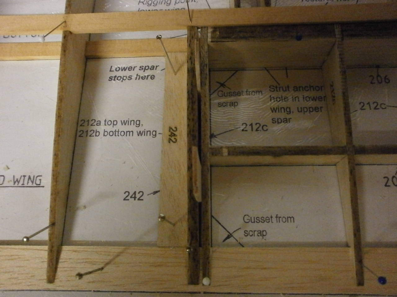
Picture 2 below shows after regrouping, taking the brave decision to place in the top main spar.
 |
 |
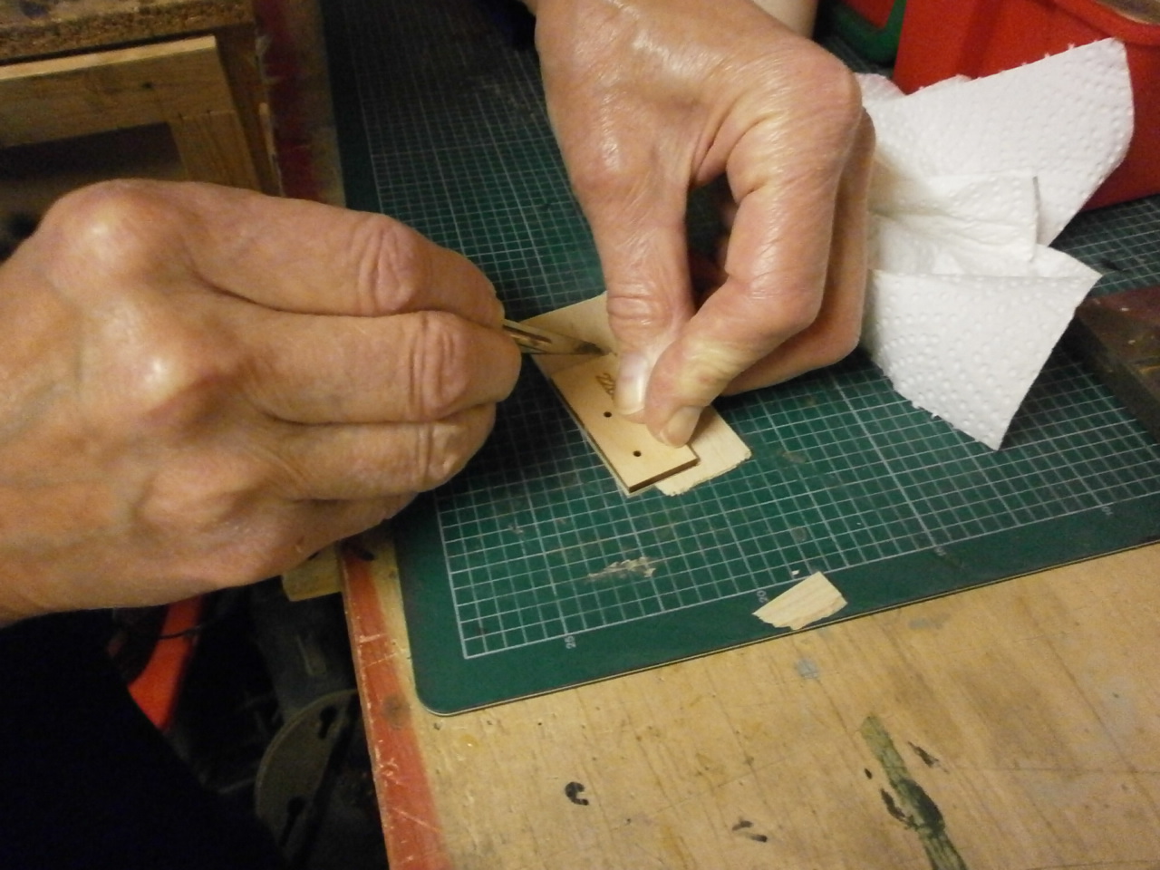
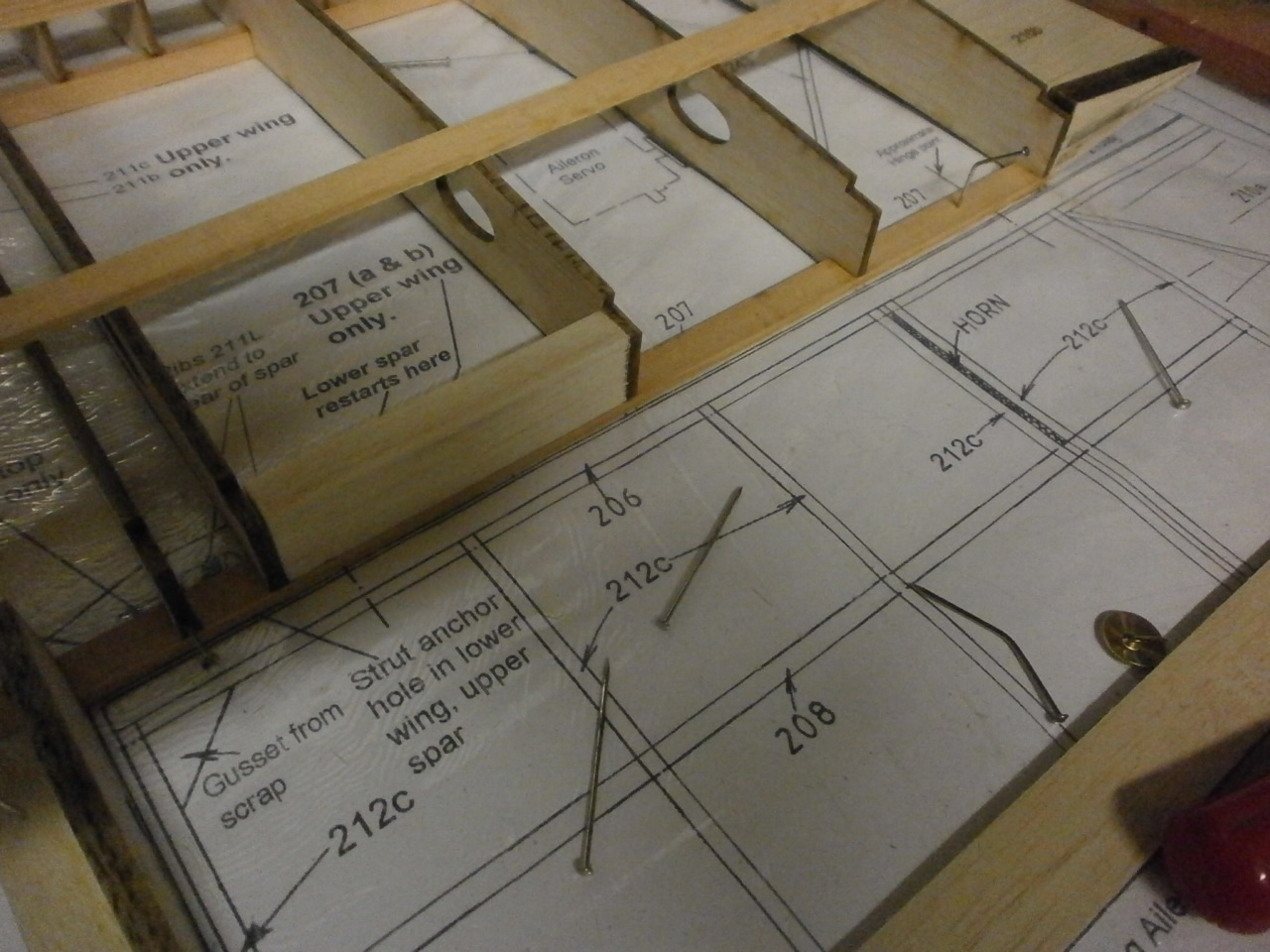
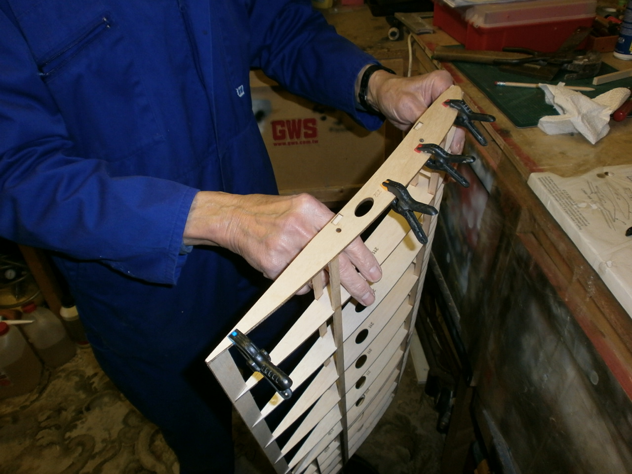
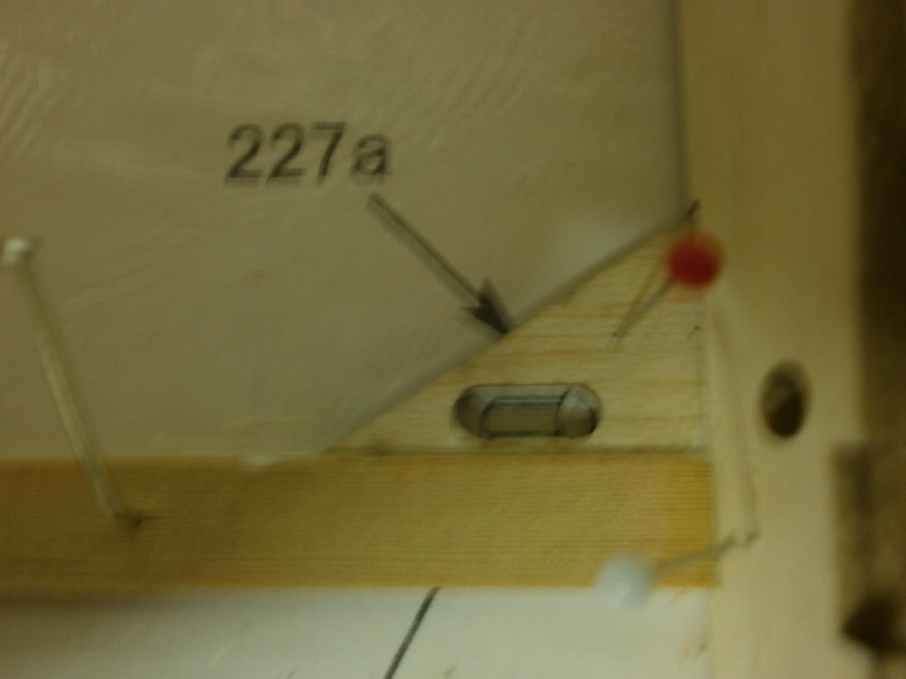
With this in place we then located the strut and rigging anchor plate. This needs to be laminated with a piece of1/16 Balsa sheet to bring it flush with the top of the ribs. Once this is in place it will stand just proud of the rib allowing the plate to be sanded to profile. See pic 1 below.
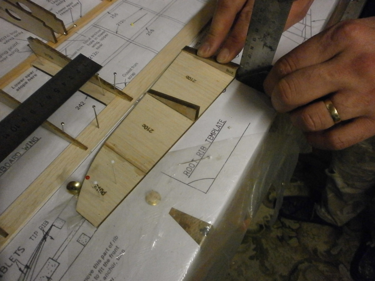
Nest we turned our attention to the wingtip section. This is made up of three pre cut balsa sections. These have to be butt joined together and to ensure that the edge that will be butted up to the wing tip rib is square a steel rule was employed to achieve this prior to gluing. Pic 2 below.
 |
 |
Once the above had cured we then add the wing tip support wedges both top and bottom again making sure that all was square. See pictures 1,2 below. This was then set aside to cure.
 |
 |
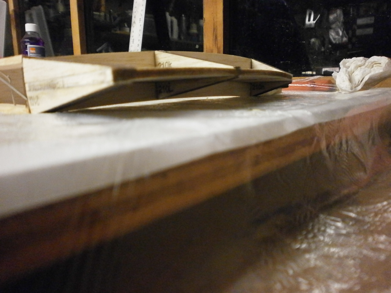
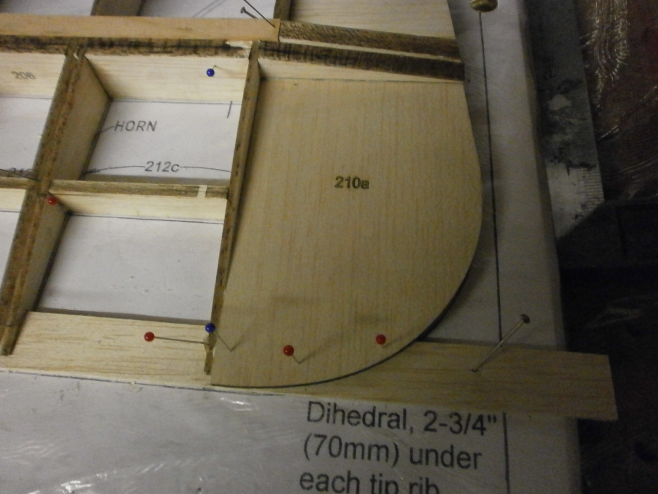
With the structure now cured it is offered into position making sure that everything lined up. Once happy we started zapping into place starting first at the leading edge butt joint and then systematically working back gluing at each support wedge at a time and then finally zapping the wing tip to the wing rib.
The first picture below showing the now installed tip. Note the slight curve in the tip. This is referred to in the instruction and also on the plans with an illustration of the curve in a cut through section of the plan. When we first looked at this we where concerned as to how we would achieve this, but if you follow the methods above ensuring that the wedges sit exactly at the top of the wingtip rib then this will automatically give you the required amount of curvature.
With this now complete we then added the aileron bay trailing edge pieces as per instructions. See next 2 pictures.
 |
 |
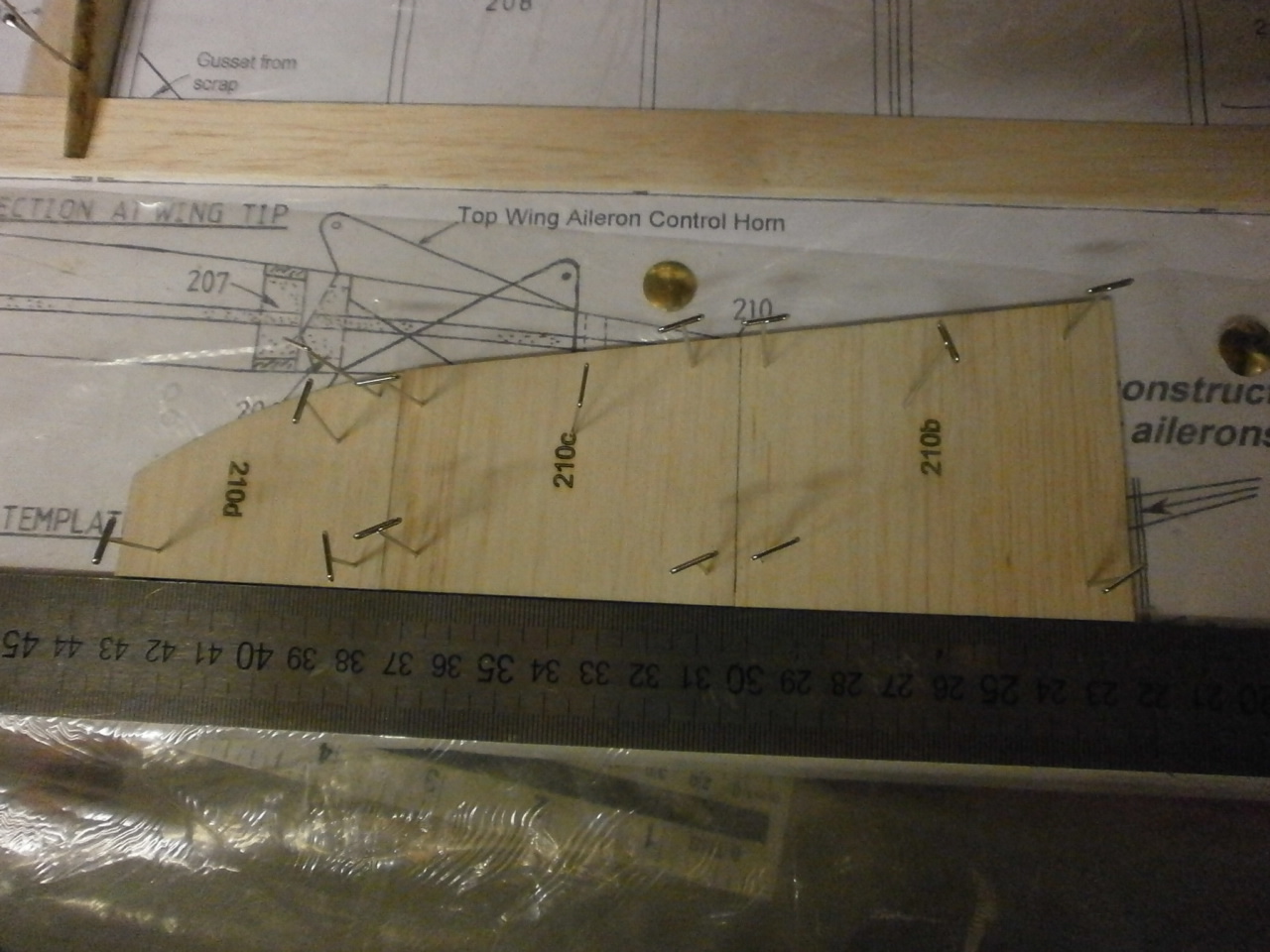
With this completed our attention turned to the ailerons. These are partly built of the plan with the leading edge spines being laid flat on the building board with the main ribs being interlocked into their positions, squared up and zapped. Picture 2 below
 |
 |
This structure is then offered over the plans and into the centre spar. To ensure that everything lined up and that we had an equal gap at the wing and aileron edge we used scrap 1/16 balsa sheet, which worked out to be just the right thickness. picture 1 below
The following 2 pictures showing the now nearly completed aileron in situ over the plan and with the aileron tip in place. Note that this sits directly over the trailing edge and will be sanded to shape as per plan and instructions.
 |
 |
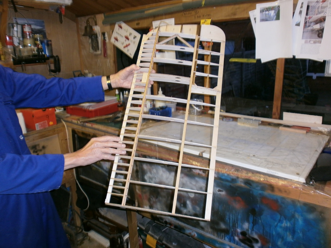
The last two pictures showing the wing now lifted of the building board and the 1/64 ply rib epoxied into place.
 |
 |
 |
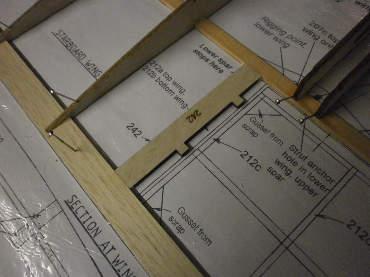
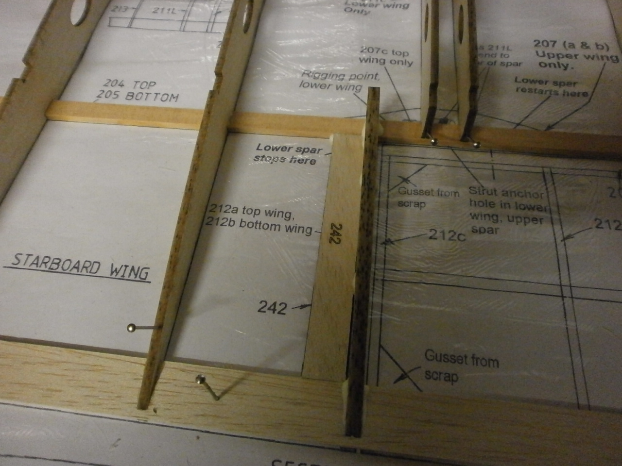
The top wing is made up over the same plan with just a couple of subtle differences. See the following pictures below. |
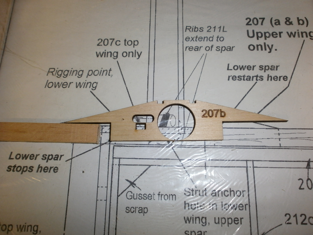
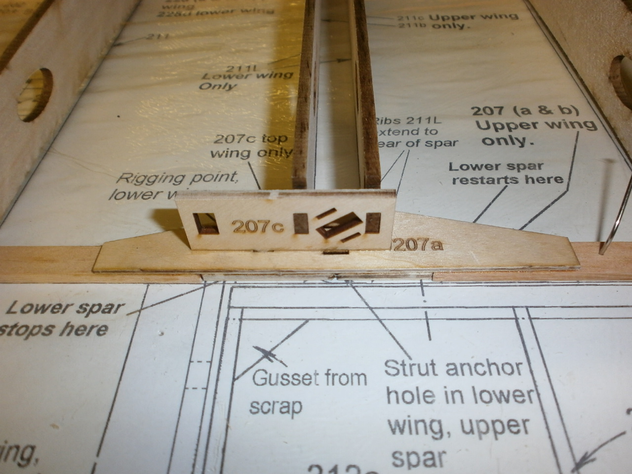
The first difference is the introduction of the lower rigging point ply plate. this sits between the lower spar which is spit to accept it. See picture 1 below with this epoxied into place then a further plate is laminated on top of this and the lower spars to re-enforce these joints. See picture two
Also in picture 2 you can see the other part installed that makes up this unit. The two ribs in place here are also numbered differently than that of the bottom wing, so it is essential that you double check everything first before you commit to gluing into final position.
 |
 |
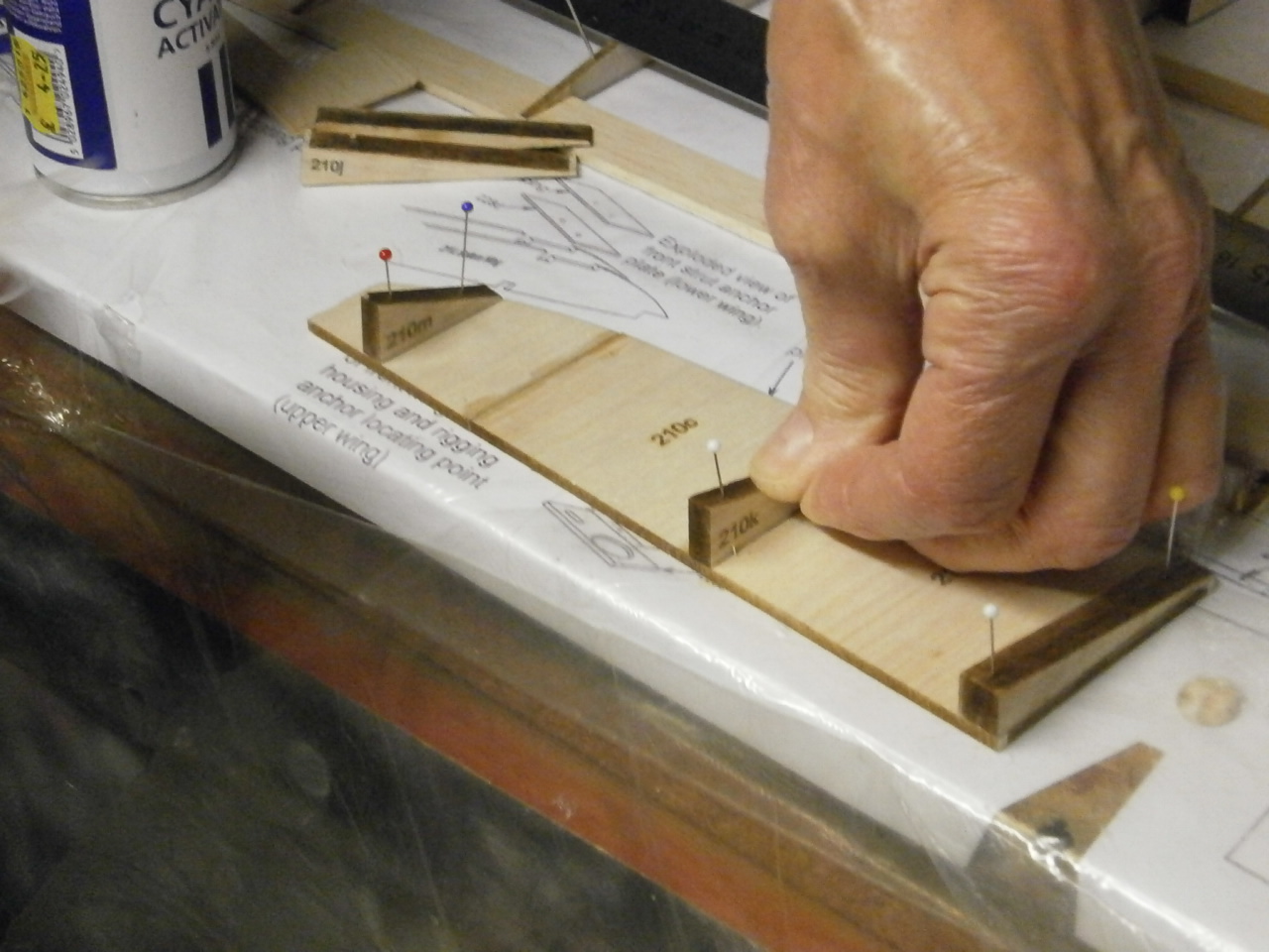
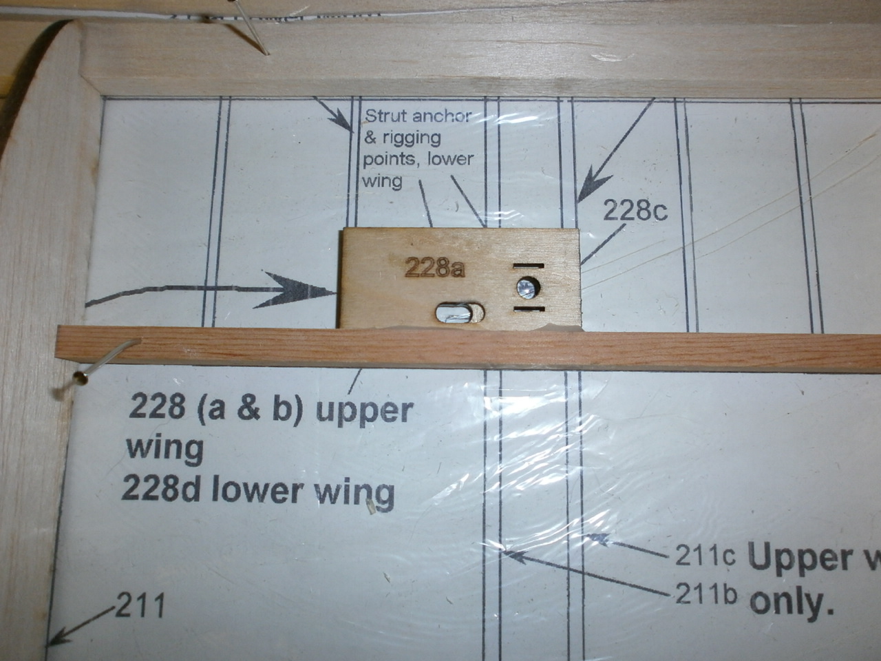
The following pictures showing the other differences to that of the bottom wing. These again are rigging and strut anchor points set towards the root of the wing.
 |
 |
The only thing to place on the wings is the wing root sheeting but we have decided to add these once the wing retaining system has been built-up and installed
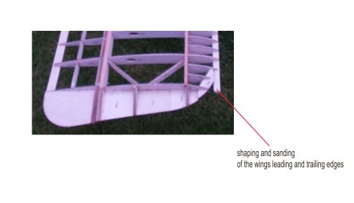
Wing sanding and shaping
With all the wing panels now constructed, our focus turned to the final sanding and shaping of each wing panel.
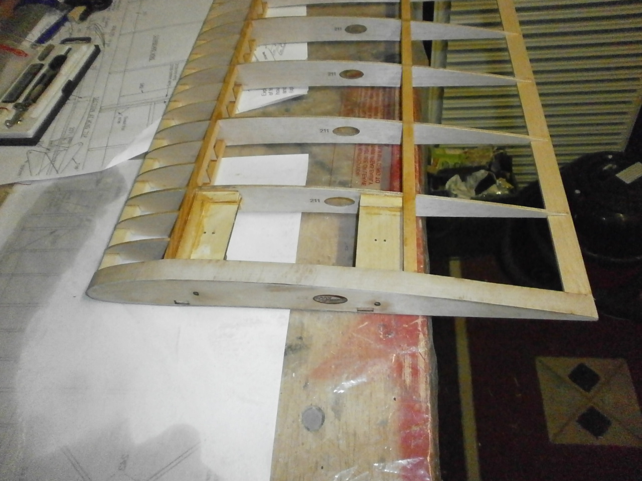
As you can see from the first picture below there are a number of areas on each panel that need trimming and shaping before final sanding.
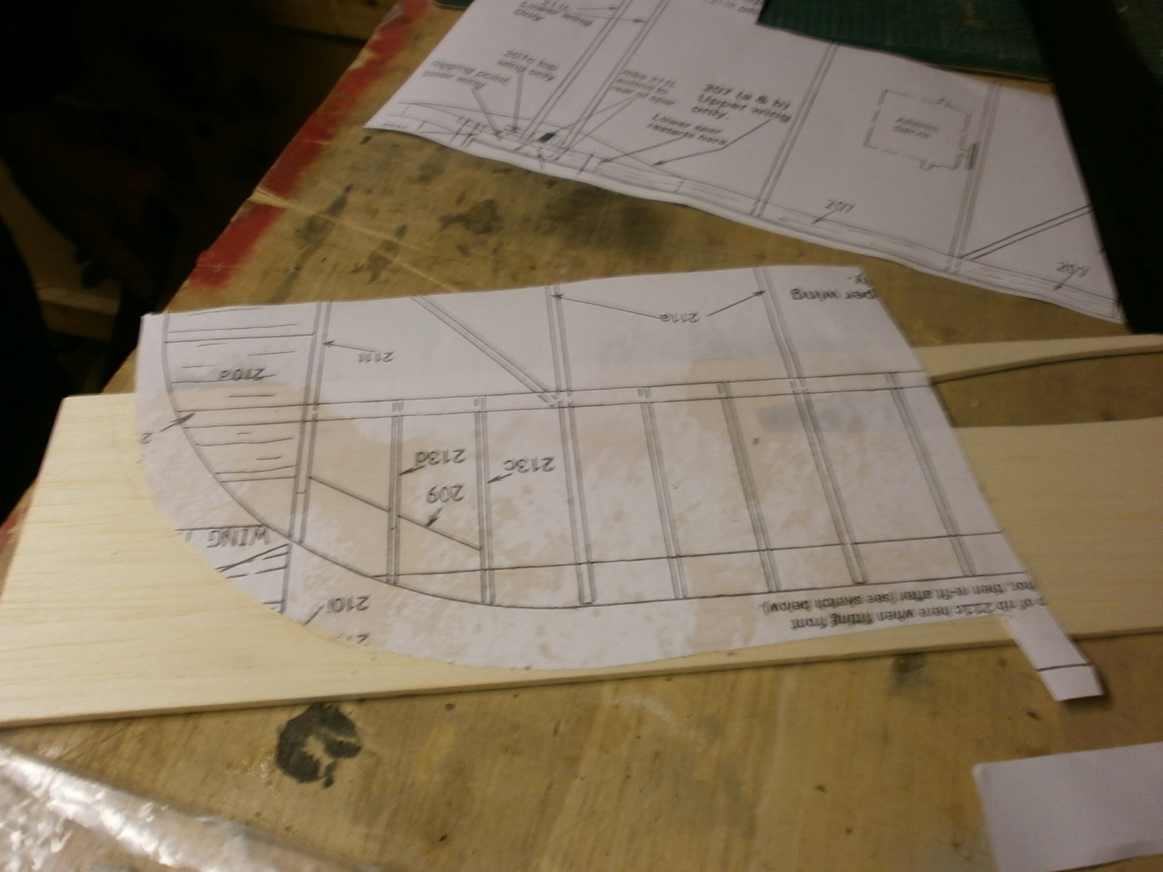
In the second picture you can see that we decided to make up a balsa template to aid in this operation. This will be offered over the offending over-cut of the wing tip section which was left during construction. This template enabled us to accurately mark out the correct tip profile ready for removal .
The template was made, simply by photo copying the section of plan and then sticking this to a piece of 1/8th balsa sheet and then carefully cutting out around the wingtip profile see picture 3 below. (note it is worth checking the photo copied sheet against the original plan for size, as some cheaper copiers are not always 100% accurate on scale)
 |
 |
Once cut the template is offered into position over the offending over-cut the offending piece is marked with a pen, giving us our cut line, pic 4 below.
 |
 |
With our cut line in place the offending over-cut is carefully removed with a craft knife making sure to keep it straight throughout the procedure. We tend to cut just outside of our line preferring to finish off with a sanding block to achieve the final profile.
 |
 |
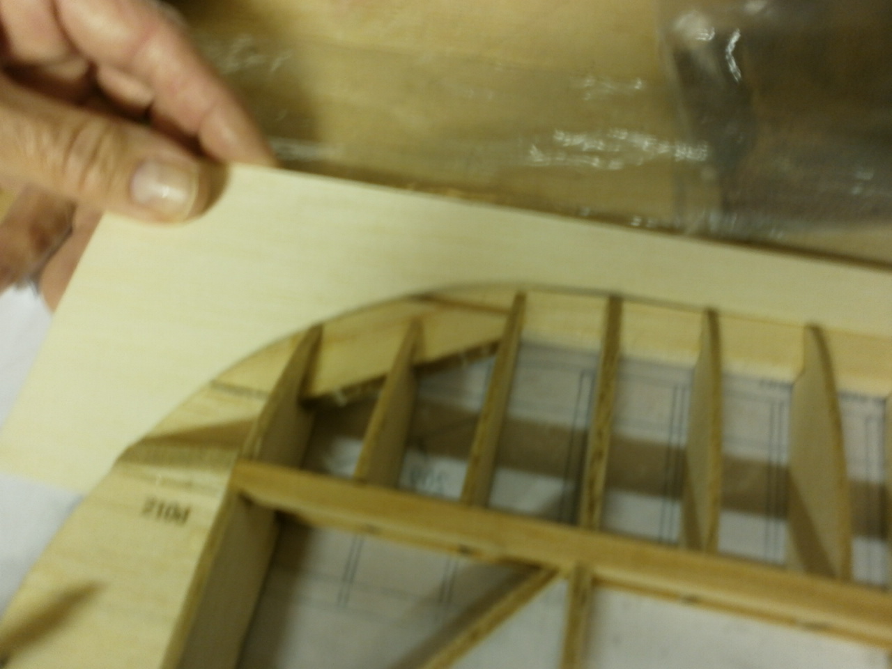
Once sanding has started we regularly place our template into position this helps in identifying any high spots and maintaining the requied profile. This process is maintained throughout and until we reach a perfect alignment / fit. See pic 1 below.
With the tip profile as per the plan we
next turn our attention to the shaping of the leading edge.
Again we make up a leading edge rib profile as we used for the wingtip.
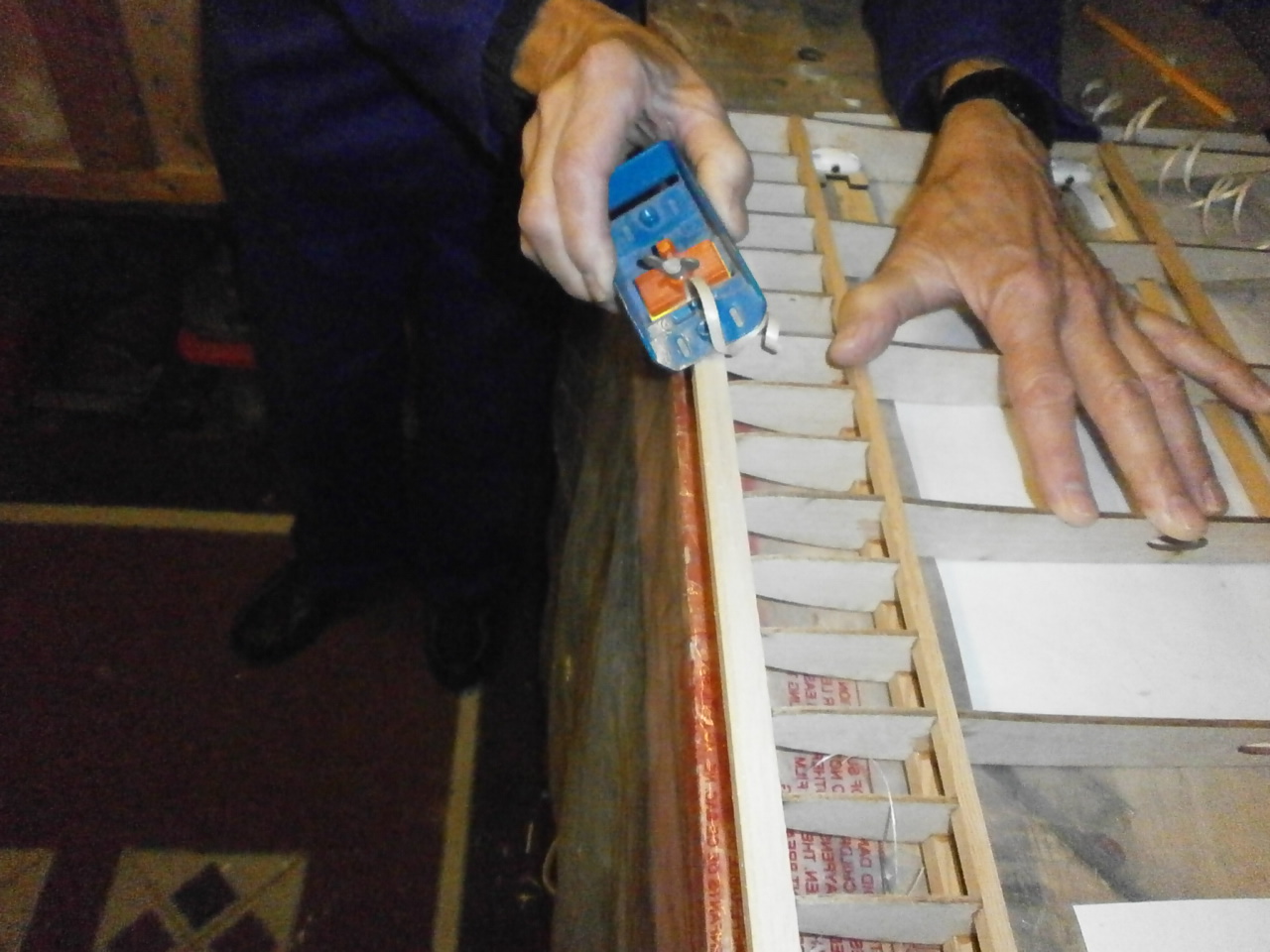
Picture 2 below showing the start of the leading edge profiling using a razor plane. This is used to acquire a rough profile and to remove the bulk of the wood.
 |
 |
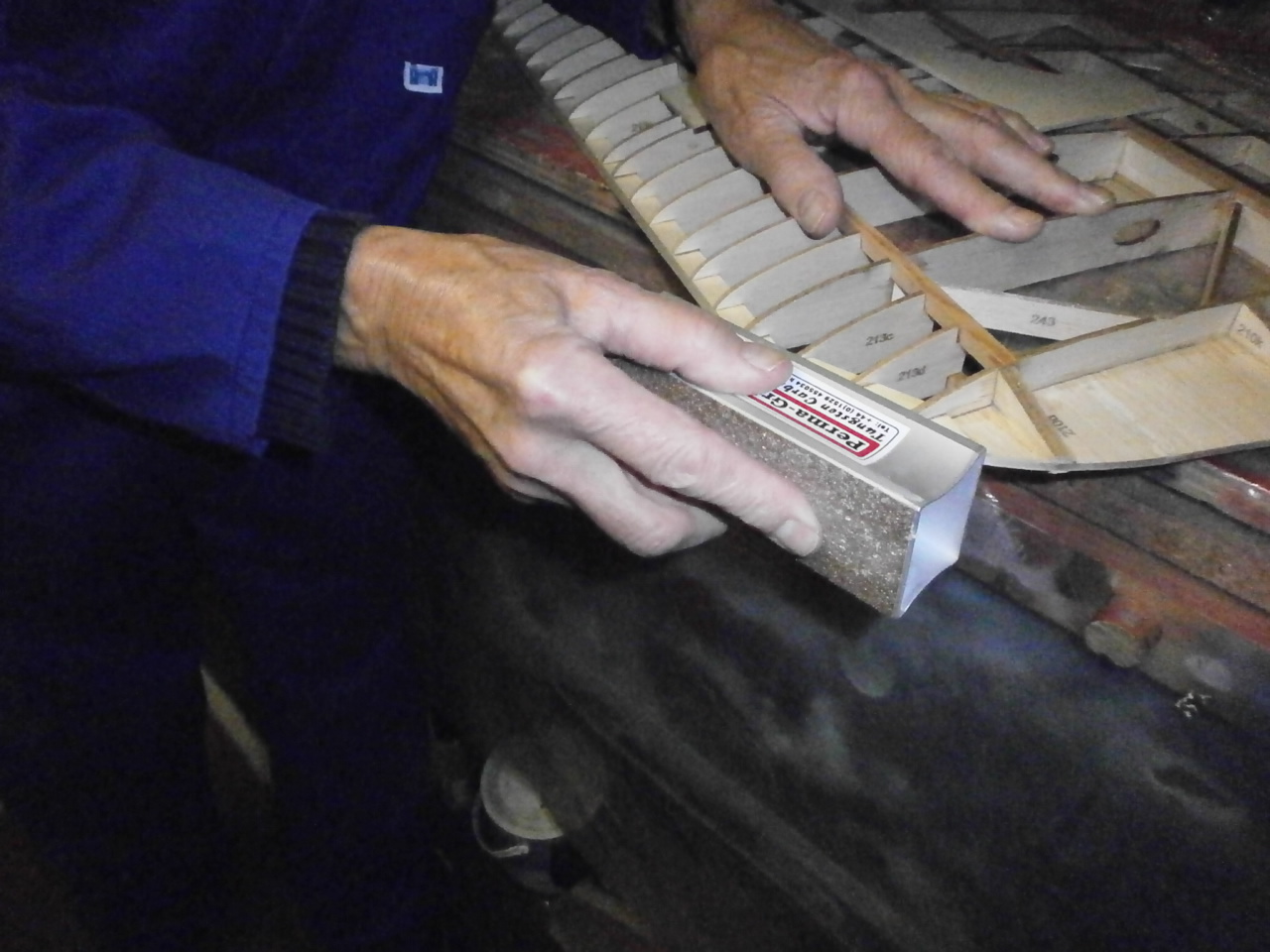
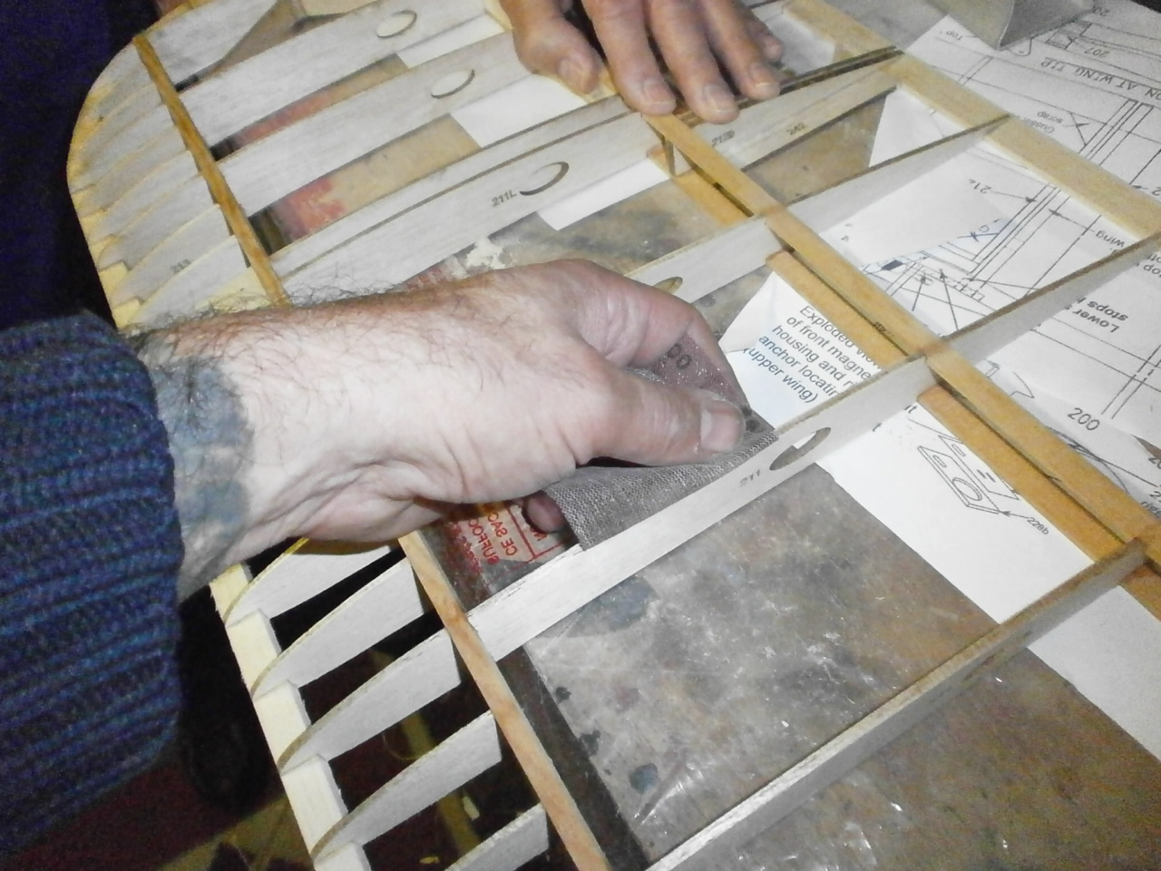
Once our rough shape is achieved we now switch to our sanding blocks. As you can see below a countered Perma grit block is used. Throughout the sanding process the leading edge rib template is offered up to the leading edge, making sure that required profile is maintained along the entirety of the wing.
Not shown in the pictures is the wing tip section of the leading edge. The detail on the plans does not show exactly how the profile runs as it comes out of the straight into the curved apportionment of the leading edge. This also on further examination, identified that the second from end tip riblet was somewhat shorter than that identified on the plans. After much deliberation a plan was put into practice and the correct profile for this area was achieved.
 |
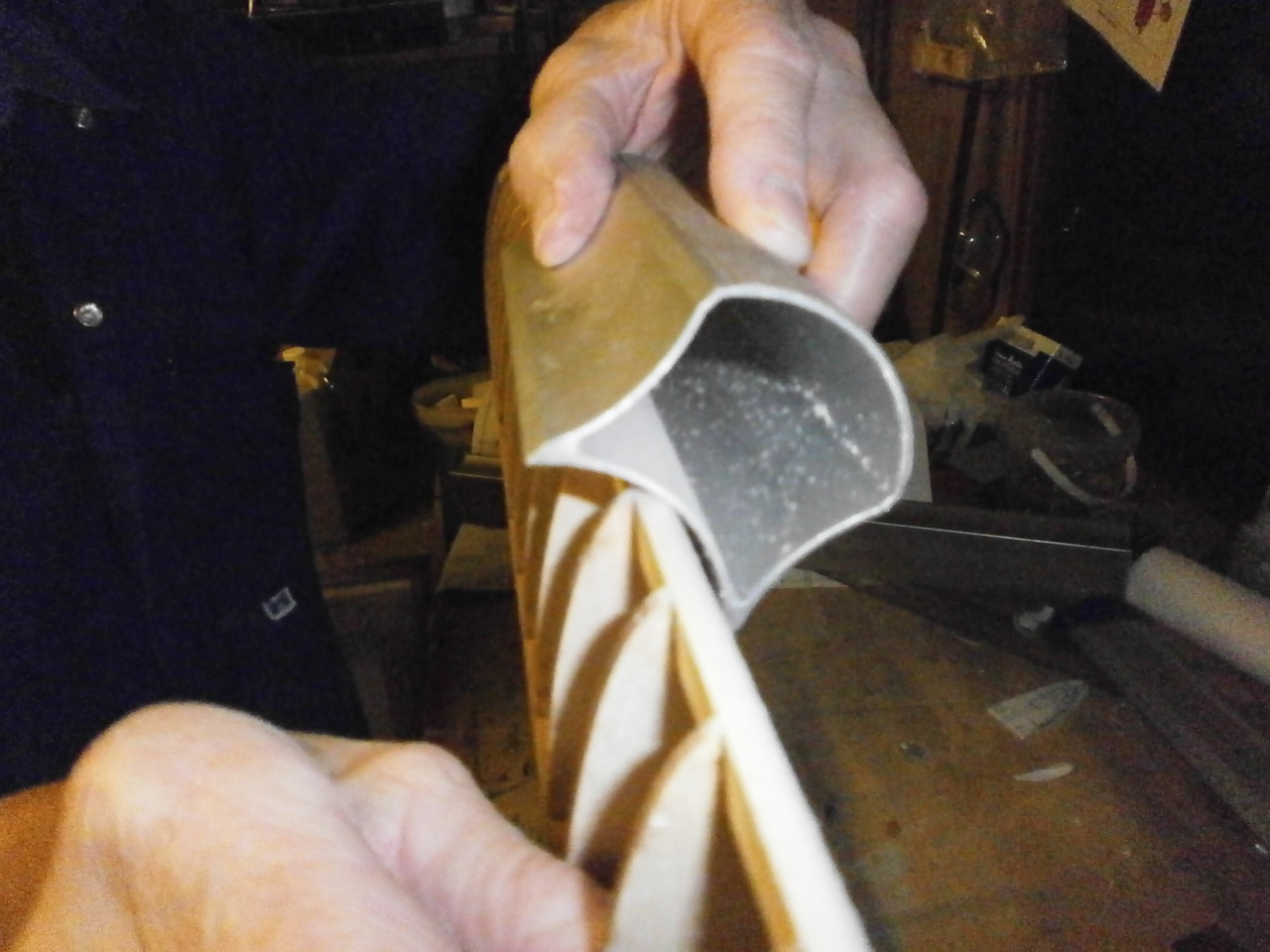 |
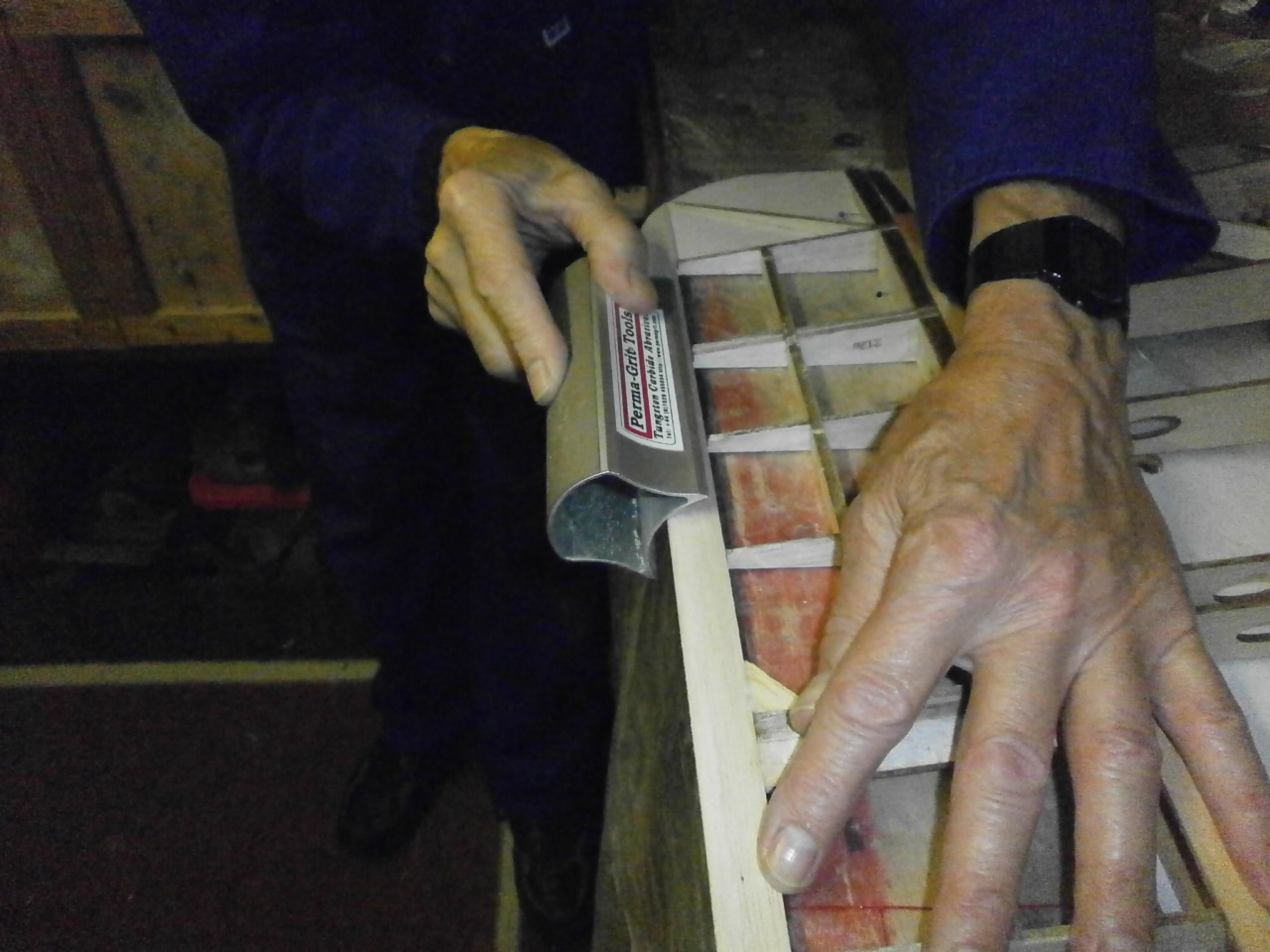
The next job now the leading edge has been completed is to concentrate on the trailing and wing tip edges.
On the full size aircraft these would have been made up from round cane / dowel. To achieve this effect again using our contoured sanding block we carefully sanded in the curve from both the top and underside of the trailing and wing tip edges respectively.
With all the major profiling sanding completed it was just a case of lightly sanding the entire structure and also placing on the root rib top and bottom ply sheeting strip. See pictures below.
 |
 |