Covering
Follow this page to see the covering of the Sopwith Pup.
Generally the methods employed for covering the individual components of the model will be similar, but I will endeavour to demonstrate the differences of covering both small and large areas.
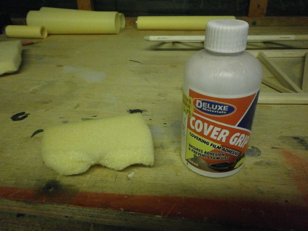
Before I start applying the covering (in this case solartex) I like to apply a film covering adhesive. There are different brands on the market and they all do the same job so my advise is to experiment and pick the one that suits you.
There are a couple of ways this adhesive can be applied, brushed on or sponged on and again it up to your preference. As you can see from the pictures below mine is to sponge on.
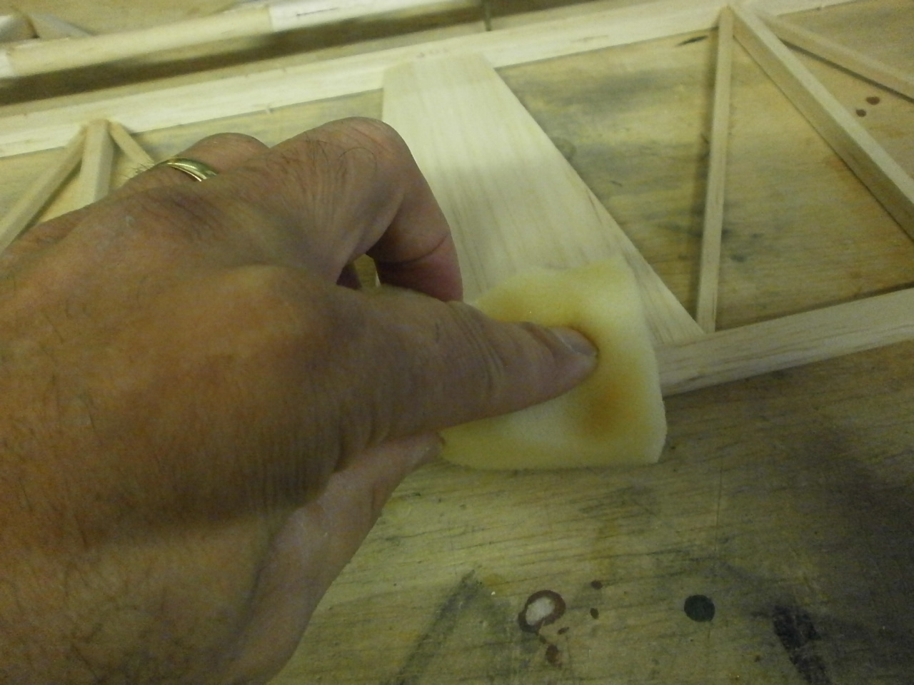
If you use this method then you will also need latex gloves.
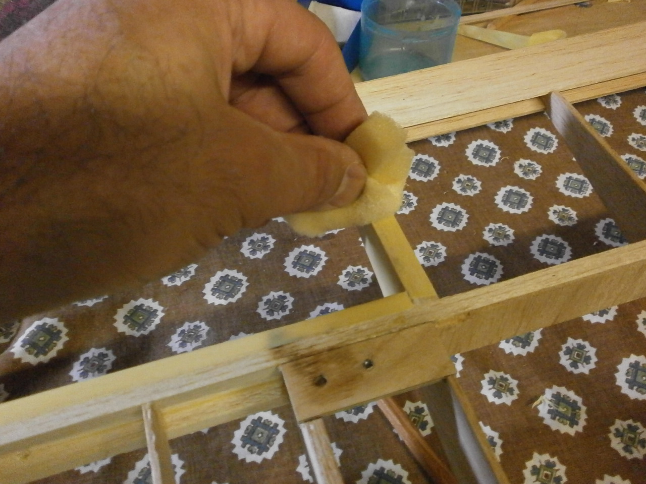
The procedure I use, is to pour a small amount of adhesive into a small pot and taking a piece of sponge about 3inches by two inches. Dip the sponge into the adhesive making sure that it does not become saturated.
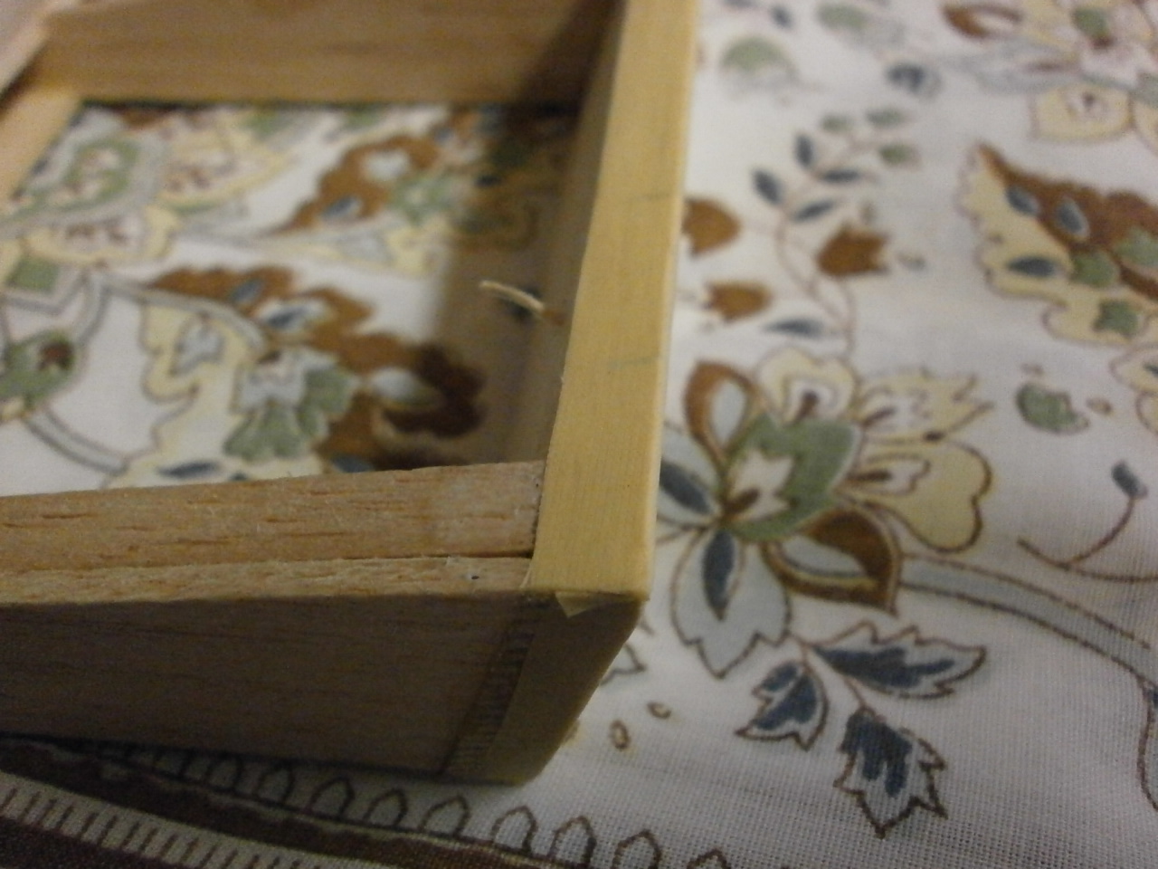
Now gently rub over the balsa structure (in this case the elevator )making sure that all the surfaces that the covering will contact are coated. The aim is to get just enough adhesive onto the wood without leaving heavy patches of adhesive, as when dried will leave unsightly ridges when the covering is applied. Pay particular attention to the edges of the structure ensuring that the covering will get a good grip when applied
|
|
|
Using the method described above has the added advantage that the adhesive will dry a lot quicker than when applied with a brush.
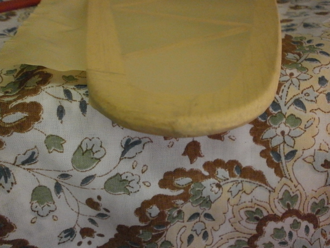
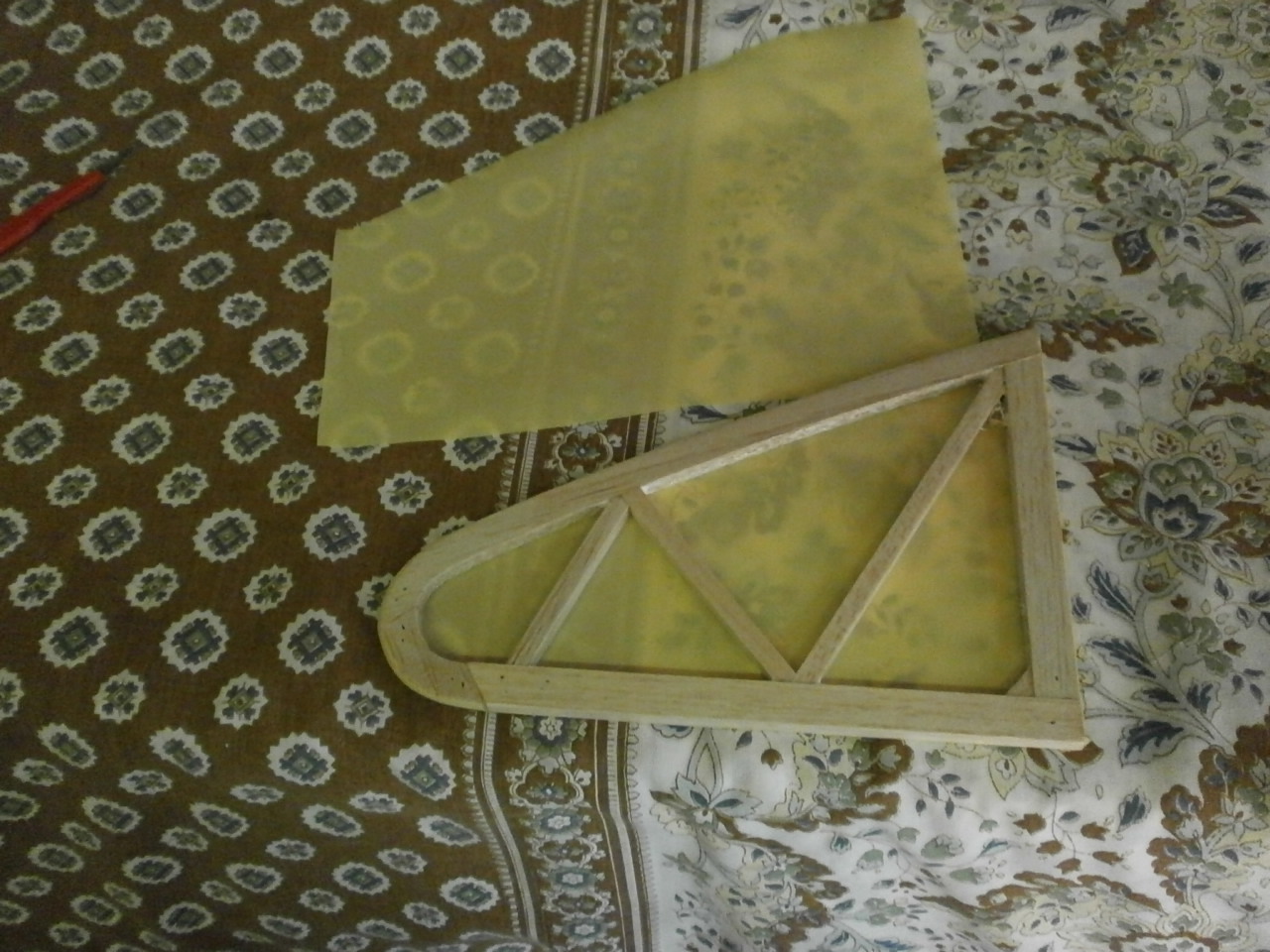
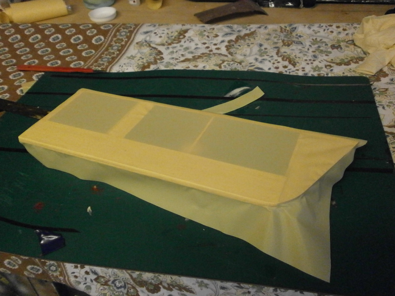
Once dried we can start placing on our covering. The first thing to do is cut the covering to size. This is easily achieved by unrolling a length of covering and placing the part to be covered directly over it. Cut around the part leaving approximately an inch overlap all the way around.
Depending on the covering your using there may be a backing film protecting the adhesive on the back of the covering. Remove this and place the coving onto the part making sure you maintain an even overlap all around.
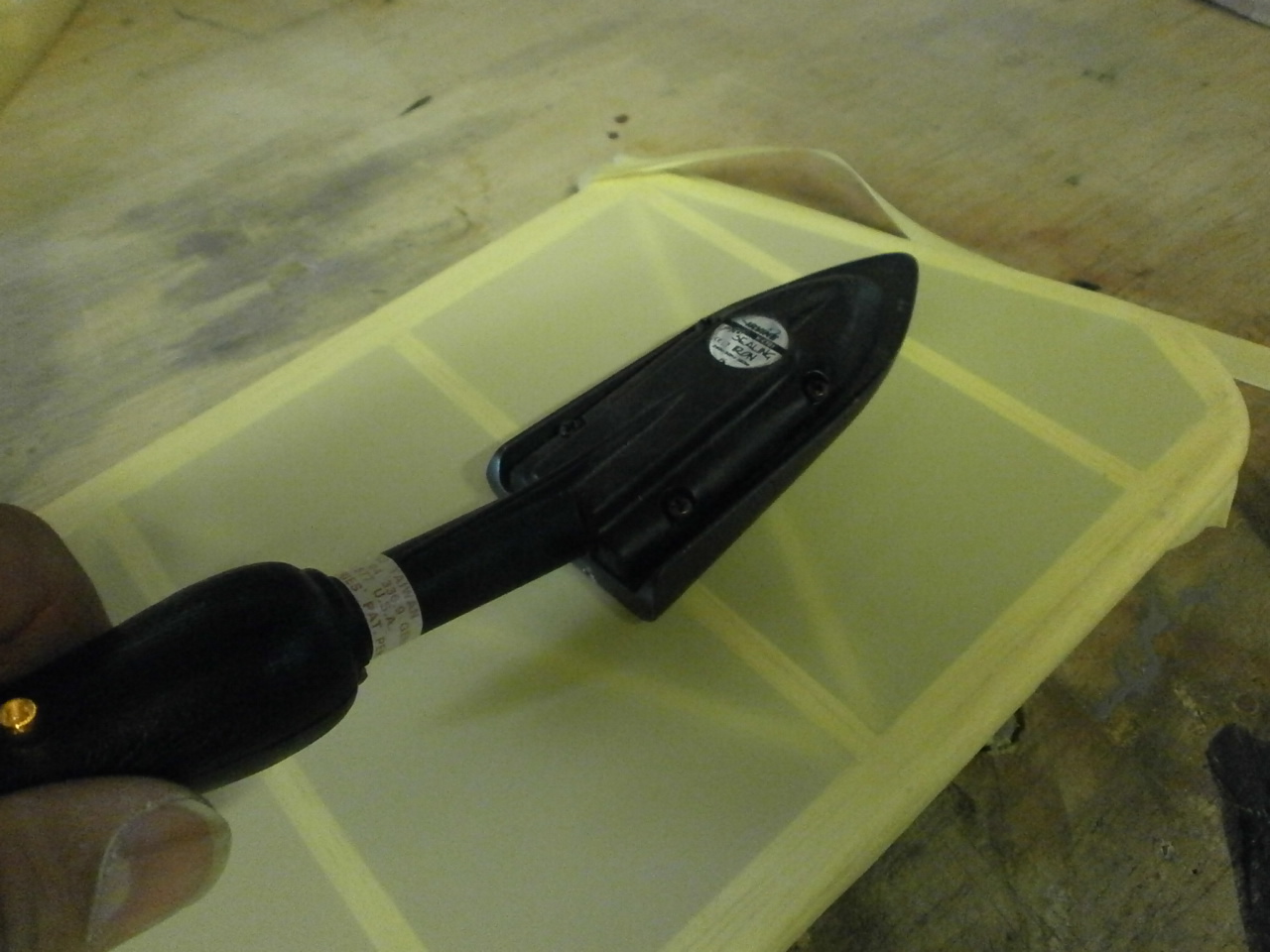
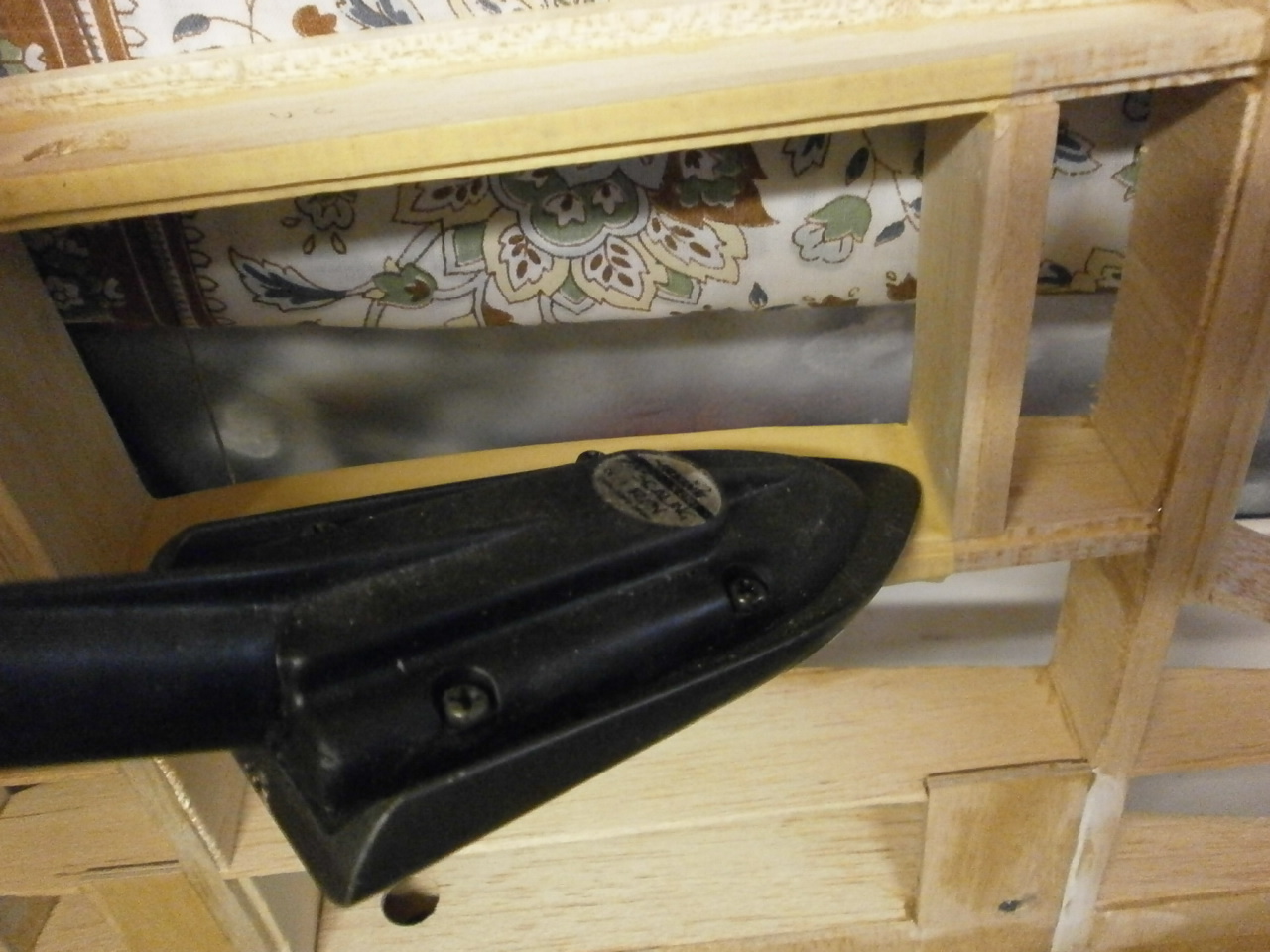
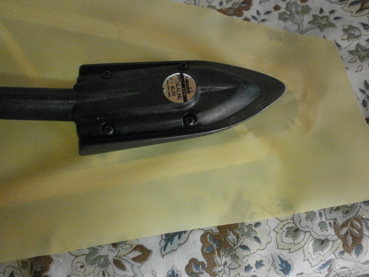
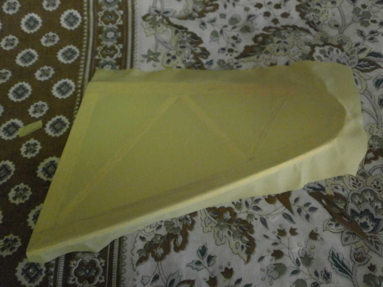
Next turn on your covering iron or wife's iron (if brave enough ) and set the heat to 100c. Once up to temperature gently tack one end either side and then working from one end to the other tack points either side at about 3inch intervals depending on he size of your part, making sure you do not introduce any large ripples. Having done that now run the iron as in he picture below along the middle of the part. you may notice that around the sides of the iron as you move down a few small ripples may appear, don't worry these will disappear as we progress. Now bring the iron back to where you started but this time working from the middle out in a diagonal motion repeat the process working alternately on either side.
Now we can concentrate on the edges. This is quite simple
for straight edges. All that is needed is to fold the covering over and apply
the iron to the material making sure that you do not introduce any creases along
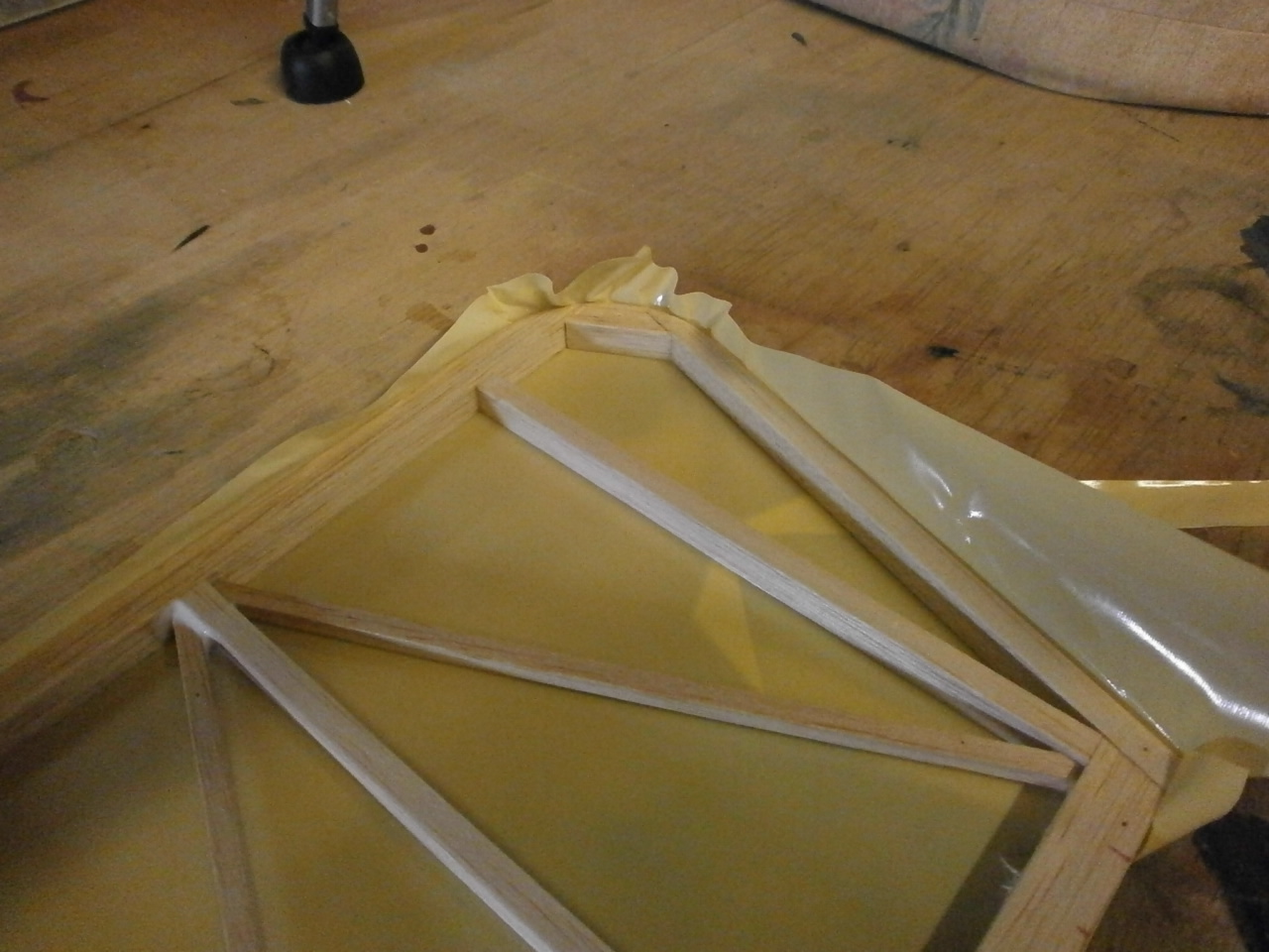
the way. For curves it is a little more complex but the principle is the same,
except this time we need to heat the iron up to 150c. At this temperature (the
final stretching temp) the covering becomes much more pliable and therefore
workable. With the covering in one hand and the iron in the other (worth getting
help here) gently pull the covering around the curve whilst applying the iron to
the curve and covering. Be patient when doing this and you will be rewarded with
a curve that is covered with absolutely no creases.
Once you have finished the
curves, you can then on the same heat run around the entire edges of the part to
finally seal the covering. Now turn the part up so that the underside is showing
and with a scalpel trim the access material away. Turn the part back over and
carry out the same procedure as before firstly working straight down the middle
and the diagonally from side to side one end to the other to shrink the covering
to a drum like finish.
|
|
|
Repeat the above procedures on the other side of the part again ensuring that the edges are firmly heated down before applying the final heat to the surface.
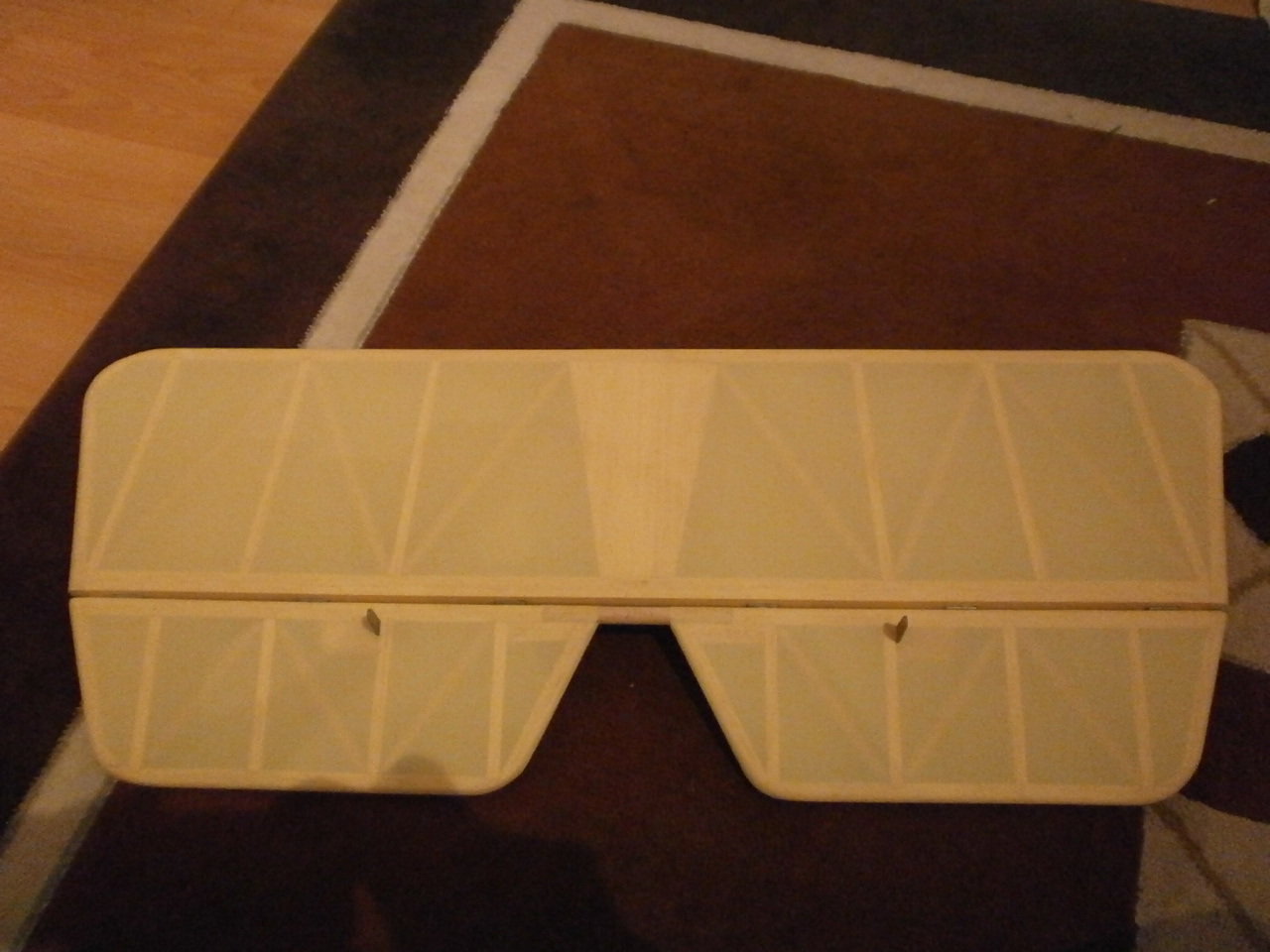
Pictures below showing first one side covered and the both
 |
 |
The same principle is used for smaller pieces although the smaller they are the trickier they can be
|
|
|
covering video
|
|
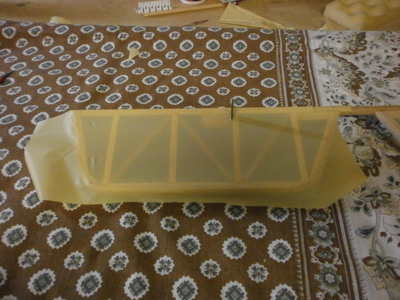
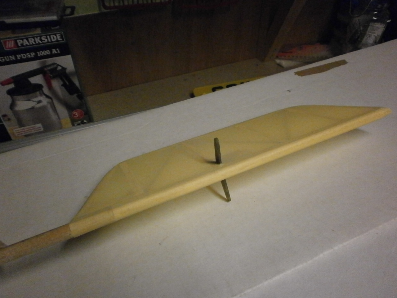
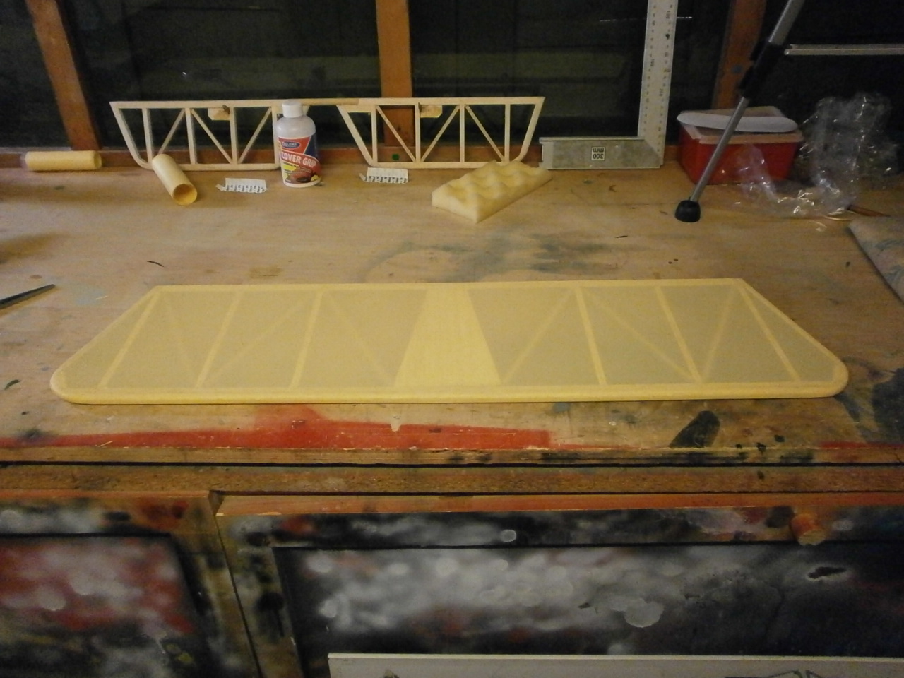
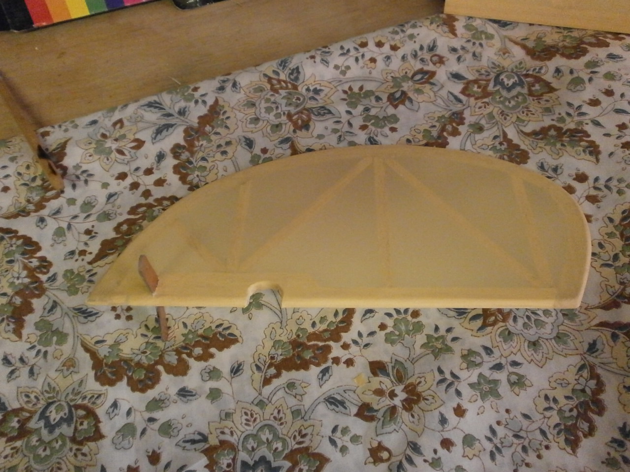
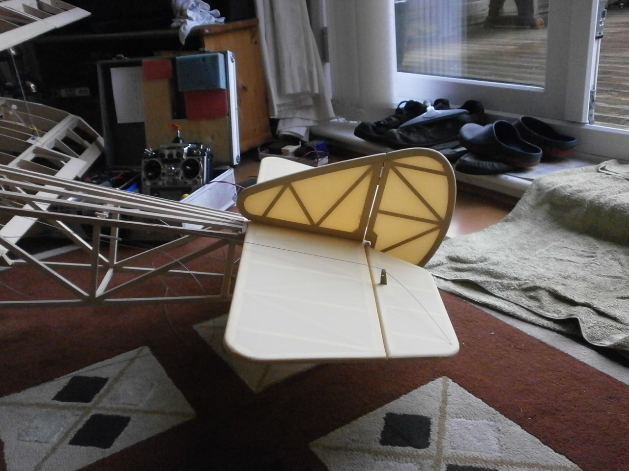
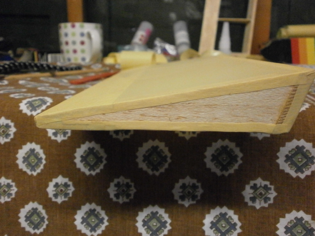
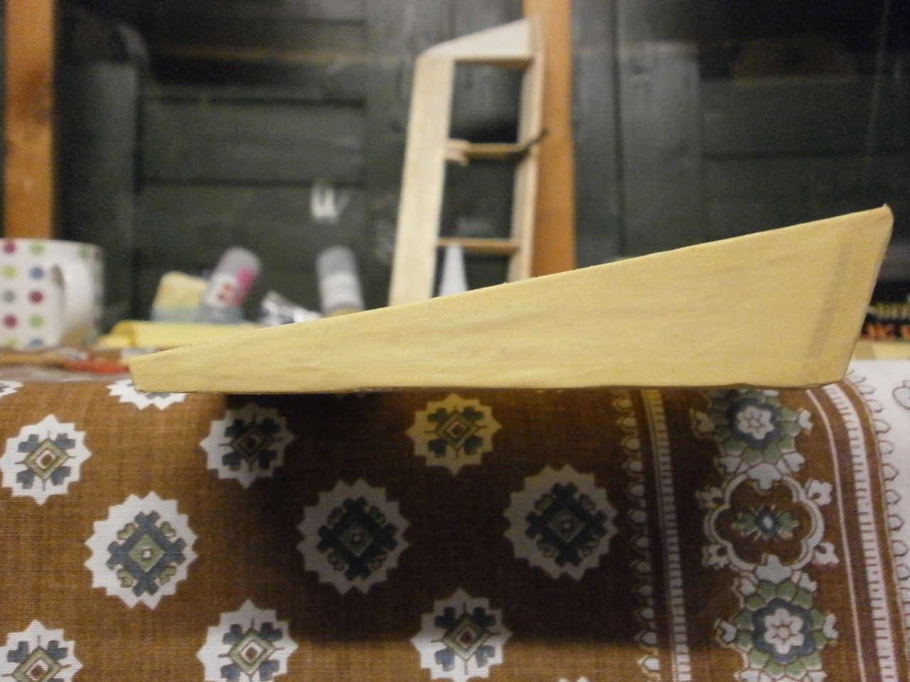
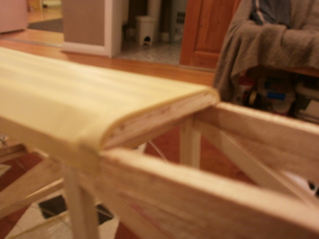
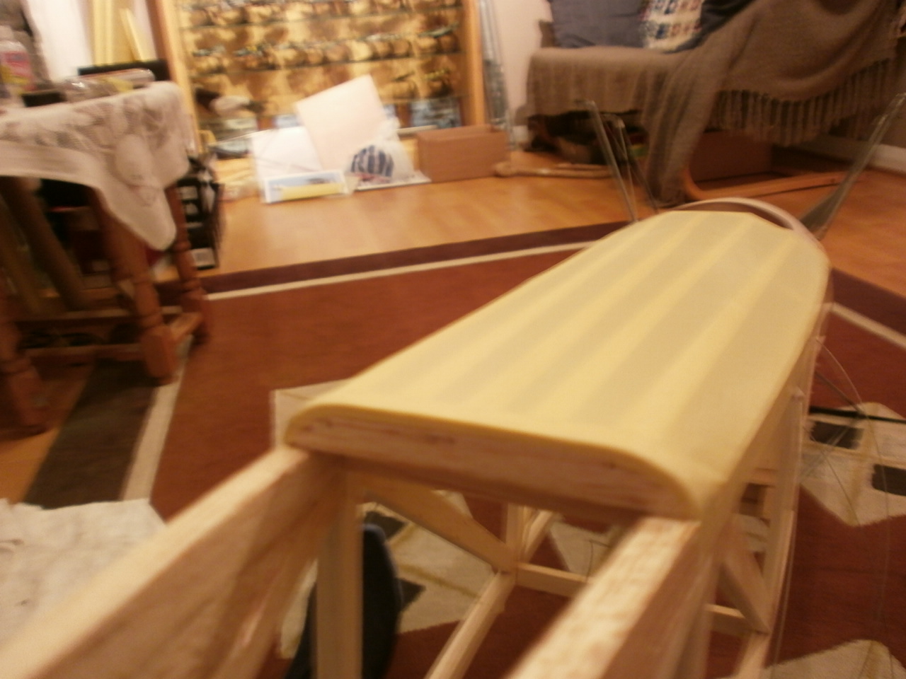
This picture is the completed tail section using the methods described above |
Below are a number of pictures showing the fin rudder and elevator covering using the same principle as above
|
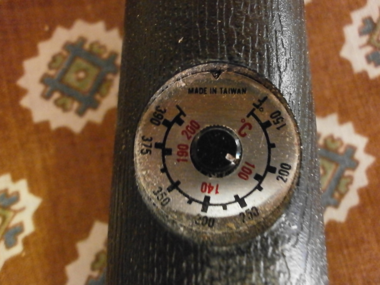
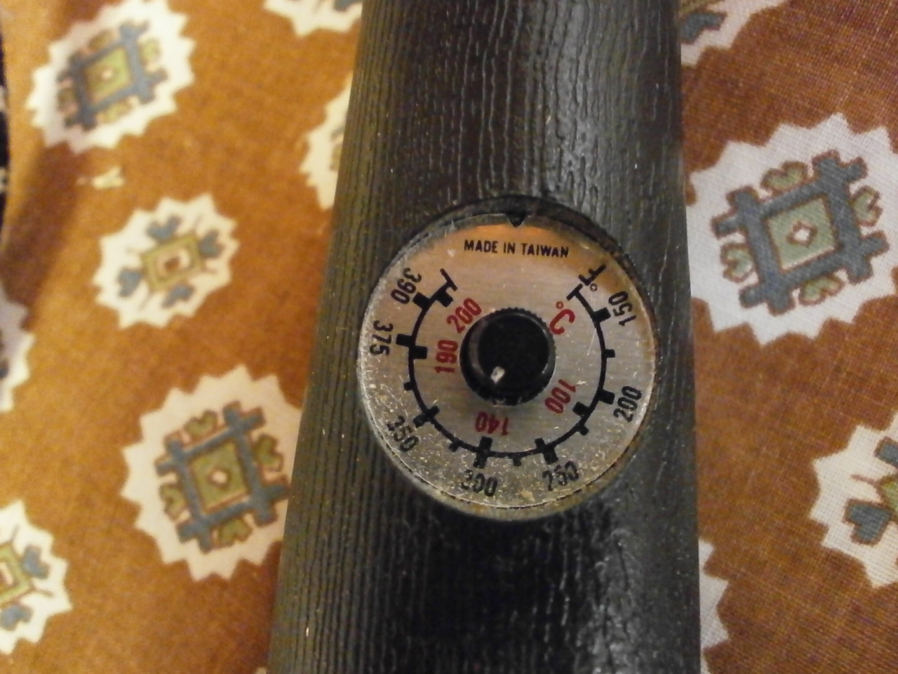
Iron temperature control |
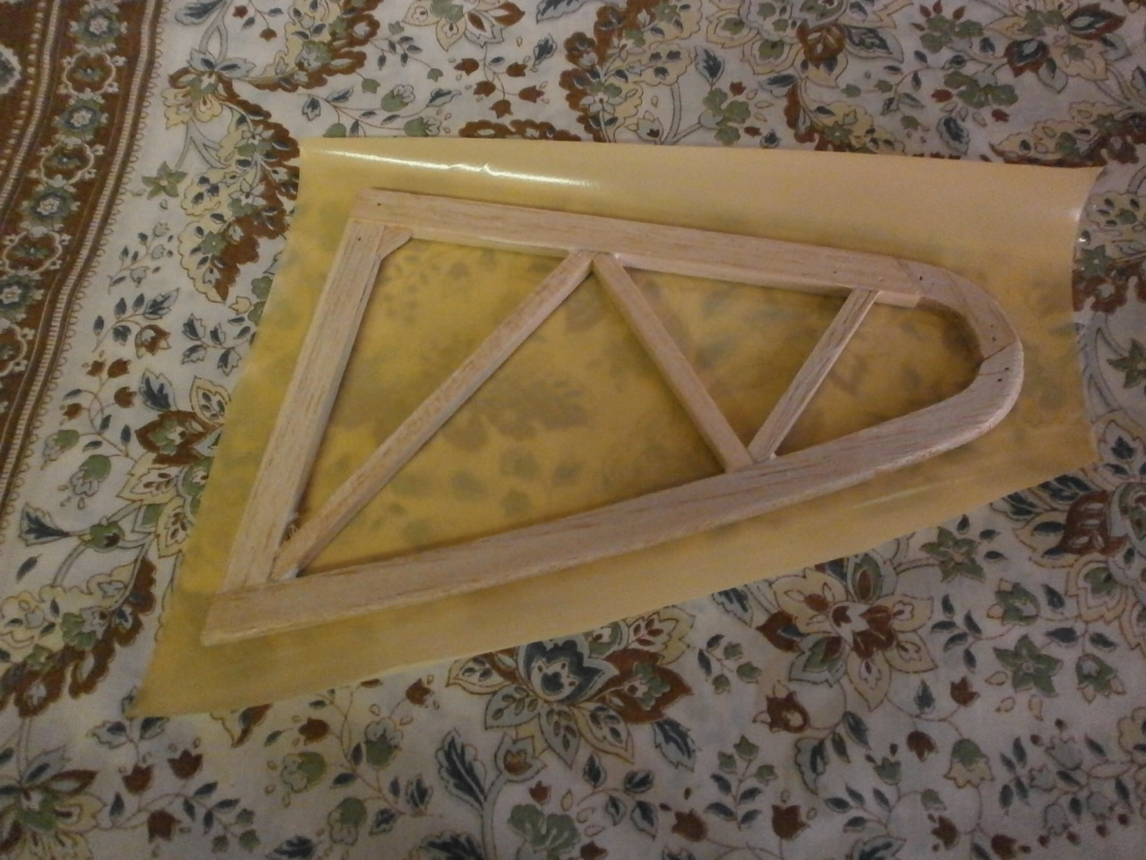
Solartex cut to shape |
 |
 |
|
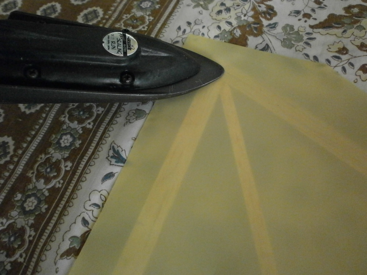
Covering tacked into place low heat |
Covering shrunk by running iron down middle and the from the middle diagonally out to the edges |
 |
 |
| Ends cut to allow folding over of edges | Temperature increased once edges folded to allow for the covering of curves |
 |
 |
| once sealed overlap removed | Curve covered note no wrinkles |
 |
 |
|
Fin turned over and same procedure carried out as above |
|
 |
 |
|
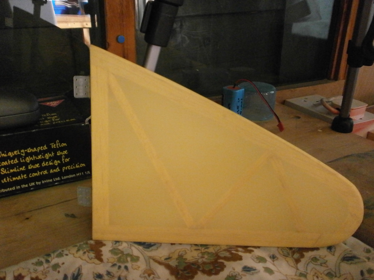
Completed fin |
|
|
Rudder
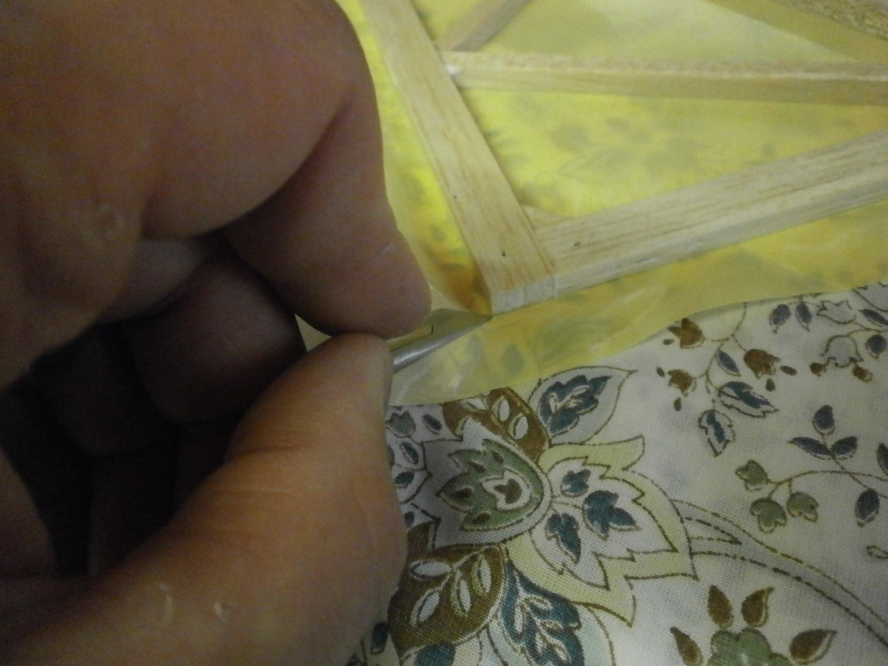
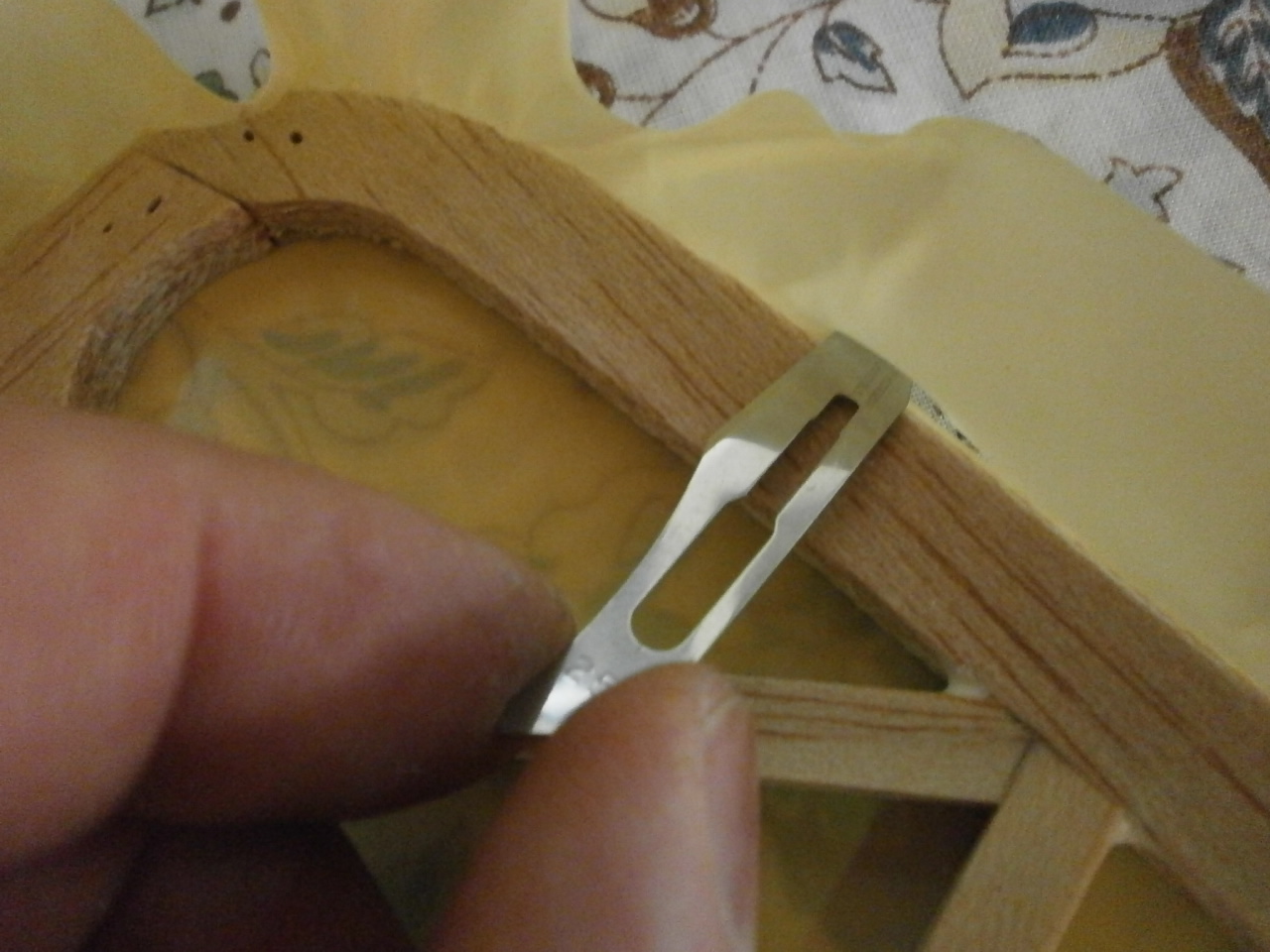
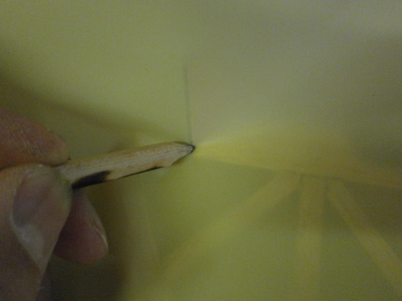
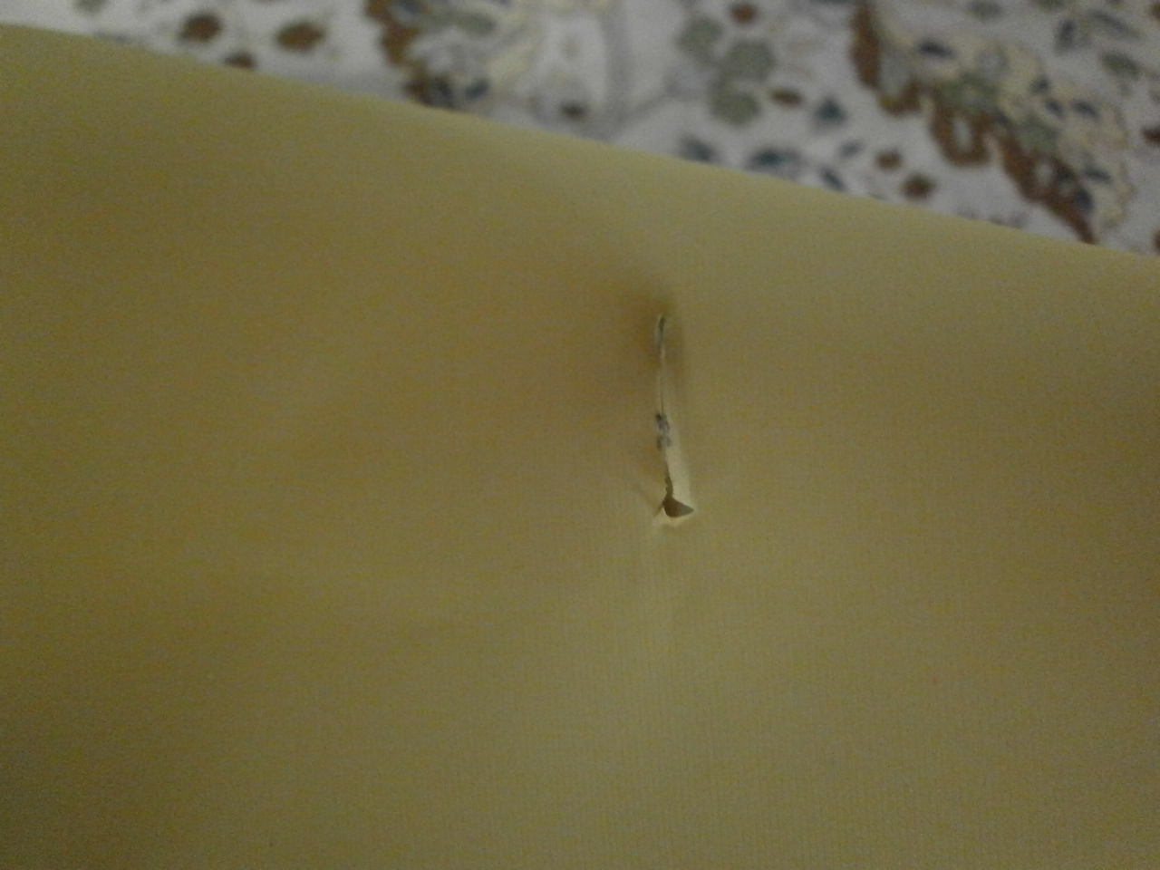
The rudder is covered exactly the same way as the stabiliser and the fin except, we need to cut a slot in the covering to allow the control horn come through. This is easily achieved by taking our pre-cut section of covering and aligning it over the rudder frame with an equal amount of overlap all the way around. Then with a pencil mark the covering at the point where the horn needs to come through and with a scalpel cut a slit slightly smaller than the width of the horn see pictures below.
 |
 |
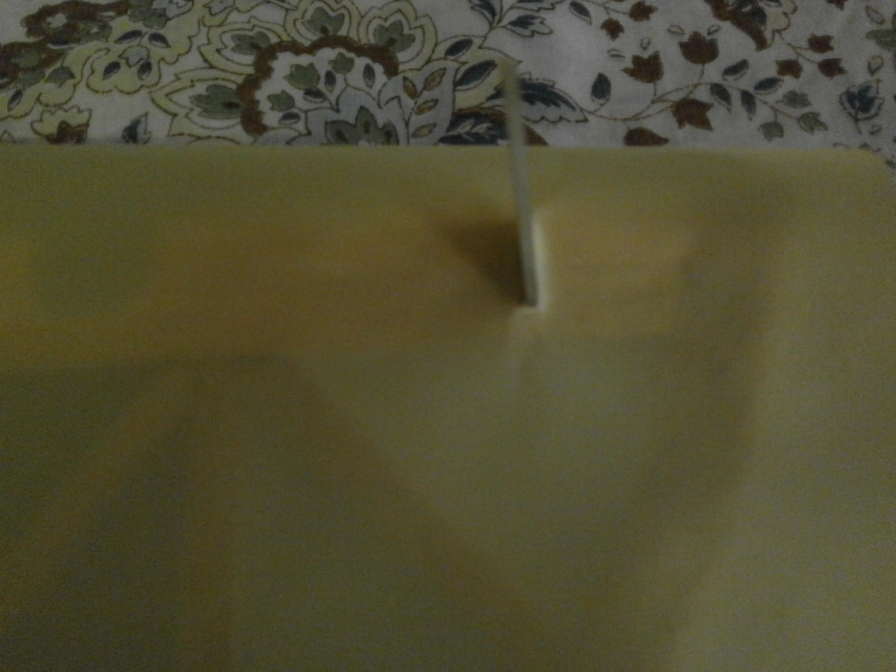
Now take the covering and push it over the horn and down into position. As you can see from the first picture below this gives a nice tight fit. All that is left to do now is finish the covering process as described above
 |
 |
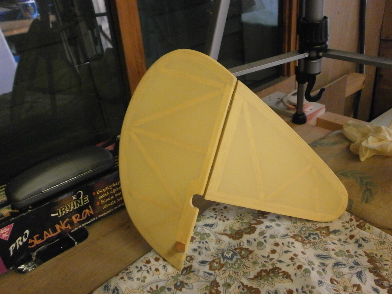
Pictures of the rudder and fin now fully covered and also mated up with the stabiliser sitting on the fuselage
 |
 |
Below a series of pictures showing the various stages of covering the ailerons
 |
 |
 |
 |
 |
 |
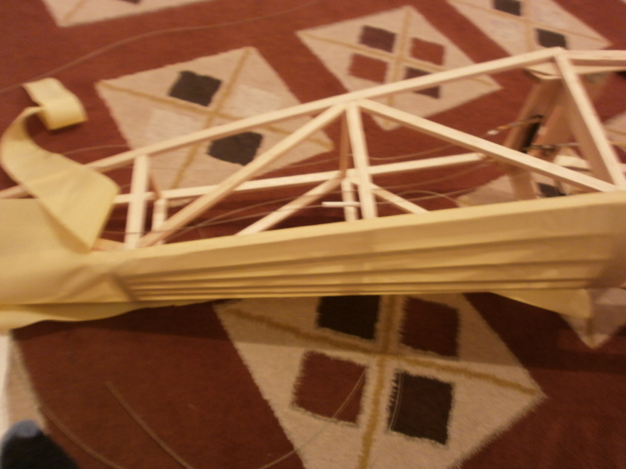
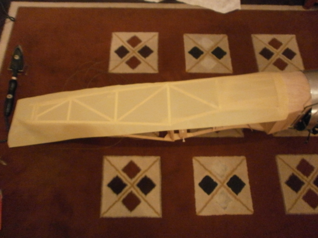
Wing covering
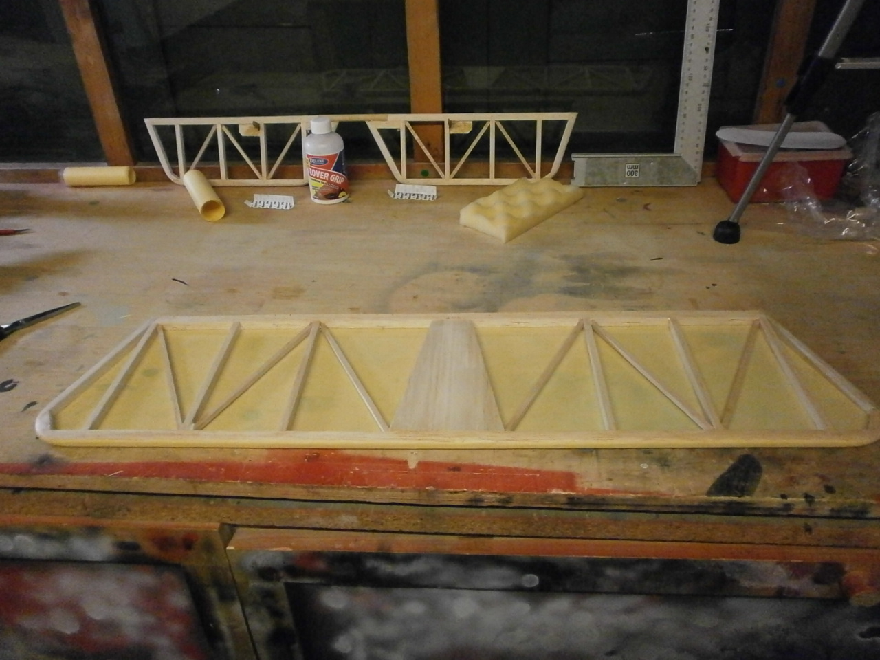
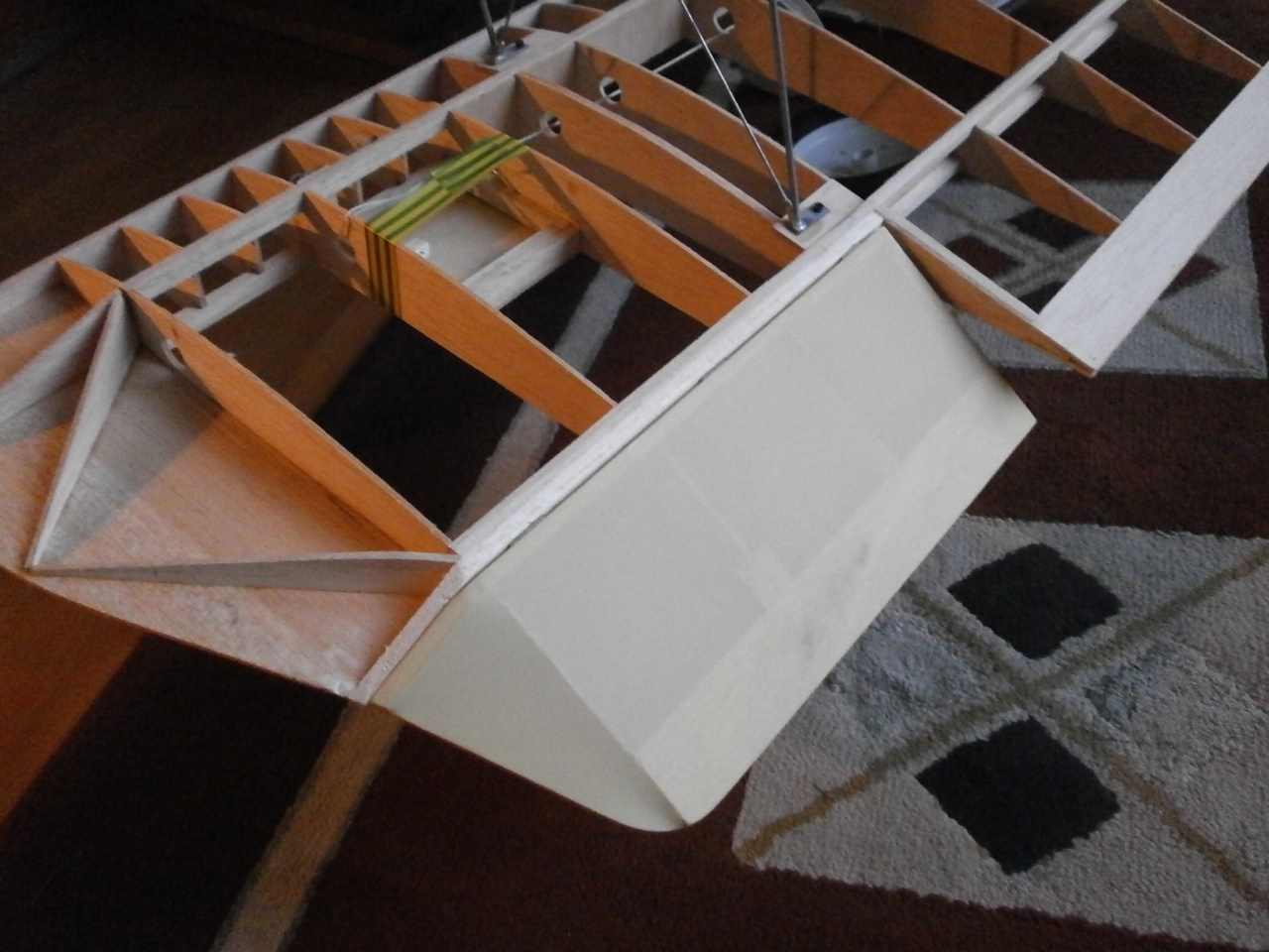
Again the wing is covered using exactly the same methods explained as the stabiliser. The only thing different here is, there are a number of small areas that need to be covered before the main covering is placed on. The two pictures below show the open section of the centre section being covered. Note that the tex has been carried over to the rib edges (pic two), this will allow for the top and bottom covering to finish at these points without the need to overlap which leaves unsightly seams.
|
|
 |
The next four pictures again showing the centre section trailing edge and ailerons covered in the same manner and again note the overlap onto the rib edges.
 |
 |
 |
 |
Once these areas are covered, I apply more
cover grip to the overlap of these parts ready to receive the top and bottom
covering.
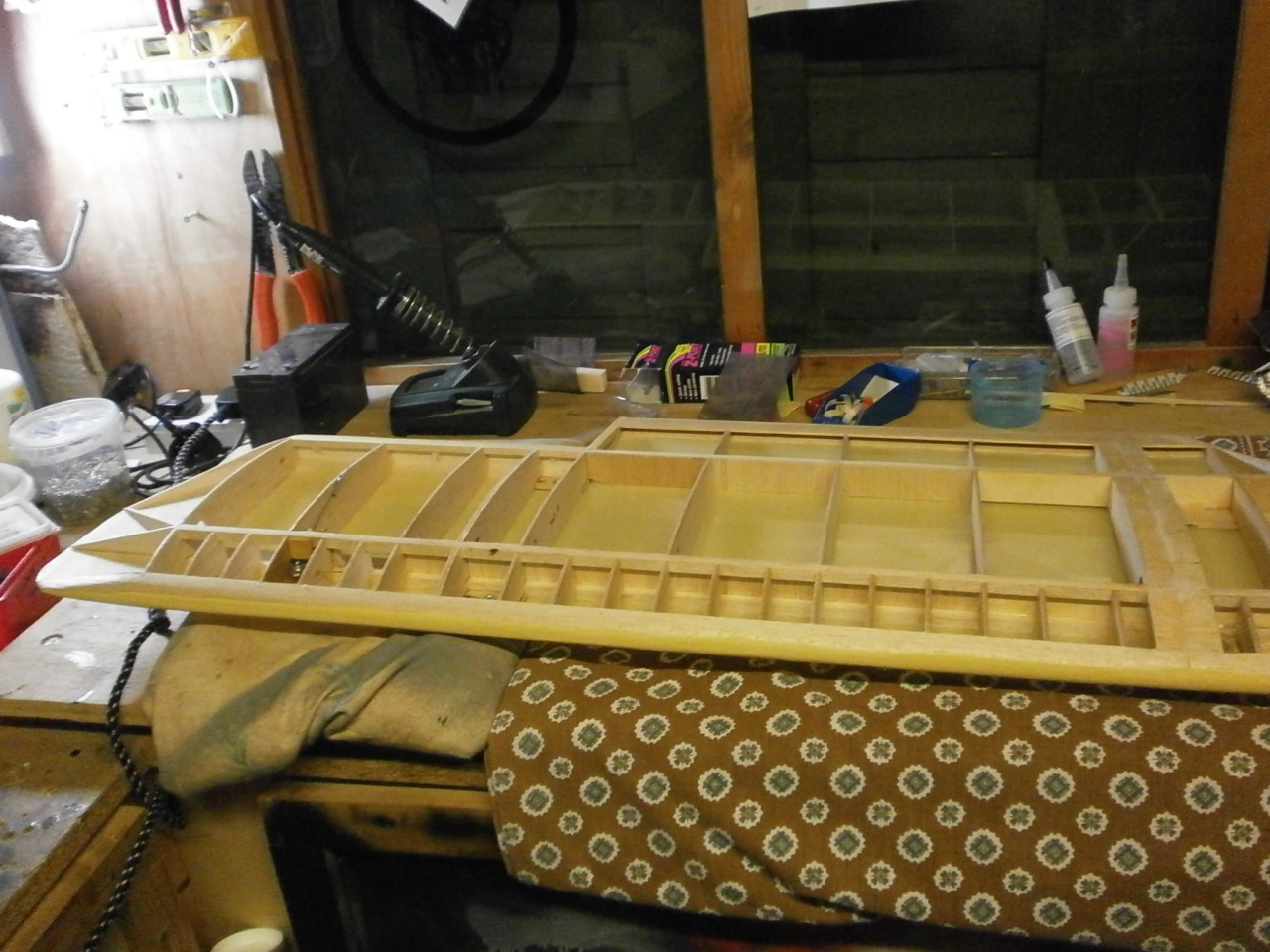
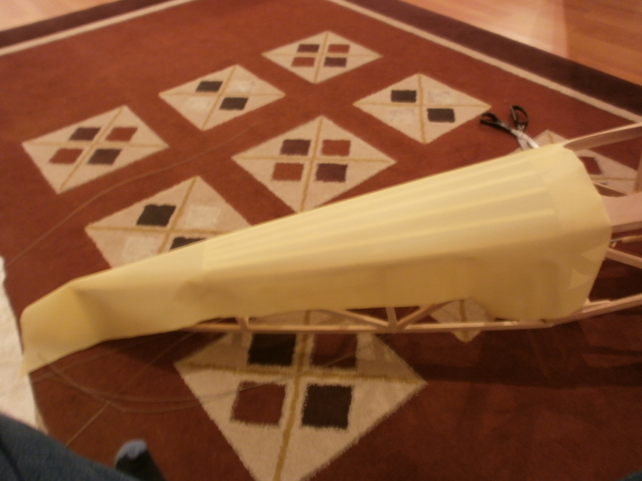
Now comes the fun part, covering the vast expanse of wing. I was going to cover
the wing in sections left, right and middle using three pieces of tex, but in
the end decided to cover the bottom section using one piece. Using just one
length on a wing this size requires a little forethought as if tackled without
it will lead to creases and a lot of frustration and more importantly the
potential waste of costly covering material.
First of all I laid out the covering over the
underside of the wing. Once happy with its alignment I started at one end
of the wing and tacked the covering into place as we did for the stabilizer
working in a diagonal manner tacking each side all the way to the over end of
the wing.
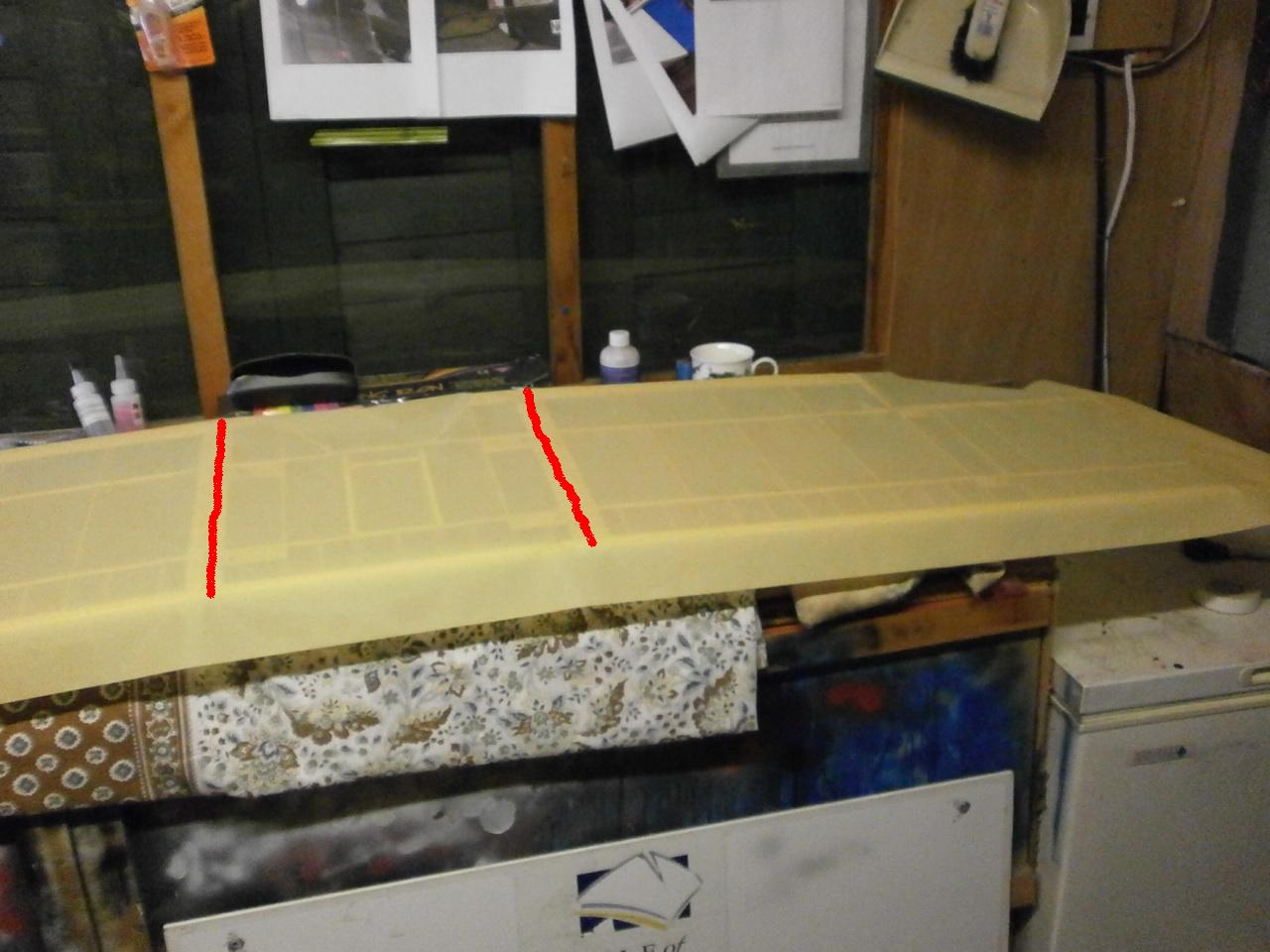
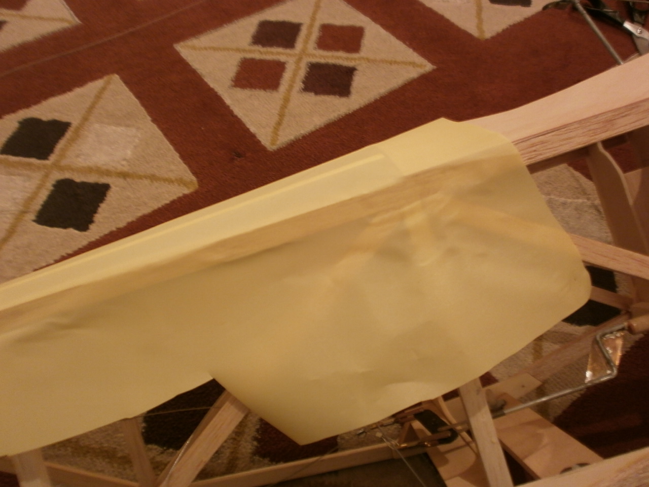
Next with the iron still set at 100 degrees, run the iron across the cord at
either end of the centre section see pic 2 below
Once this had been carried out, the centre section was (on the same heat) stretched as we had done with the stabilizer. Next the left side of the wing was sealed down into place and then the right both using the same method as described in the stabilizer.
 |
 |
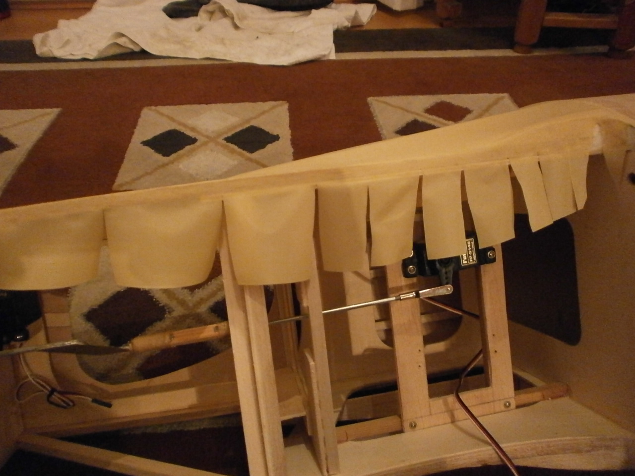
The edges where then sealed down as previously described see pics below.
 |
 |
And the again starting with the centre
section and then left and right panels, the heat is turned up to 350 degrees and
the covering is shrunk to its final tension.
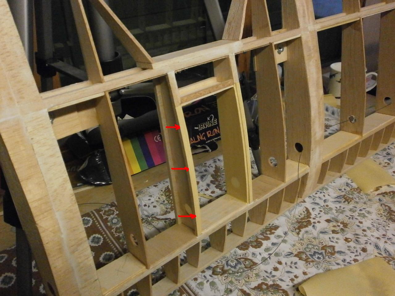
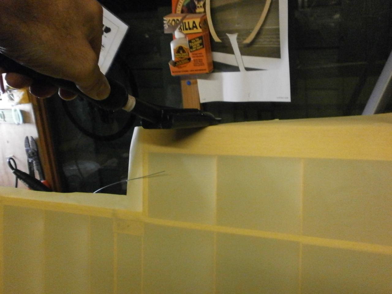
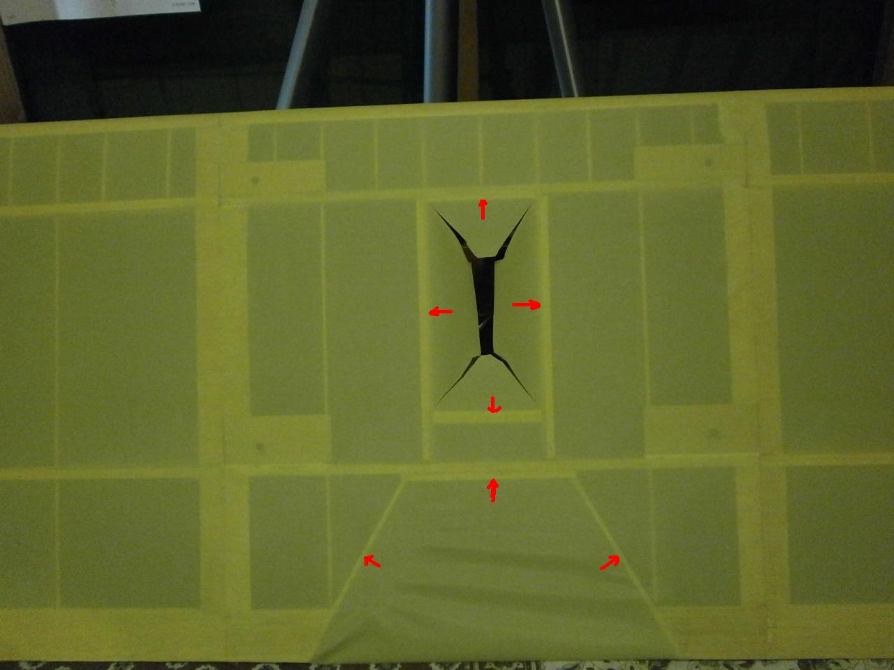
The first picture below shows arrows indicating where the tex is cut flush with
the edges of the ribs and trailing edges eliminating the need for any overlap as
explained earlier leaving a nice neat invisible finish.
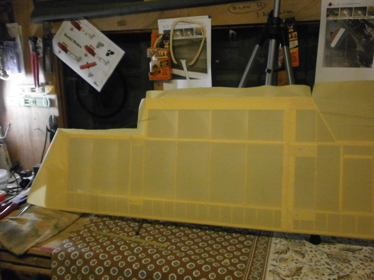
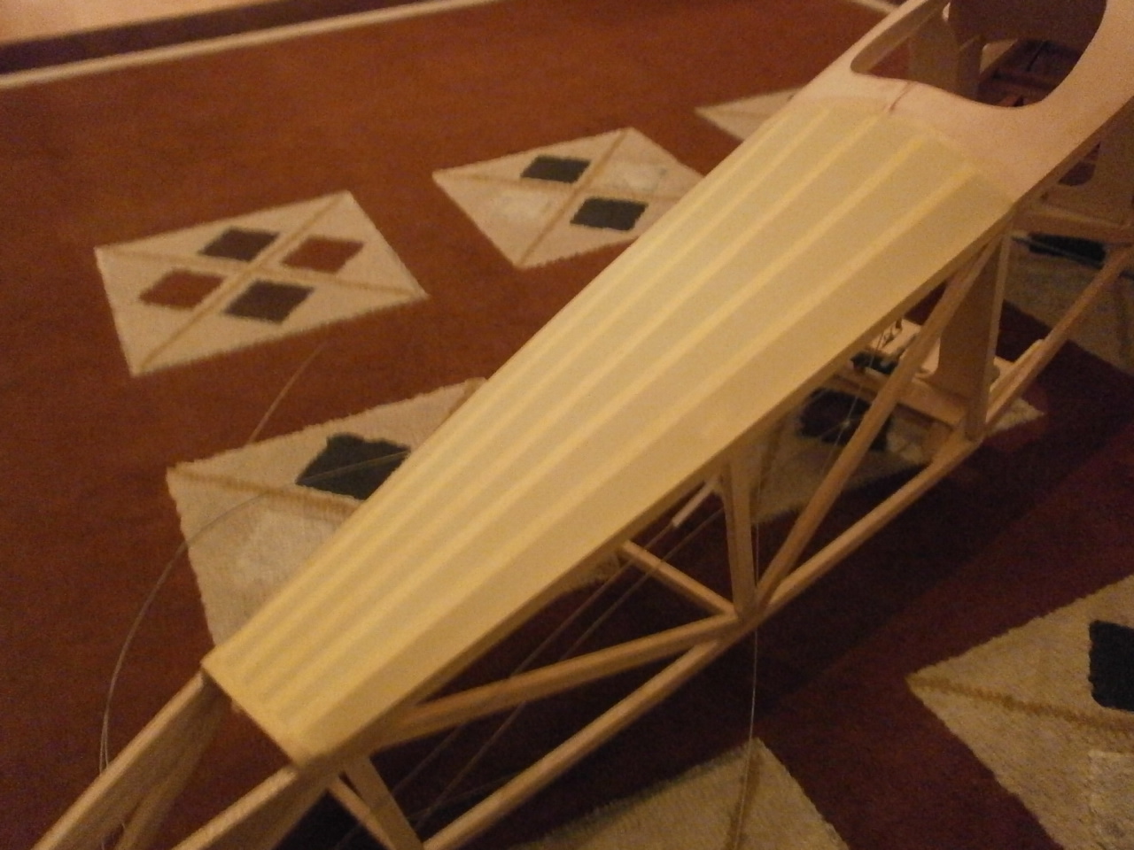
The second pic showing the now trimmed and completed bottom section of the wing.
 |
 |
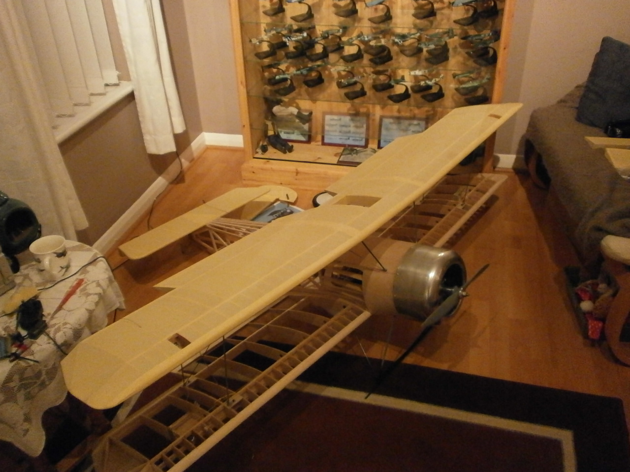
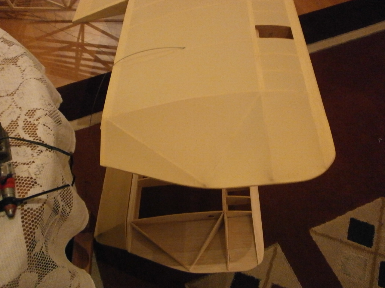
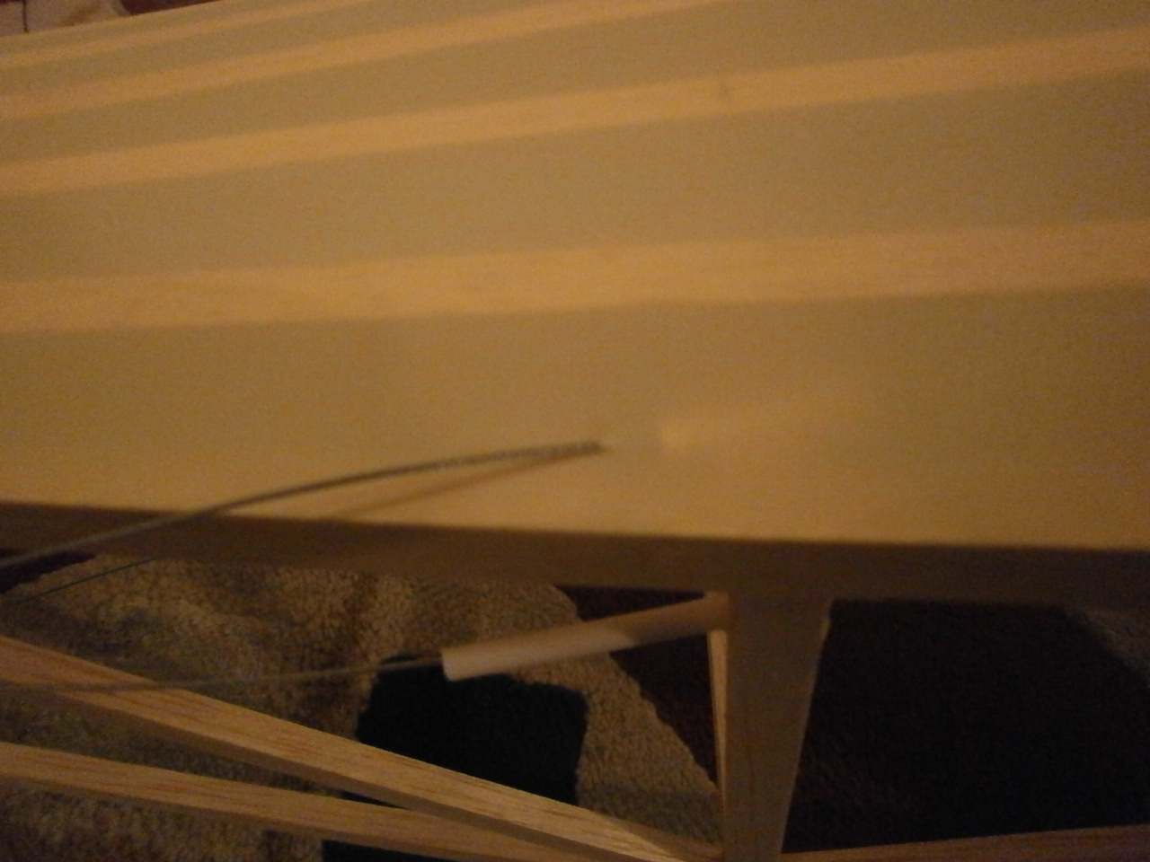
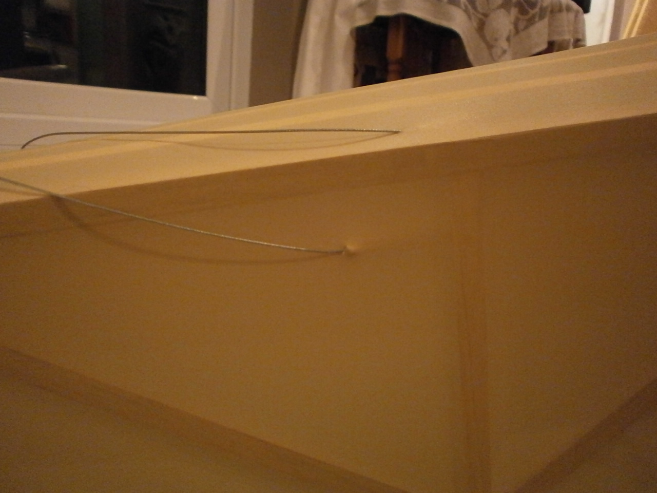
The next two pics showing the wing sitting in place now fully covered, sitting on the struts and also the wing tip, note no wrinkles.
|
|
 |
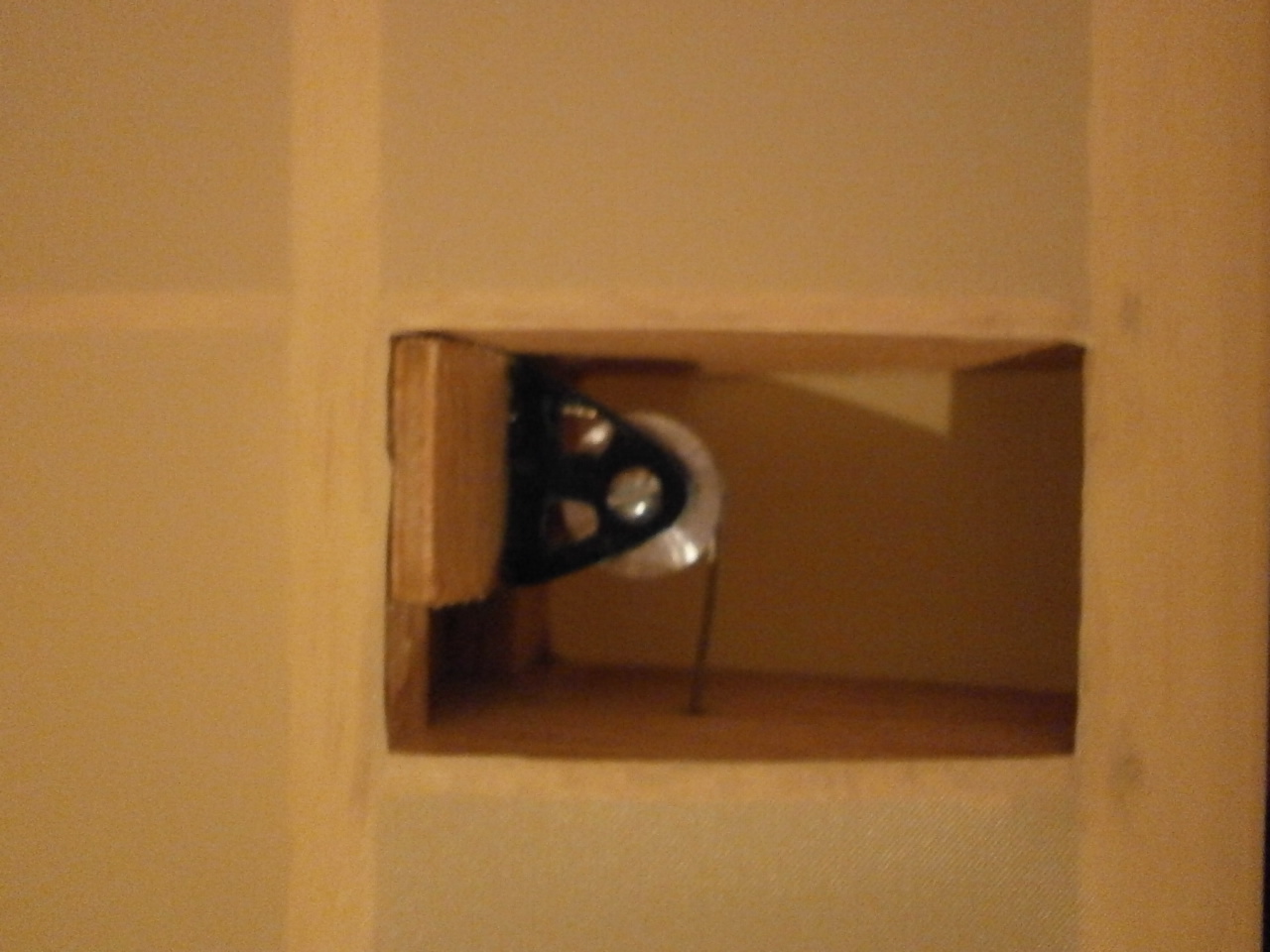
On the full size aircraft both top and lower wings, on some models of the pup had viewing windows showing the pulley's that worked the ailerons. Below are a couple of pictures showing my attempt to replicate this. The pulley's and their mounts have been made from scratch with the use of a modelling lathe for the pulley's and the mount brackets have been cut form aluminium and hand crafted.
The second pic shows the aileron cables exiting the wing operated by the pulley's.
 |
 |
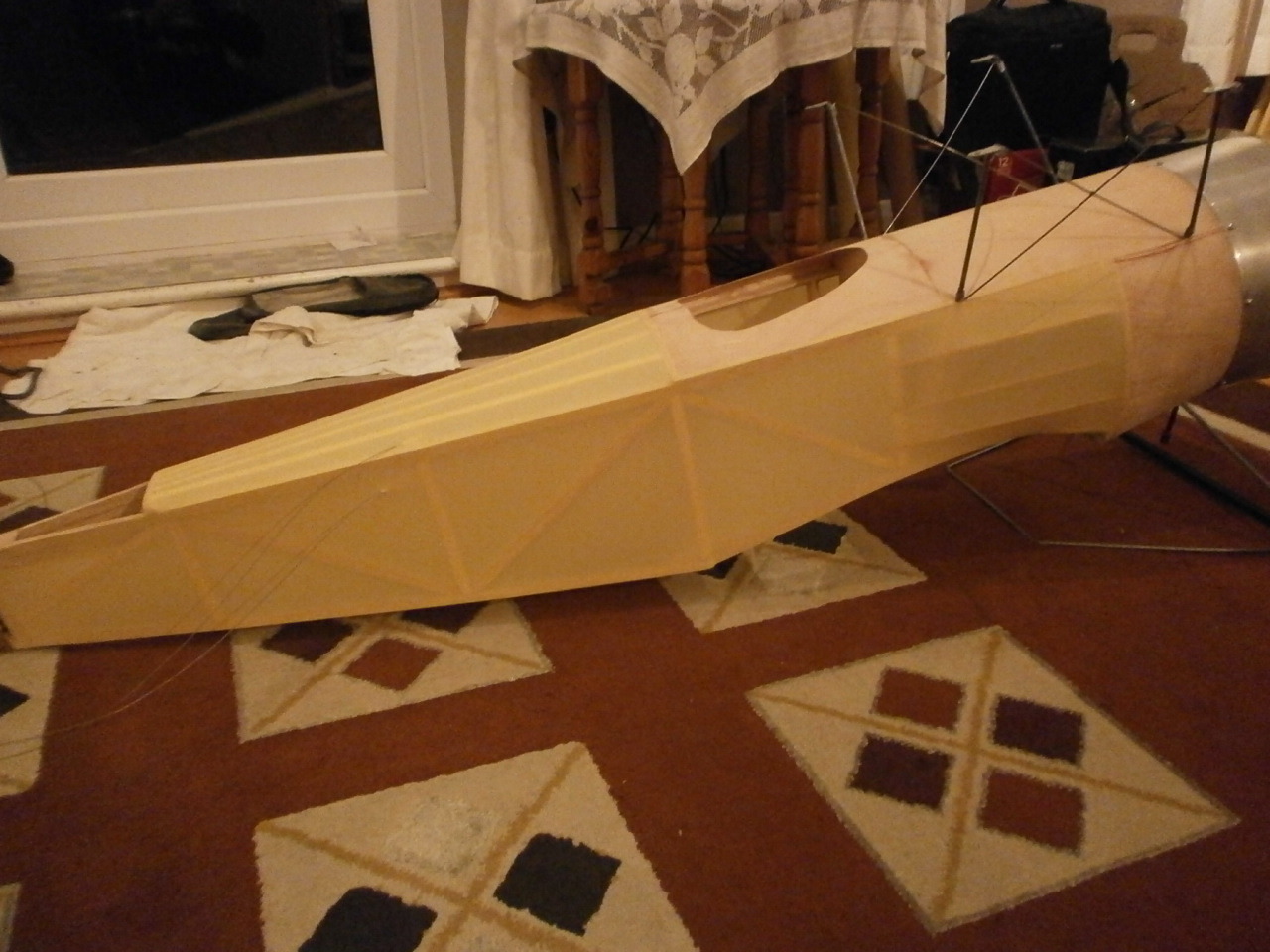
Fuselage covering
The fuselage is covered pretty much the the same way as the rest of the model. The following pictures show the sequence that was used.
First the top decking is covered.
 |
 |
Note: In the second picture below the overlap is not continued right over the former but trimmed back revealing the balsa. This is because the stabiliser when positioned will need to be glued to this former.
 |
 |
 |
 |
The first picture showing the closed loop wire now exiting the fuselage through the covering. There will be a strengthening patch place around this area just like the full size.
 |
 |
First picture showing covering cut, so allowing it to be contoured around the wing saddle.
 |
 |
Pictures below showing the now completed top and sides. Note that the top forward and side ply sheeting has not been covered. this will be sheeted with aluminium as per the full size. I will cover the processes of applying this material further on in the build (Adding aluminium panels)
 |
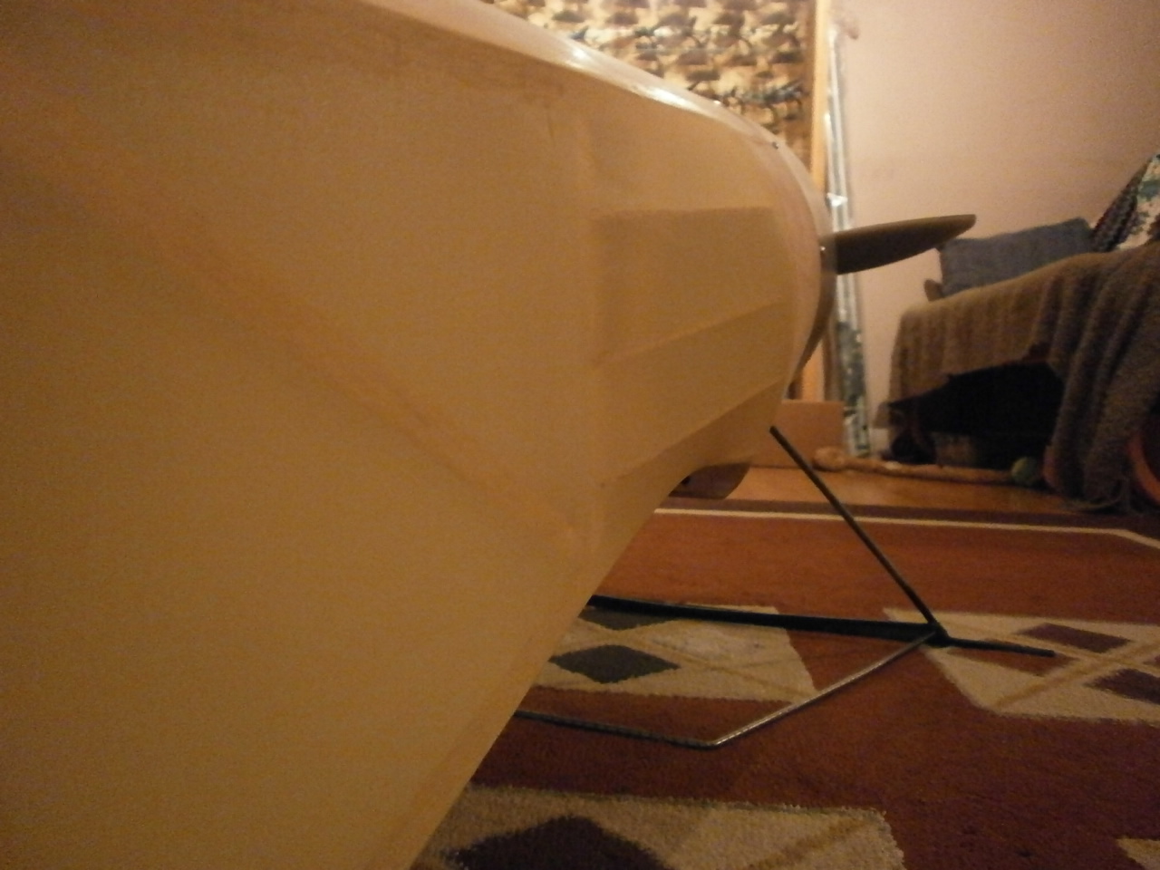 |
The underside of the fuselage has not been covered as there is still a need for access.
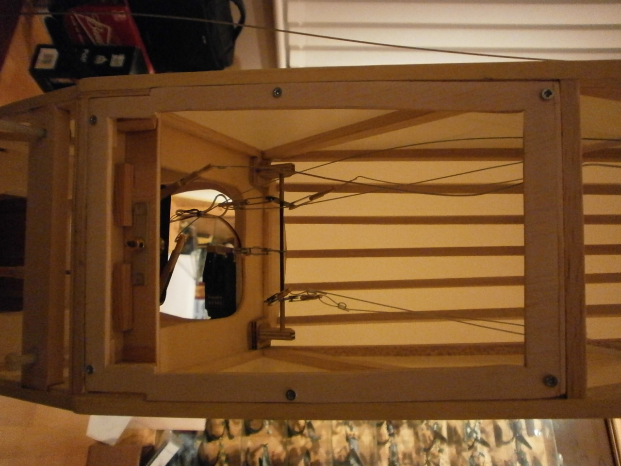
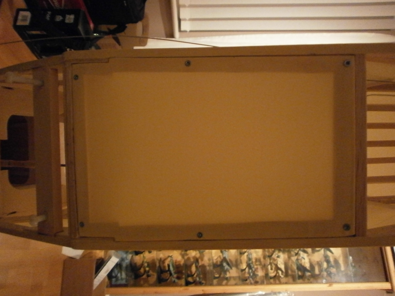
The first thing I wanted to do with the underside of the fuselage was to make an access panel that will allow for easy access to the closed loop control connections. This item was made from light ply and is help in place by six screws see picture below. 0nce made the panel is covered and then secured into place.
 |
 |
Now the access panel is covered I wanted to concentrate on the stitching that runs along the fuselage. Having looked around at other model sites to see how other people are tackling this. I decided that I would go my own way.
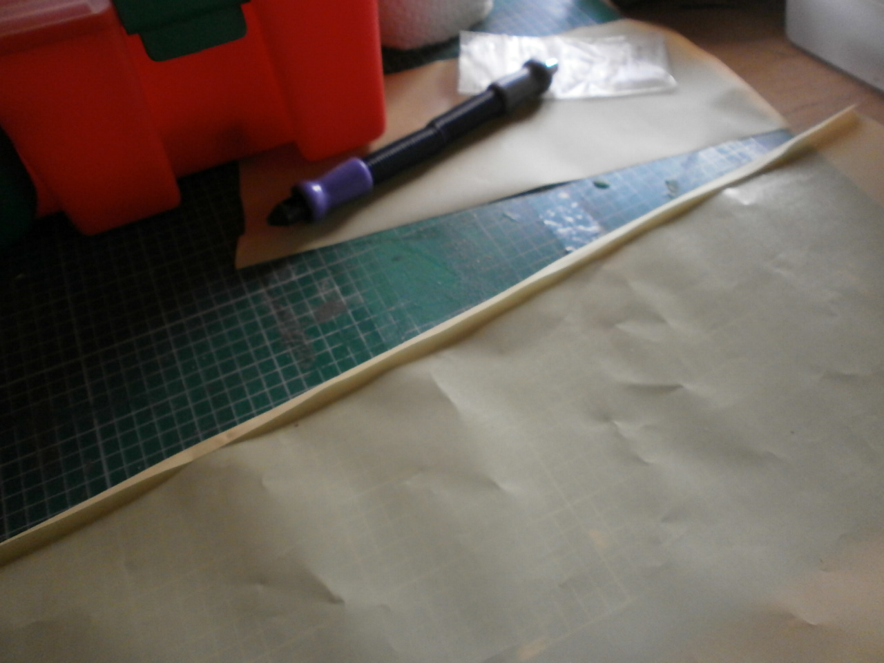
First I took a length of solatex and folded
it in on itself just a little wider than the eyelets I'll be using to past the
stitching through.
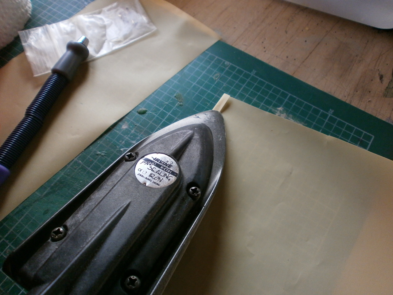
Once folded it is sealed to itself using the heat iron set on a low heat see
pictures below
 |
 |
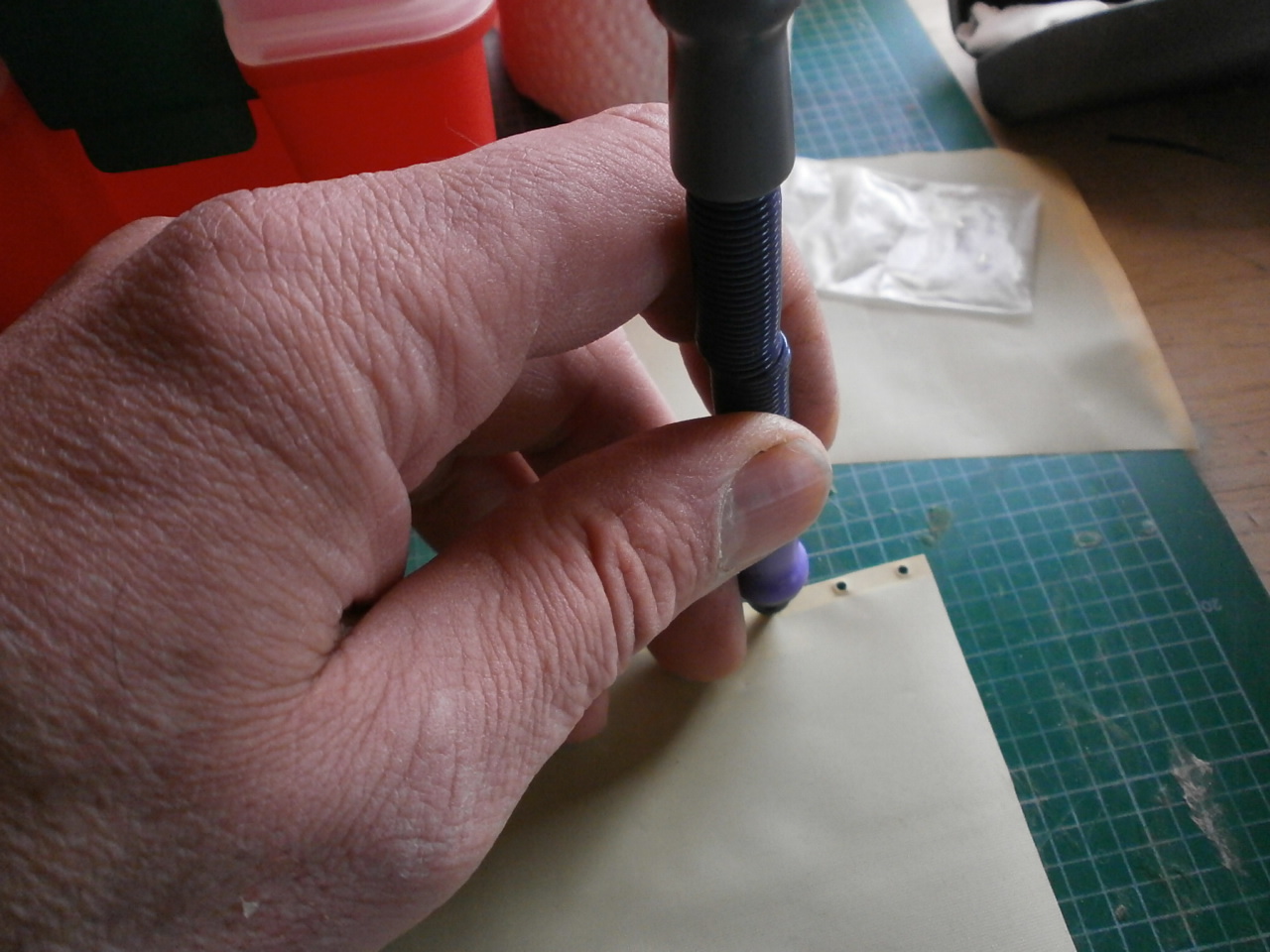
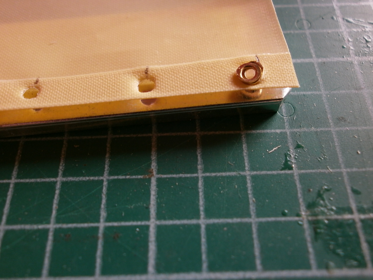
Once sealed the next job is to mark out the locations of the holes (approximately 12mm for this scale)
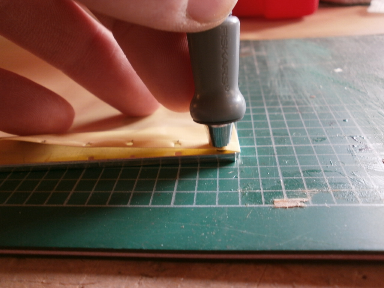
Once marked with the eyelet/ hole punch tool holes are punched out at their required locations. See first picture below.
Next the brass eyelets are located into place (these can be purchased from Mick Reeves Models) Picture 2 below
 |
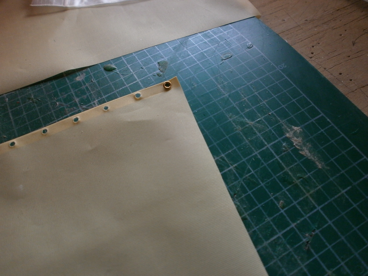 |
Once in situ the eyelets are burred over creating a lip hence stopping them coming back out. This job takes time and is somewhat laborious, but I'm sure when you see the final results make it all worth it
 |
 |
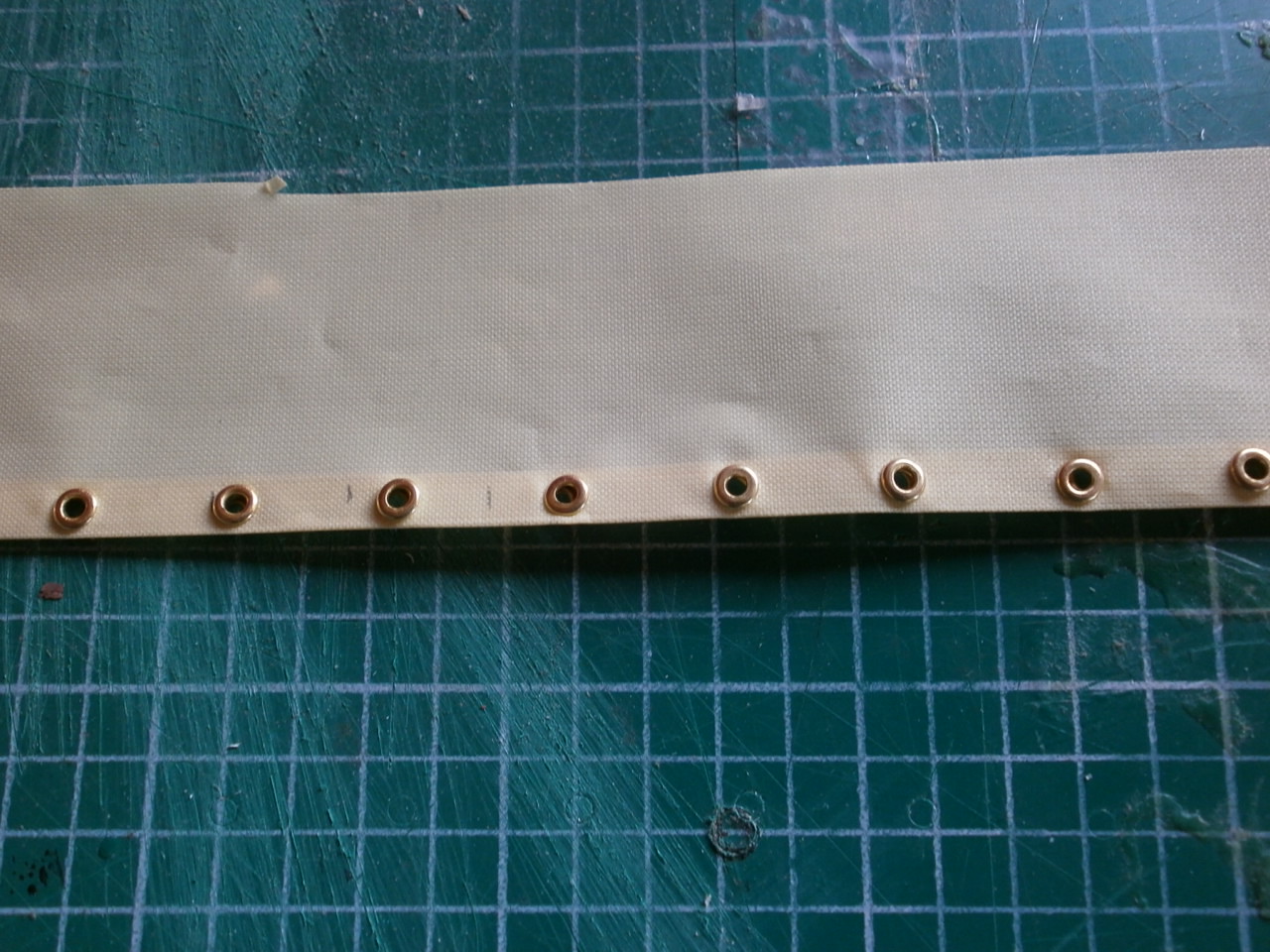
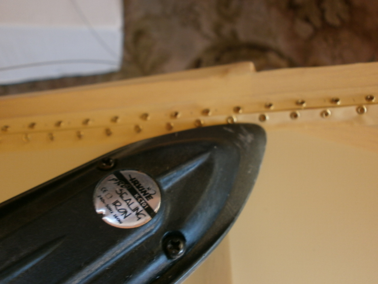
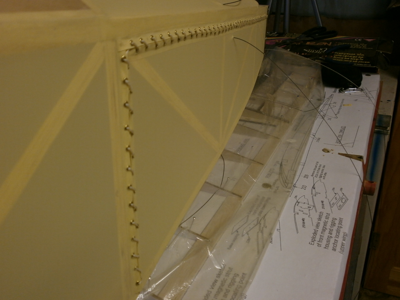
With all the eyelets now in place and secure the strip is cut down to size just leaving enough unfolded soletex to enable me to heat shrink it into place. Once this is done the strips are located into their scale positions and heated into place. See pictures below.
 |
 |
 |
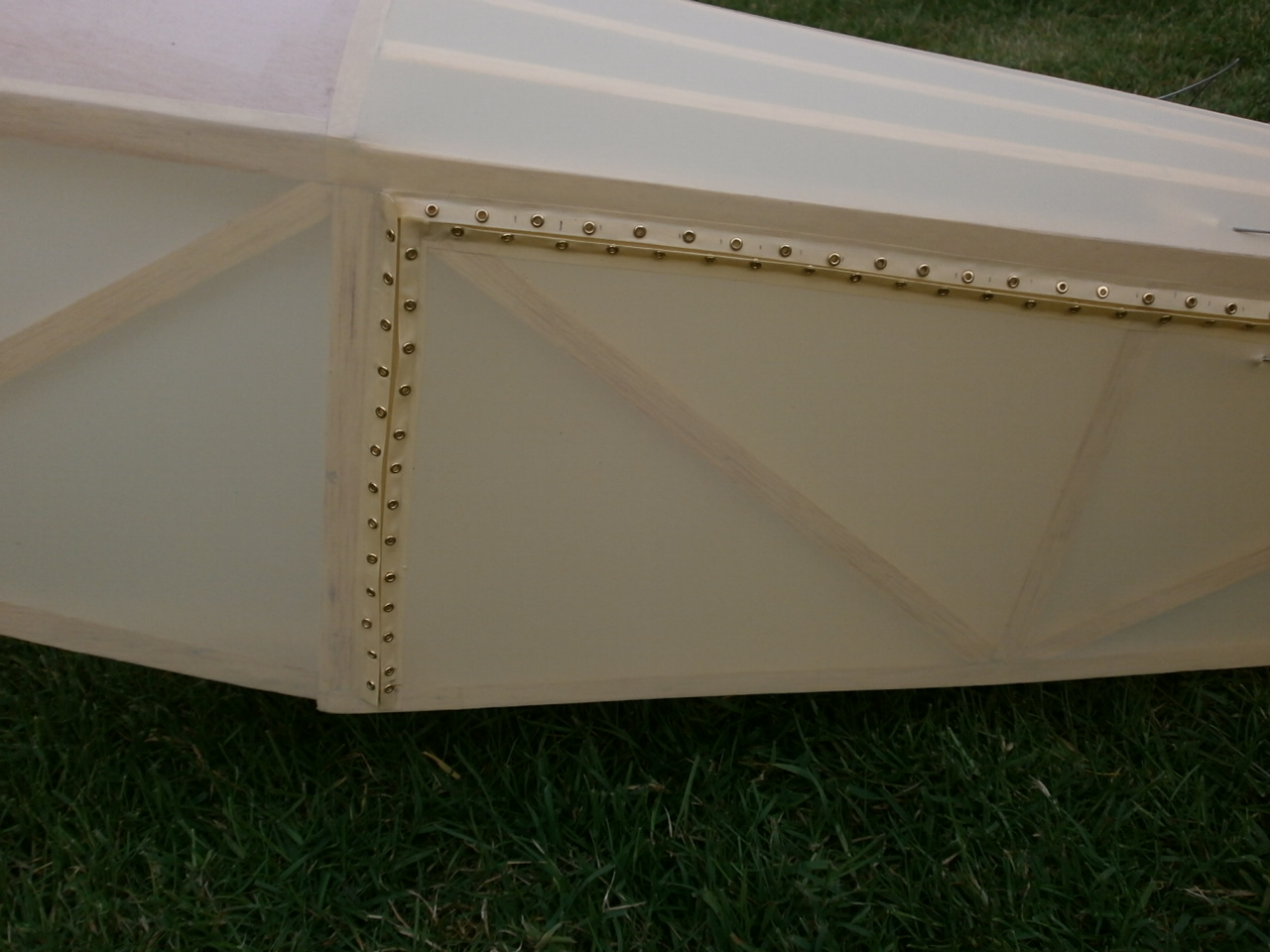 |
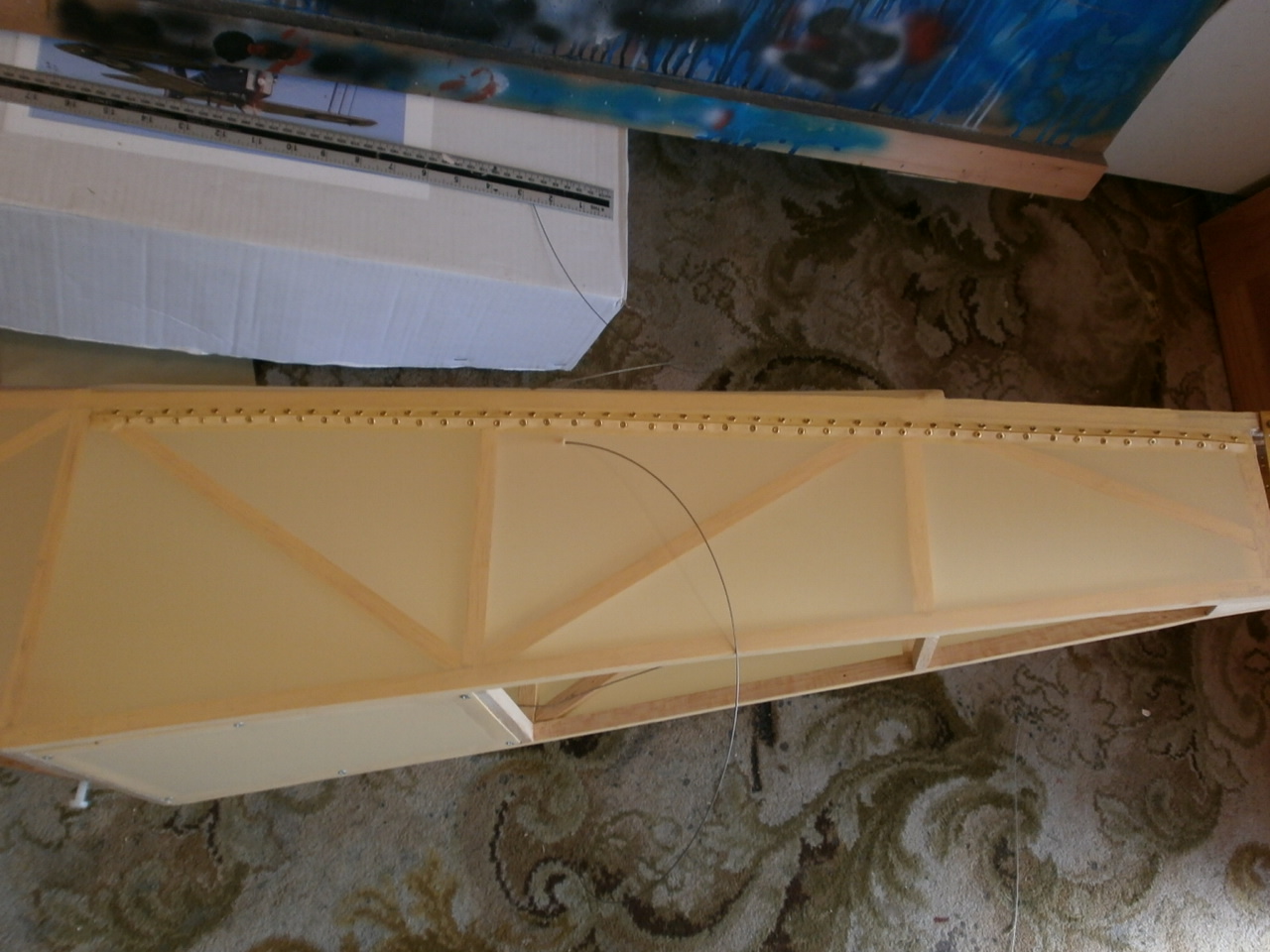
With the eyelet tapes now in place we are able to add the stitching and below are pictures of the final result. I hope you will agree that although this is a some what timely procedure (about three hours per side) it is well worth the effort as this is a major feature of the plane.
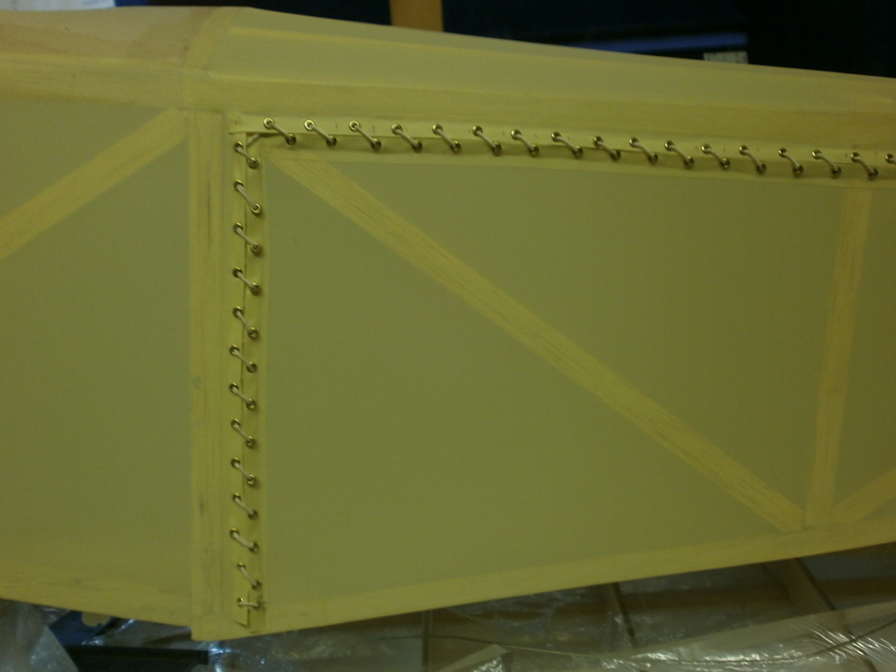 |
 |
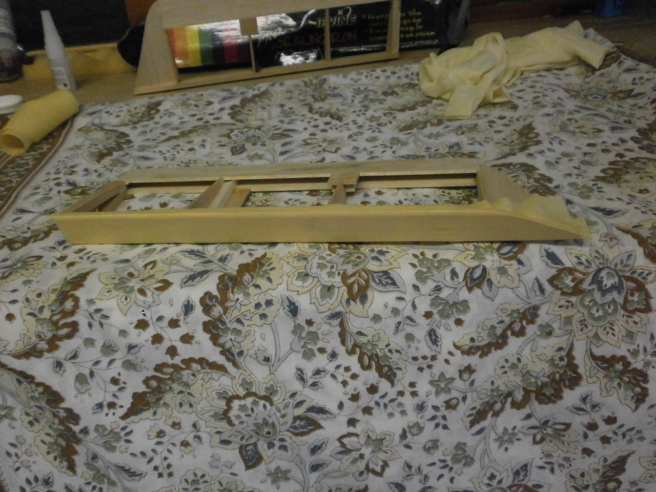
Construction of Stabiliser
Construction of Rudder and Fin
Fuselage page
Struts &
Control Linkages
Construction of Wing
Aileron installation
Engine installation
Final Construction
Rib Tapes