Wing Construction
Having completed both the stabiliser and rudder sections, I can now start on the wings.
|
|
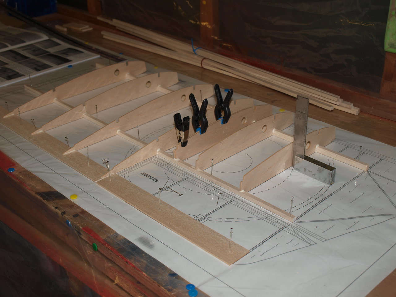
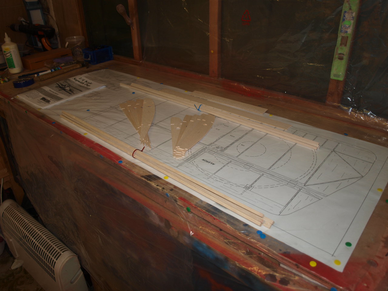
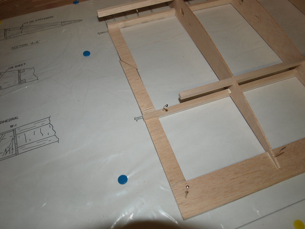
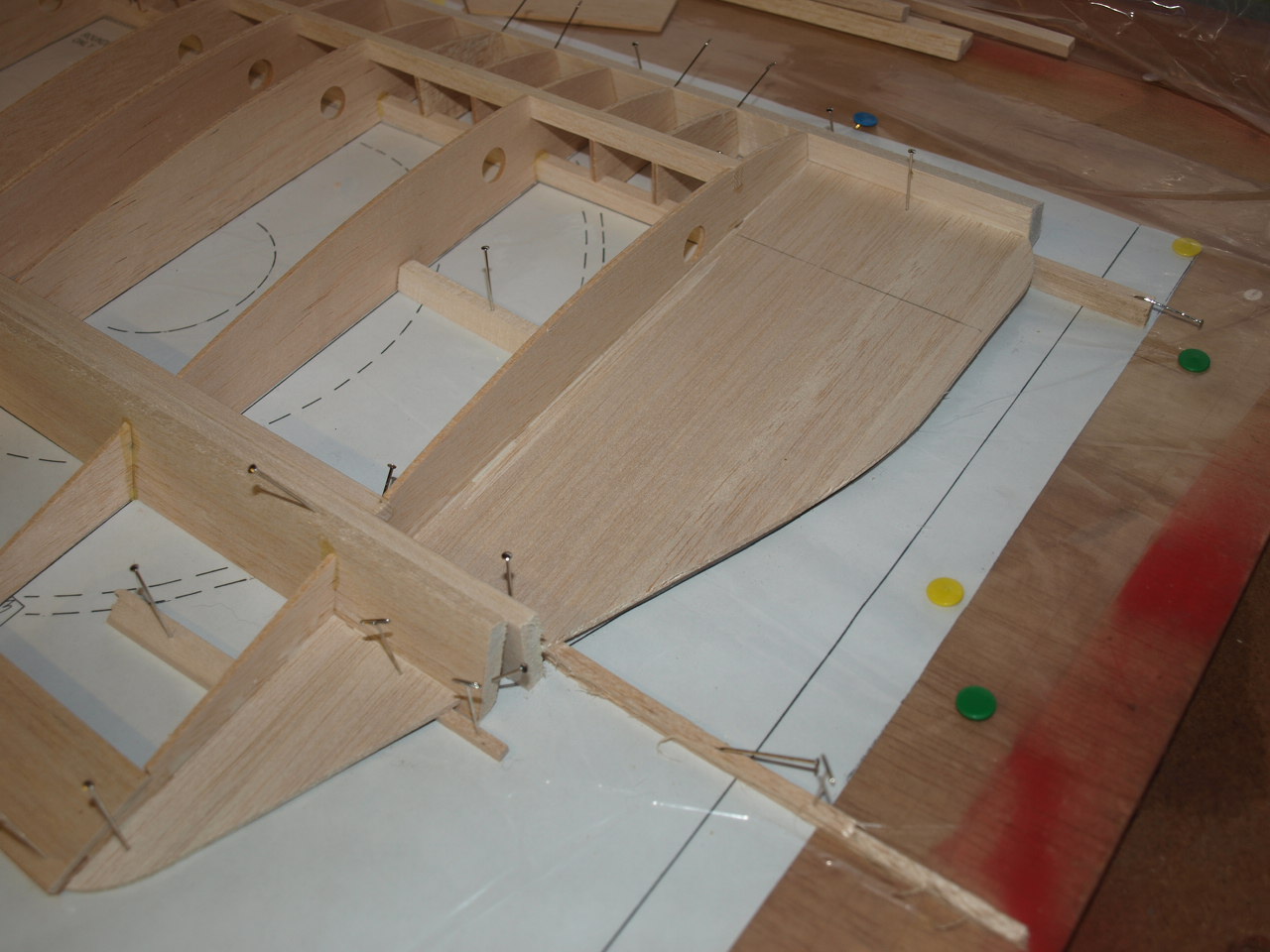
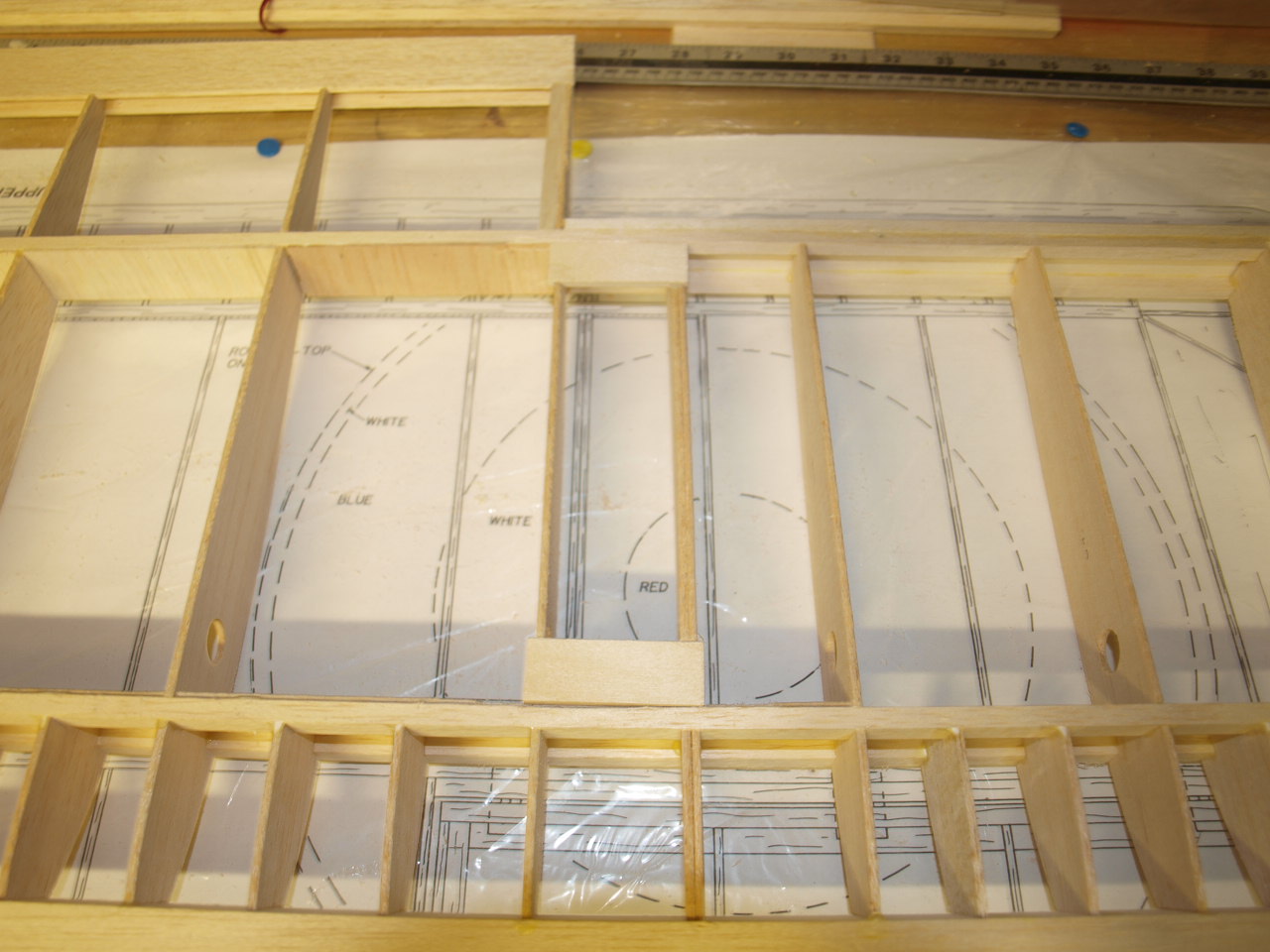
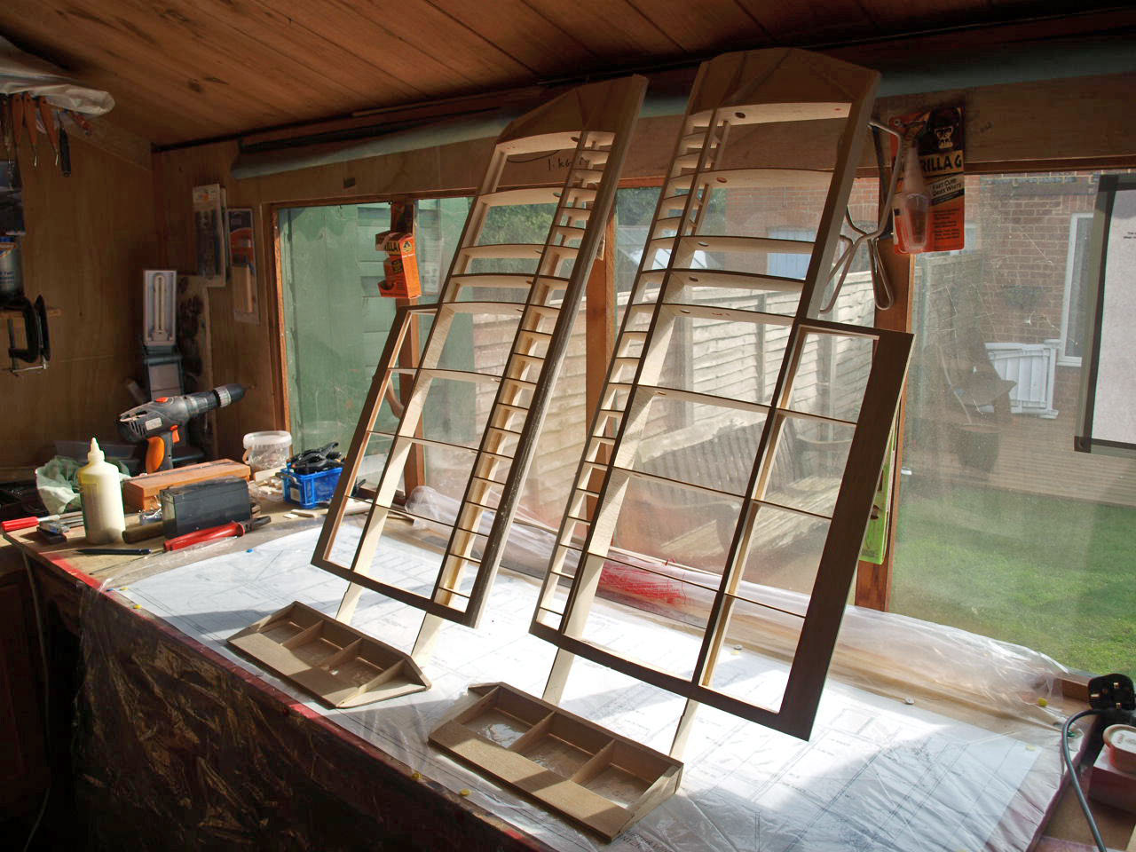
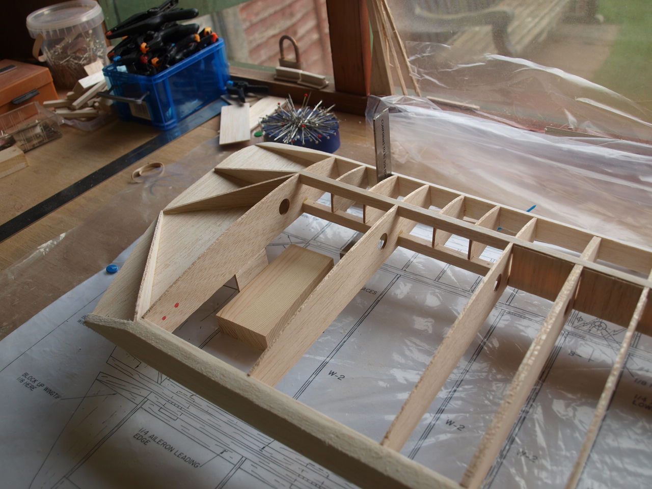
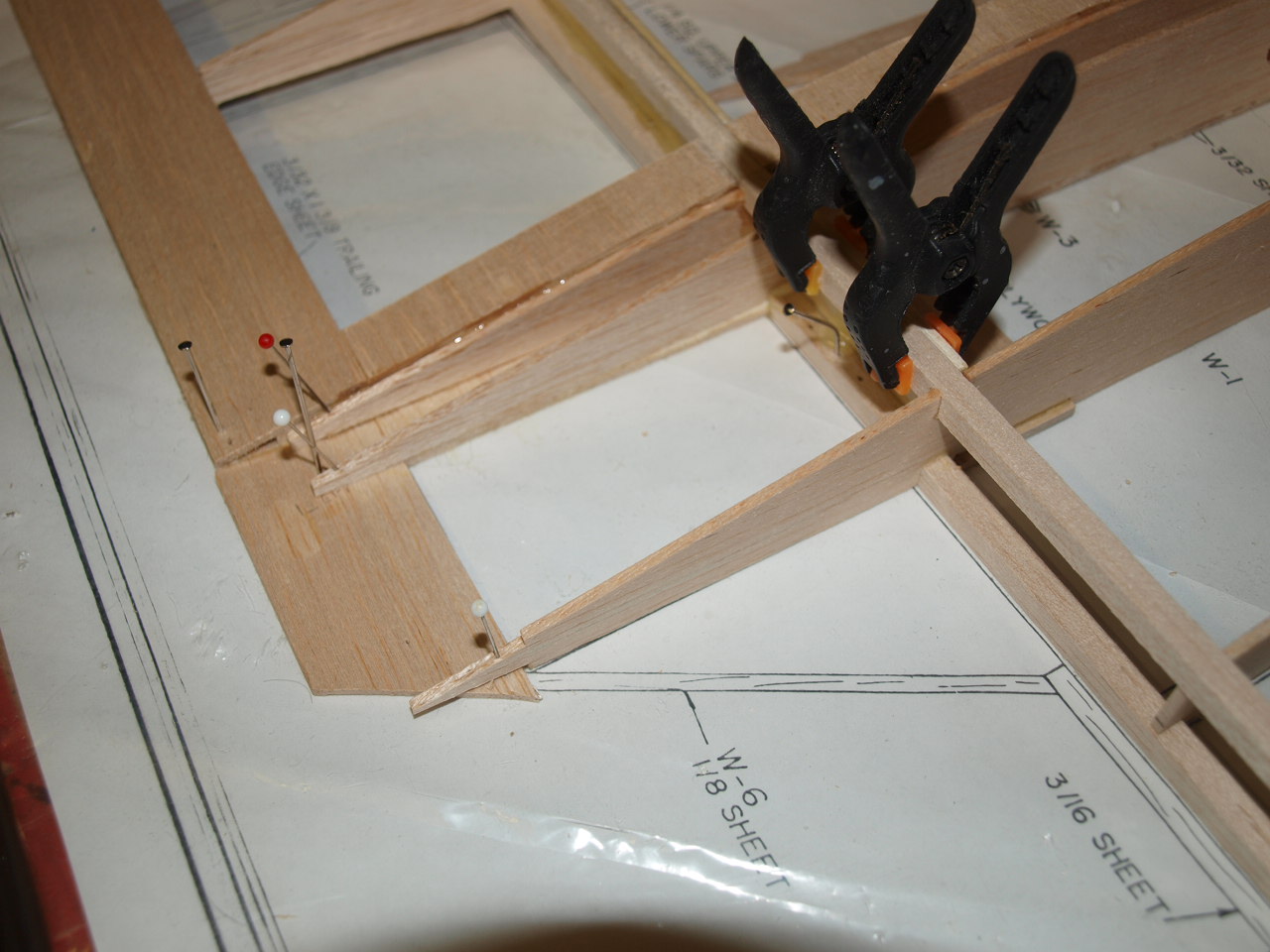
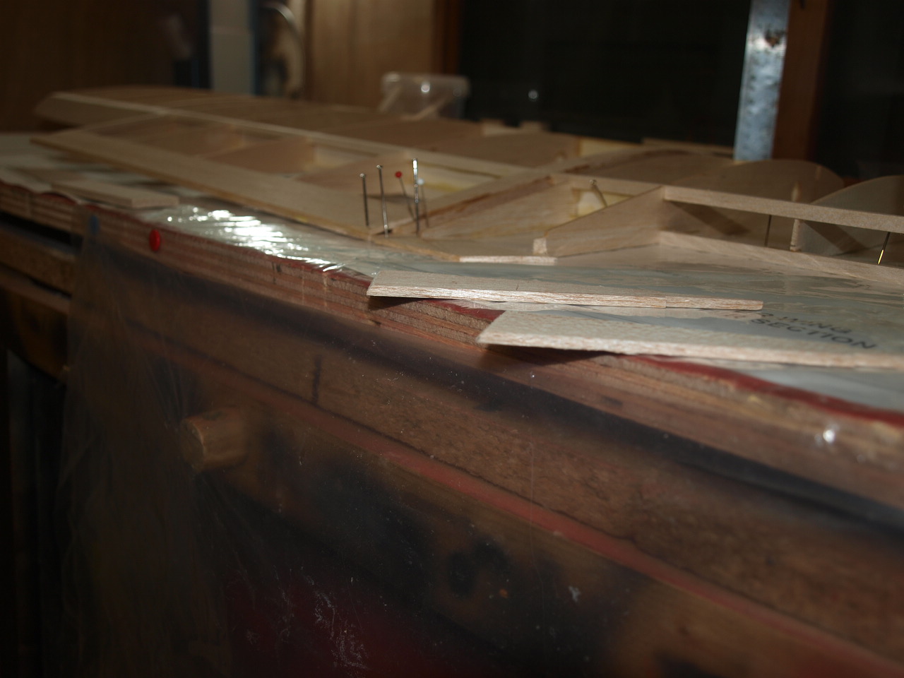
The picture above shows the right top wing panel plan in place on the building board. This was part of a larger plan that contained both left and right and centre panels. This was to big to place on the building board so had to be carefully divided to ensure that each section was not damaged.
In the picture you will see the basic components needed to get me started e.g. 3/8 x 1/4 main spars, 1/4 x 1/4 rear spars, 3/32 x 1' 3/8 balsa sheet trailing edge, 4 W1 ribs and 5 W2 ribs two of which will need to be laminated together.
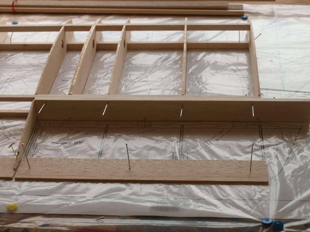
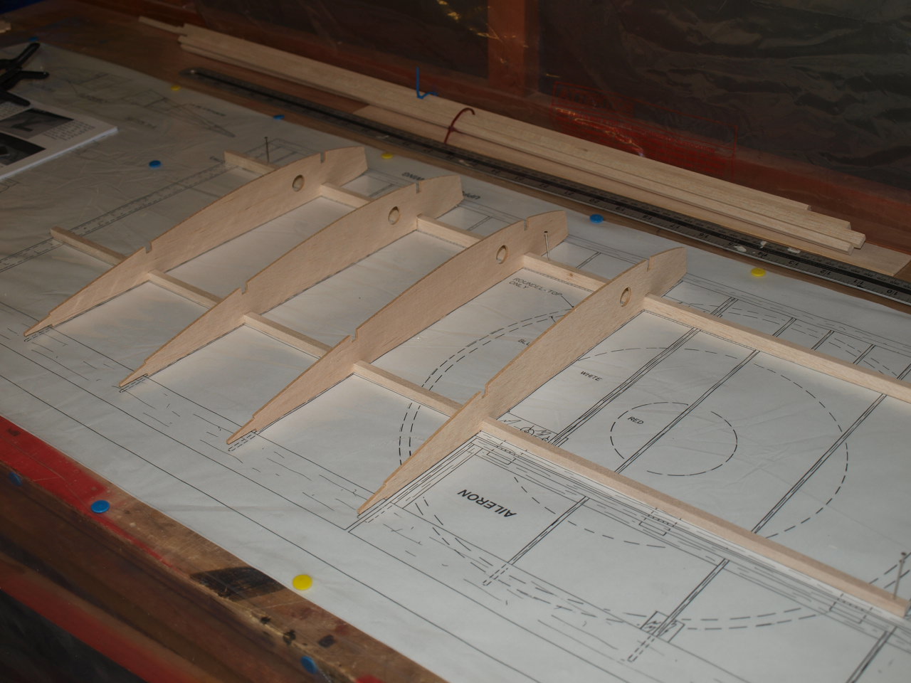
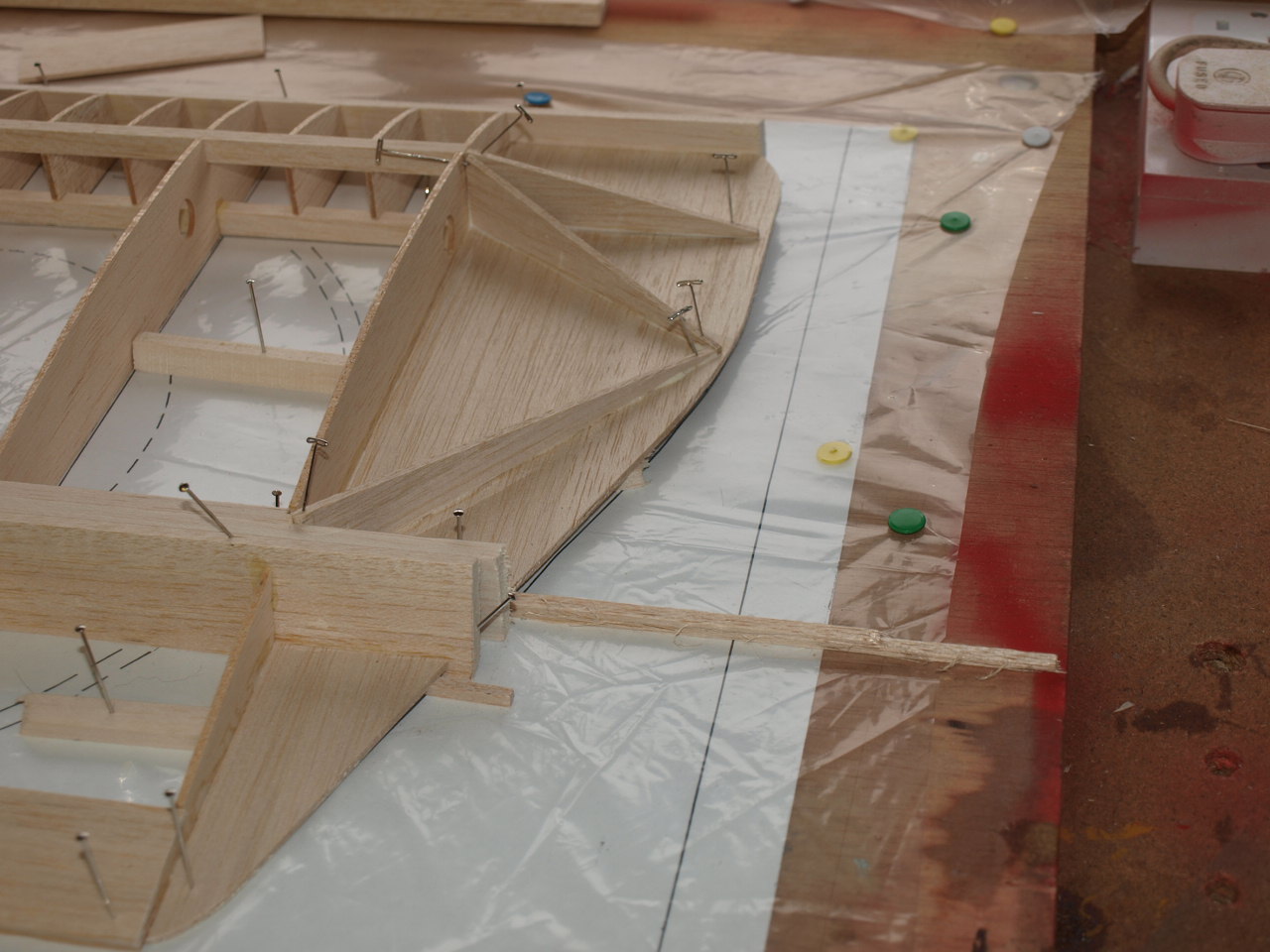
The lower main spar is pined into position over the plan and then the four W1 ribs are evenly spaced out on the plans allowing accurate position of the rear spar. Once this is in position it is also pined into place. (See pictures below)
 |
 |
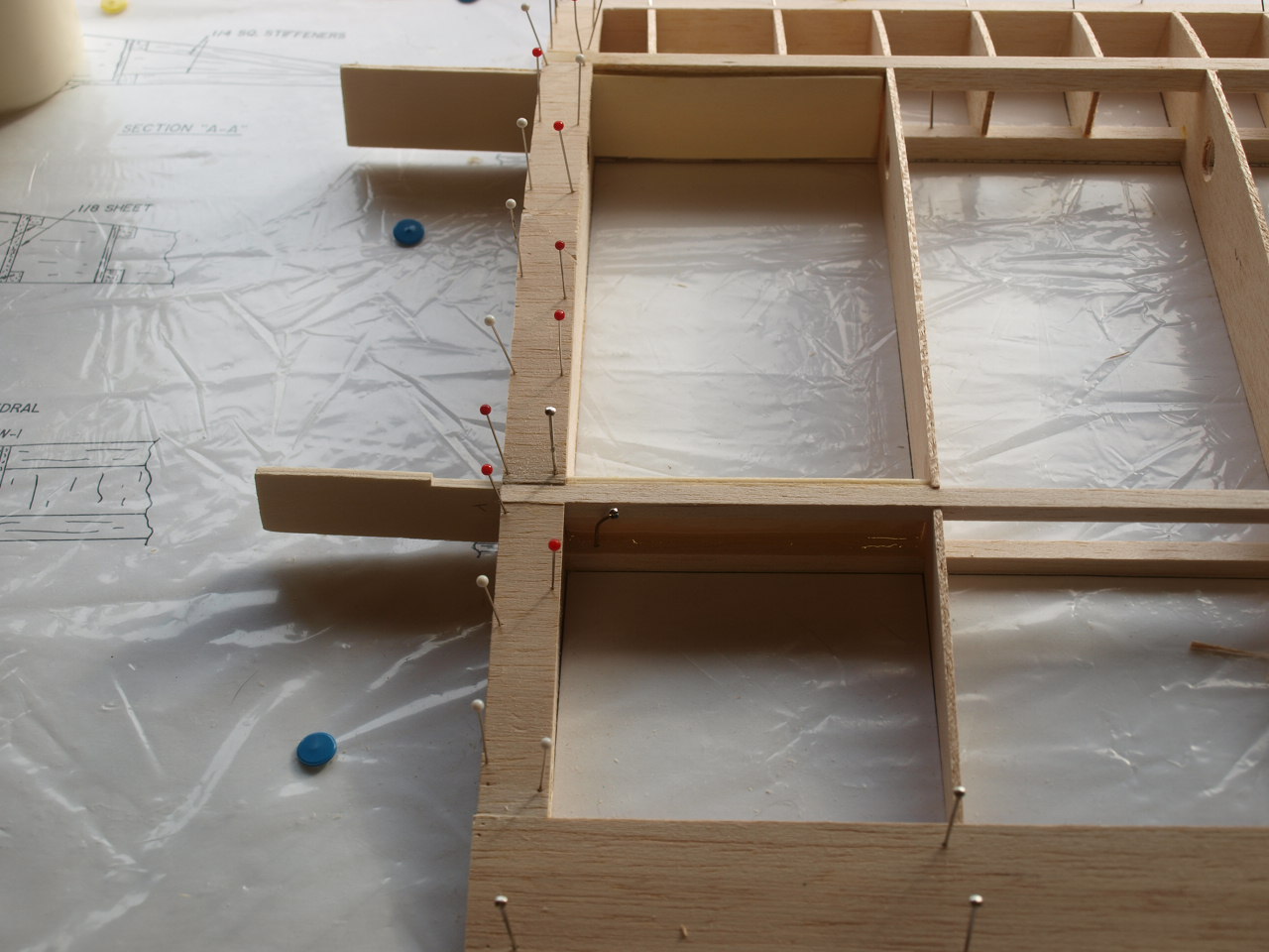
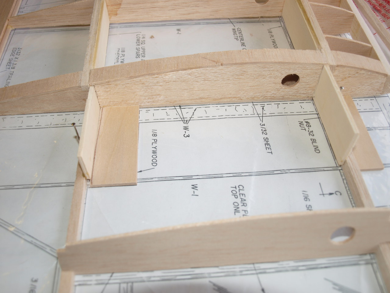
The lower portion of the trailing edge is next positioned along with the balsa strips that the W3 ribs will sit on at the root of the wing. The picture on the right shows W2 rib laminated.. This is because when it is in position it will be used to house a ply block and captive nut that secures the wing struts to the wing.
 |
 |
Once happy that everything fitted and was square, the the parts where glued into position
|
|
Wing construction Video part 1
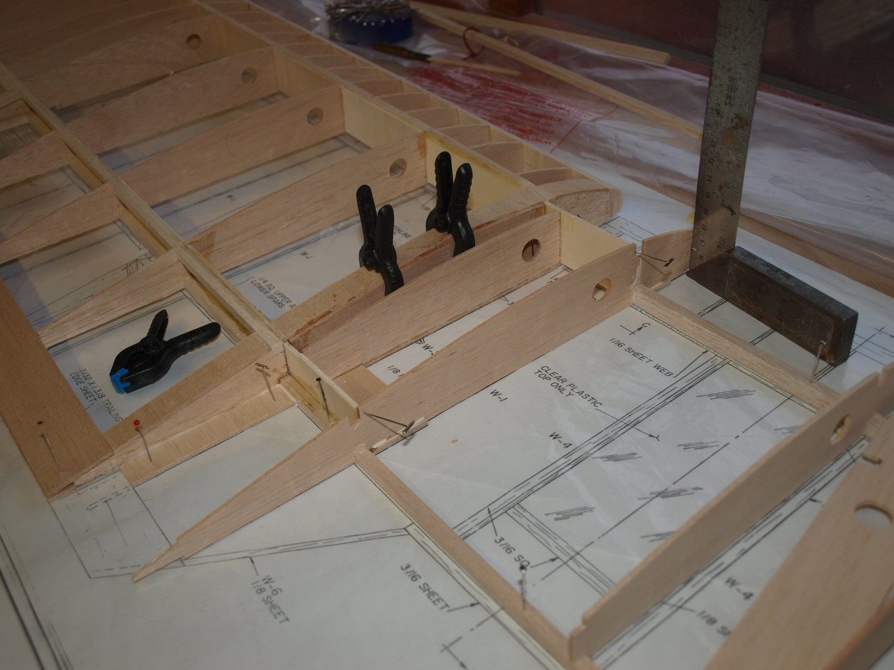
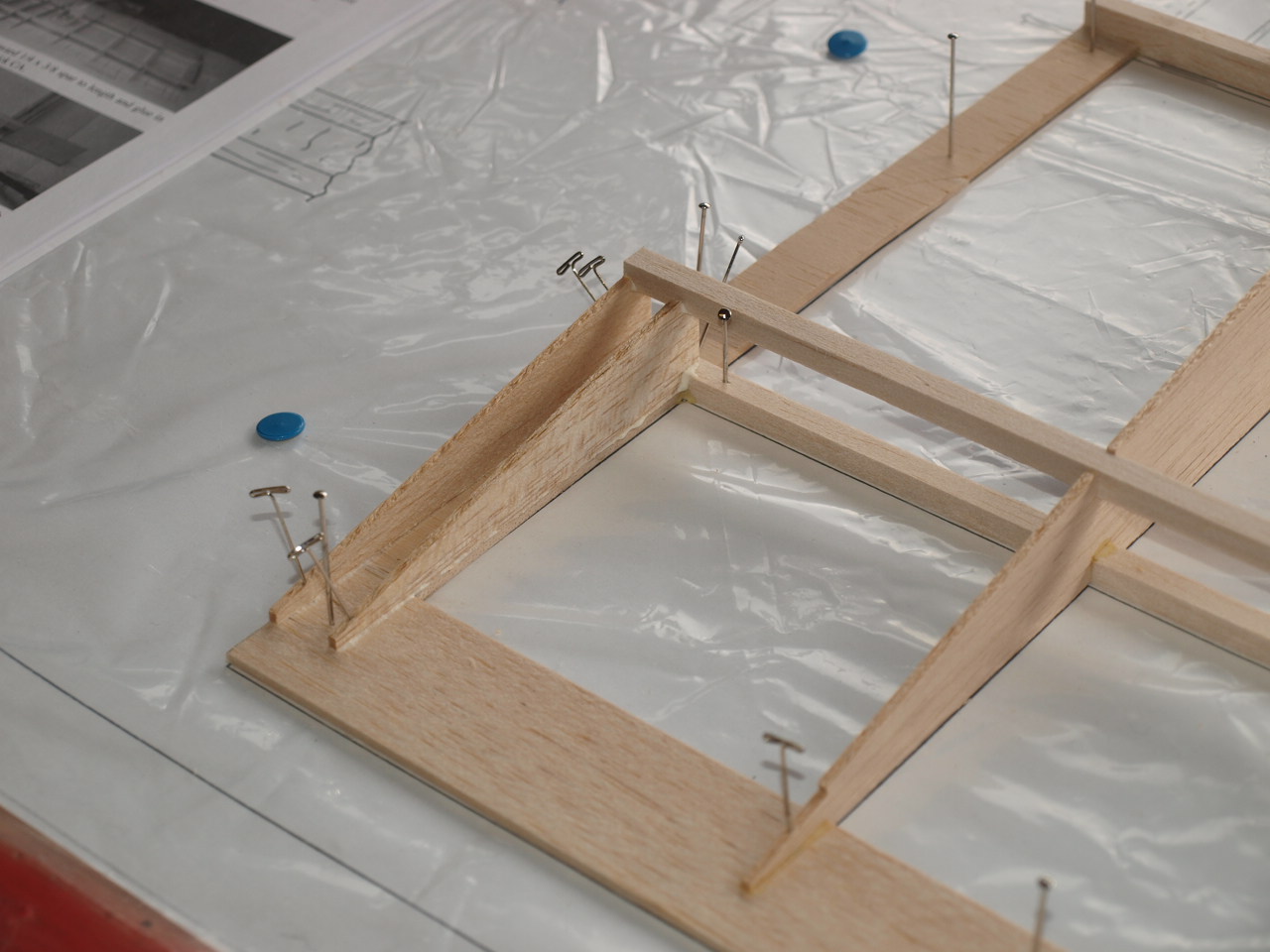
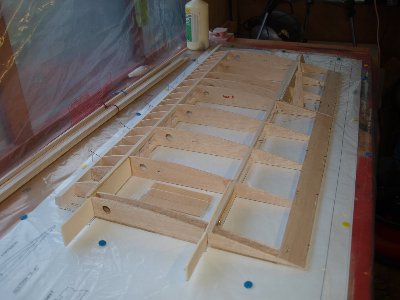
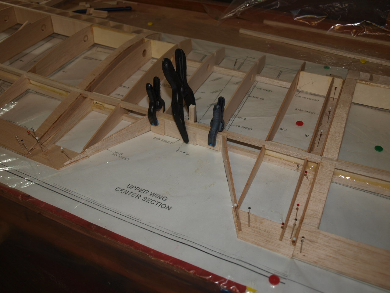
Once all had cured, I cut to length and glued into position the top front and rear spars. You will also see in the picture below, I have also added the aileron brace to the wing. This has been cut 1/4" longer that required to aid with the final shaping at the wing tip as per instructions.
|
|
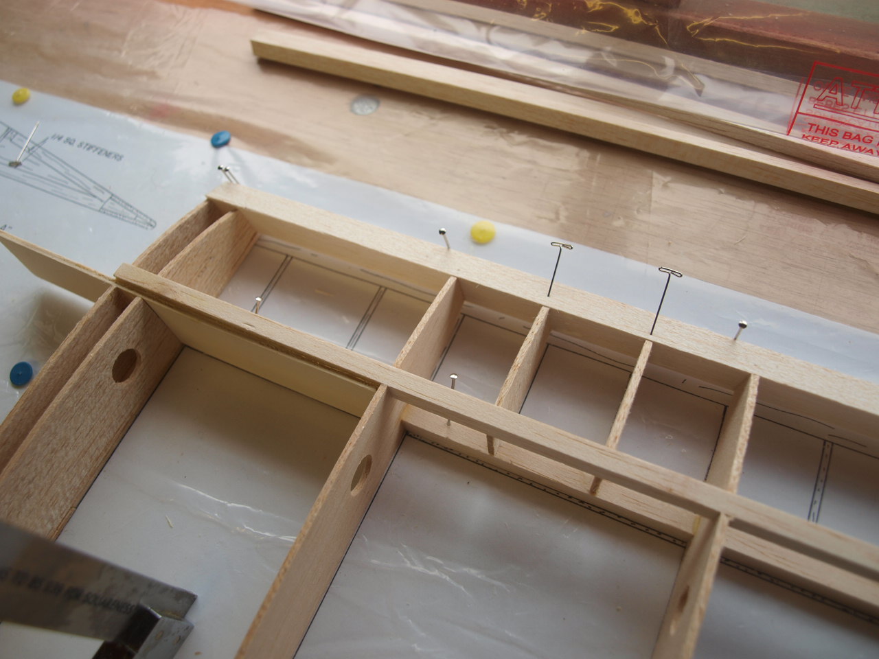
Next I moved onto installing the W3 rear
riblets (picture below) that slotted into position between the top and bottom
rear spars, sitting on top of the previously placed 1/16 sheeting.
Once these where glued in place the rear dihedral brace was located from the kit
and offered up to the rear spars for marking. You can see in the picture on the
right that I have notched out the spar to allow for the top 3/32 sheeting which
sits flush with the top of the front and rear spars and the leading edge.
 |
 |
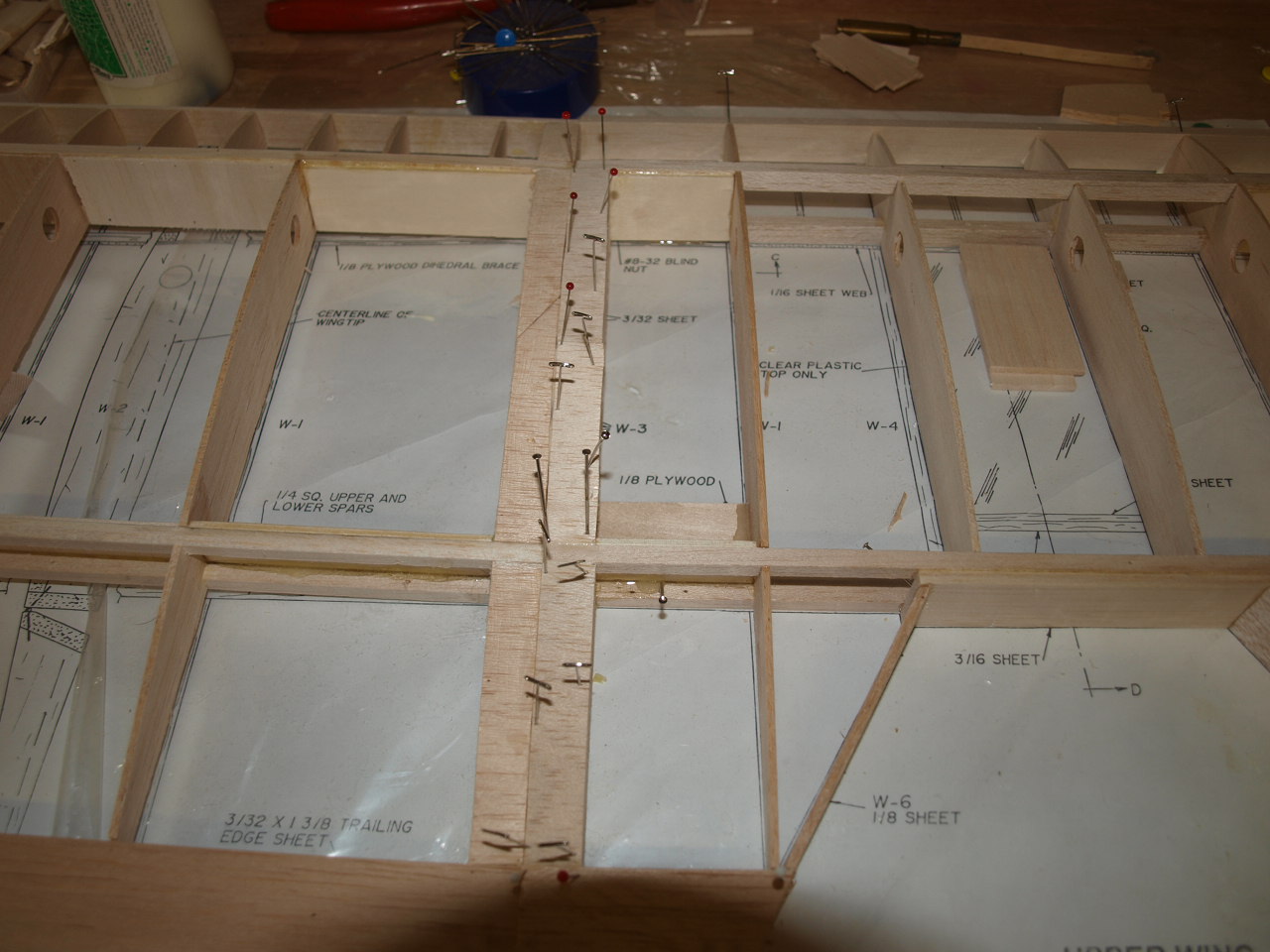
Once happy with the dry fit, the brace is glued into place using 30min epoxy. This provides a very strong bond ensuring the structural integrity of the brace when the model is in the air see picture below.
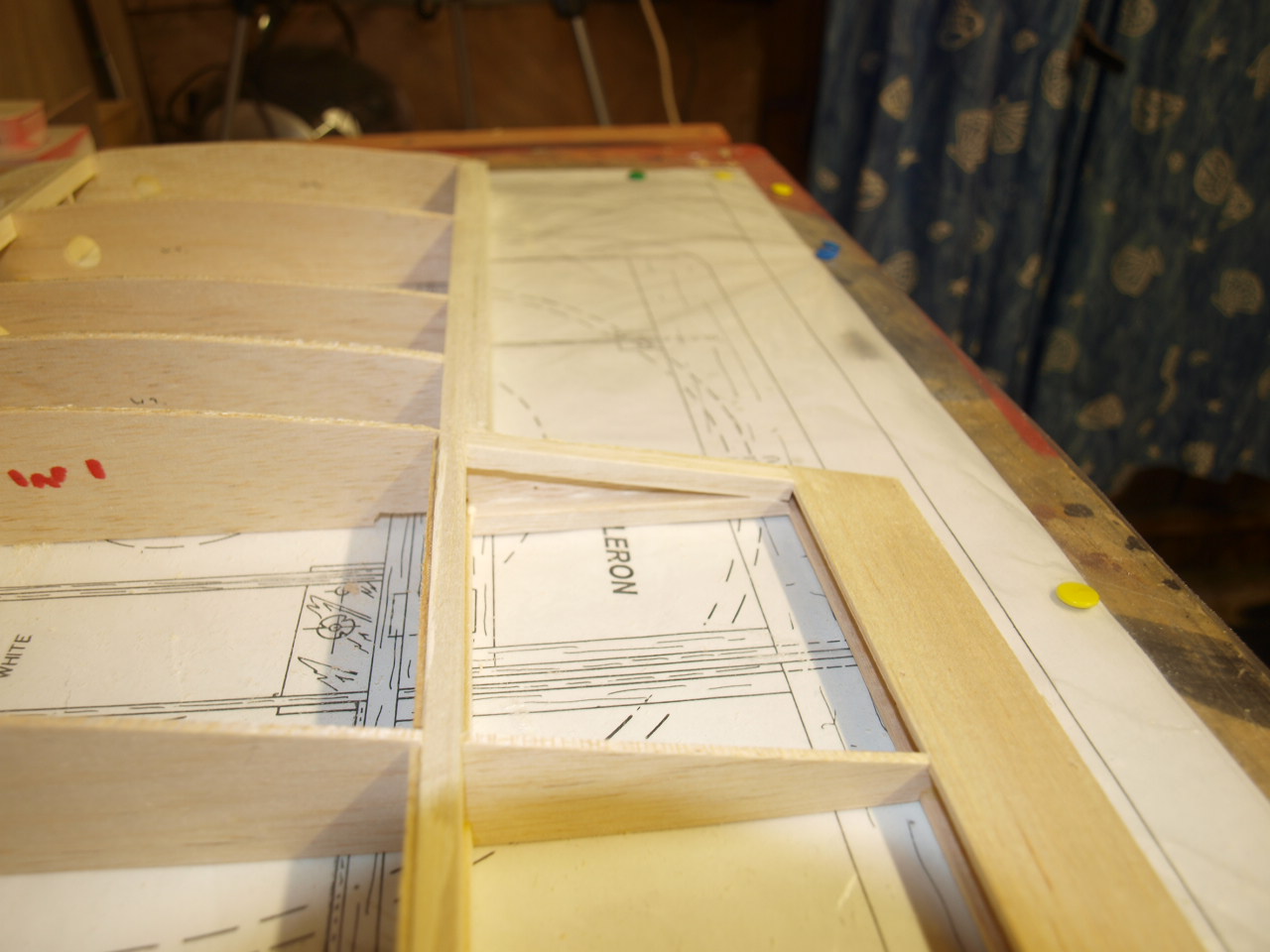
The next picture shows the mid portion of the W3 ribs in place and the front dihedral brace in position. This was fitted and glued exactly as the rear. You can also see in this picture that the aileron has now been constructed.
 |
 |
Wing Construction part 2
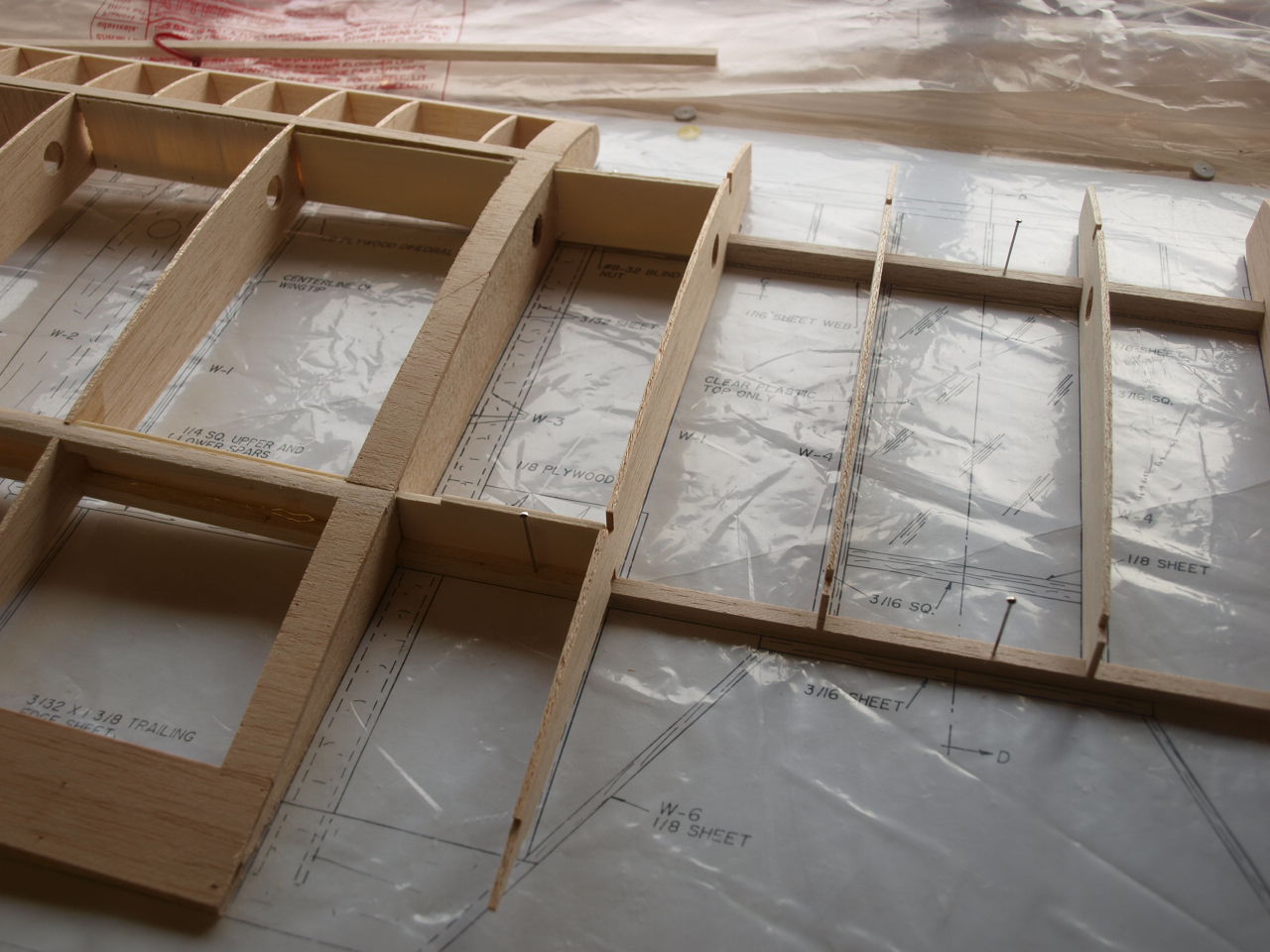
The following two pictures show, firstly the leading edge now permanently glued into position with the false ribs also in place. This was carried out by first cutting the leading edge to the required length and gluing it to the W1 and W2 ribs positioned earlier. The leading edge is profiled with a sloped top edge and this sits level with the top of the ribs. Once dried the false ribs where then glued into position and pined to hold them in place whilst the glue dried.
The second picture shows the two W3 riblets in place, these sit directly on top of the 1/16 sheeting as the other sections of W3 but are not as yet directly glued to it as the rib is profiled and this will need to be done once the wing panel is removed from the board.
 |
 |
Once all the above was cured then the top sheeting is cut to size and glued into position see picture below.
|
|
The next job is to build in the wing tips.
These are pre-cut and supplied as Die cut sheets. To locate these correctly on
to the wing it was required to shim the leading edge end of the tip up by 3/8
and the trailing edge end by 3/16 (only the large tip section, as the small
section located on the aileron, only needed shimming up at the leading edge by
1/8 and sits directly on the board in line with the trailing edge). Once happy
with the fit they are both glued into position and left to cure.
Once cured the
wing tip braces are dry fitted to the top of the wing tip and once happy with
the fit glued into place. Note the small pieces of scrap balsa pined into place
at the back of the last rib to prevent the rib bowing whilst the wing tip dries.
 |
 |
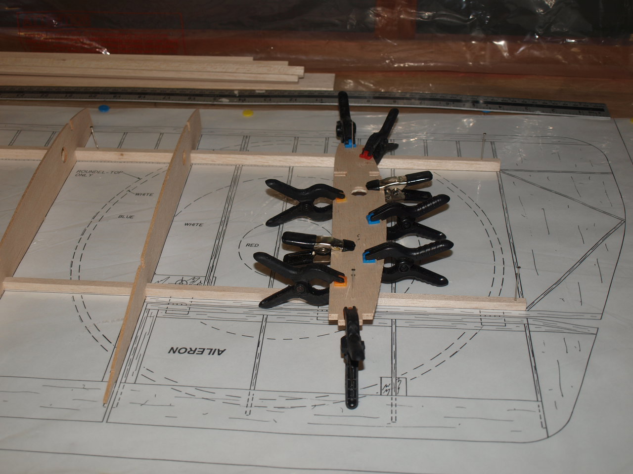
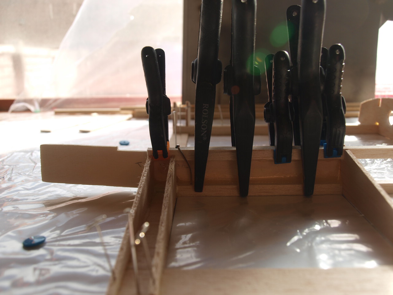
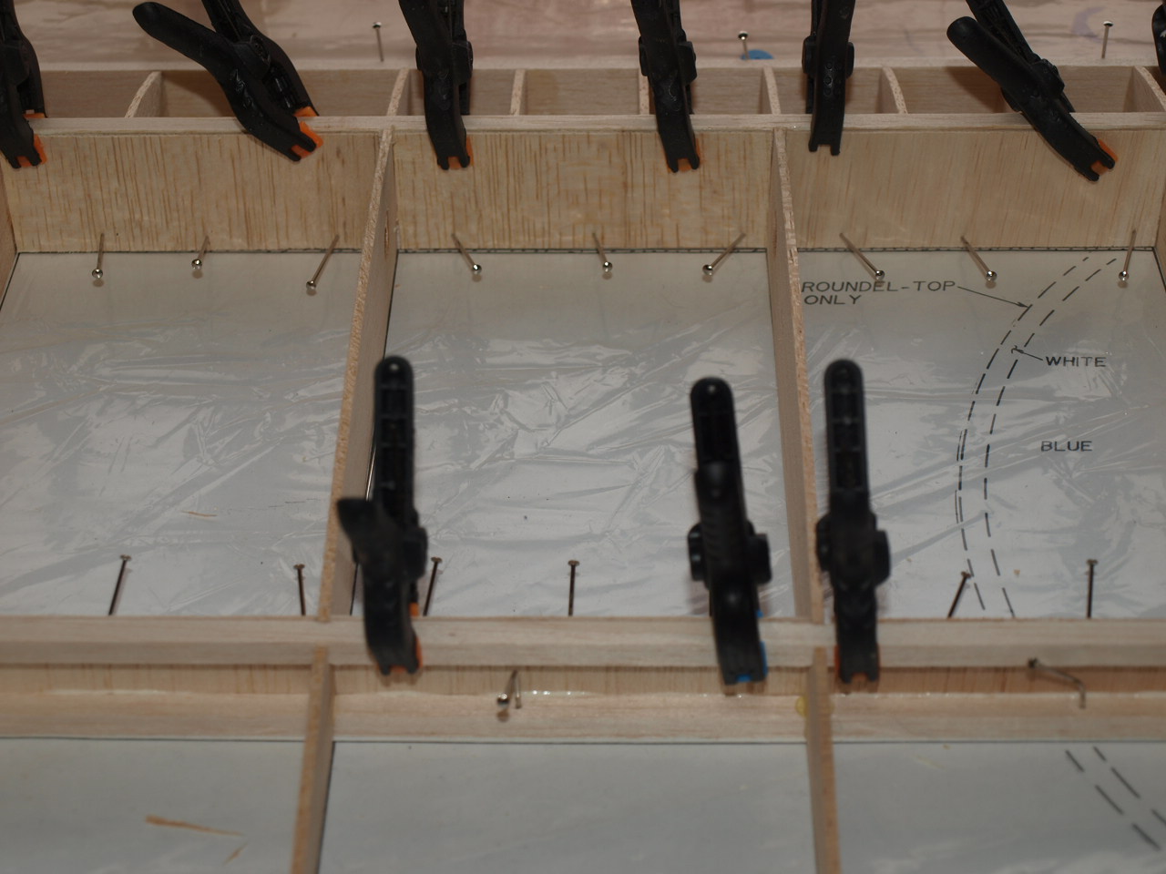
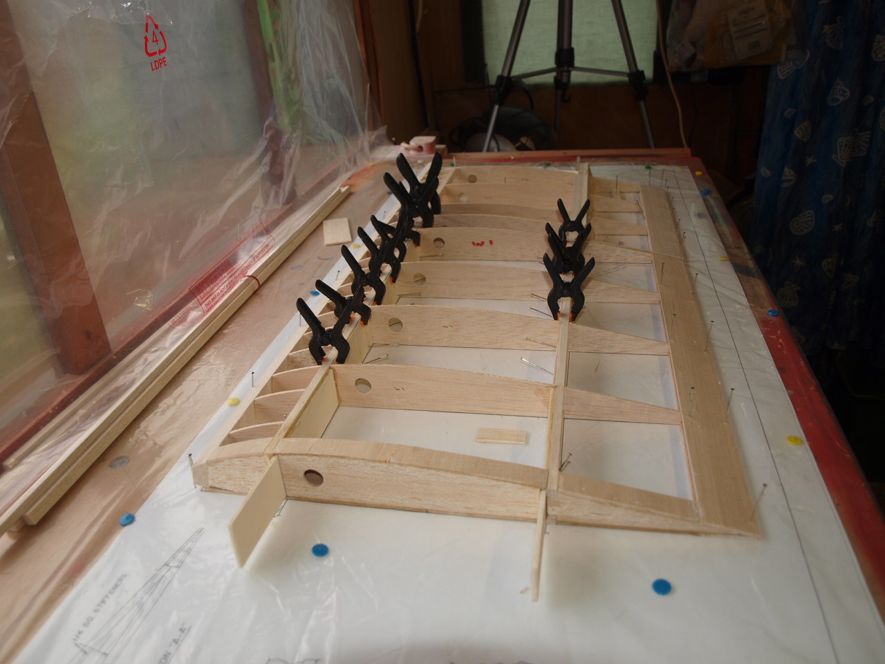
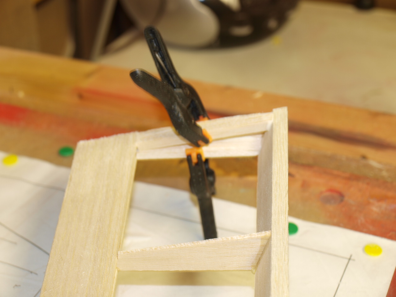
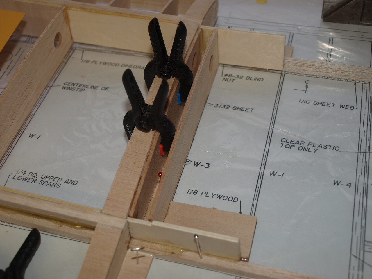
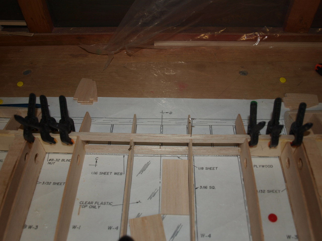
the next two pictures show the shear webs in place and clamped whilst the glue cures
 |
 |
The wing panels basic construction is now complete with only a few minor things to carry out
Wing construction part 3
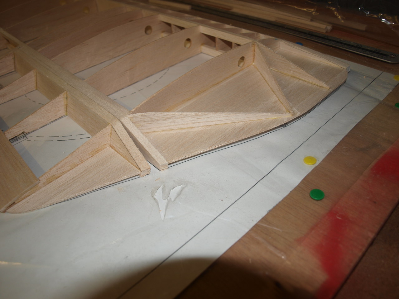
The first picture below shows the aileron leading edges
sanded to their rough shape extending out to the wing tips and also the leading
edges. As mentioned earlier the final sanding will be carried out at a later
stage. The wing is now removed from the building board and reversed.
The second
picture shows notches sanded out to 1/8 depth. These notches are there to accept
the 1/8 x 5/8 x1 1/2 ply strut mounts. I have not glued these into
place as told to do in the instructions as I'm a little unsure at present
what to do. Later on in the instructions they have to be drilled to accept a
captive and I'm concerned at this stage that if glued into place this may cause
me problems later. Hopefully all will become clearer later on in the assembly
instructions.
 |
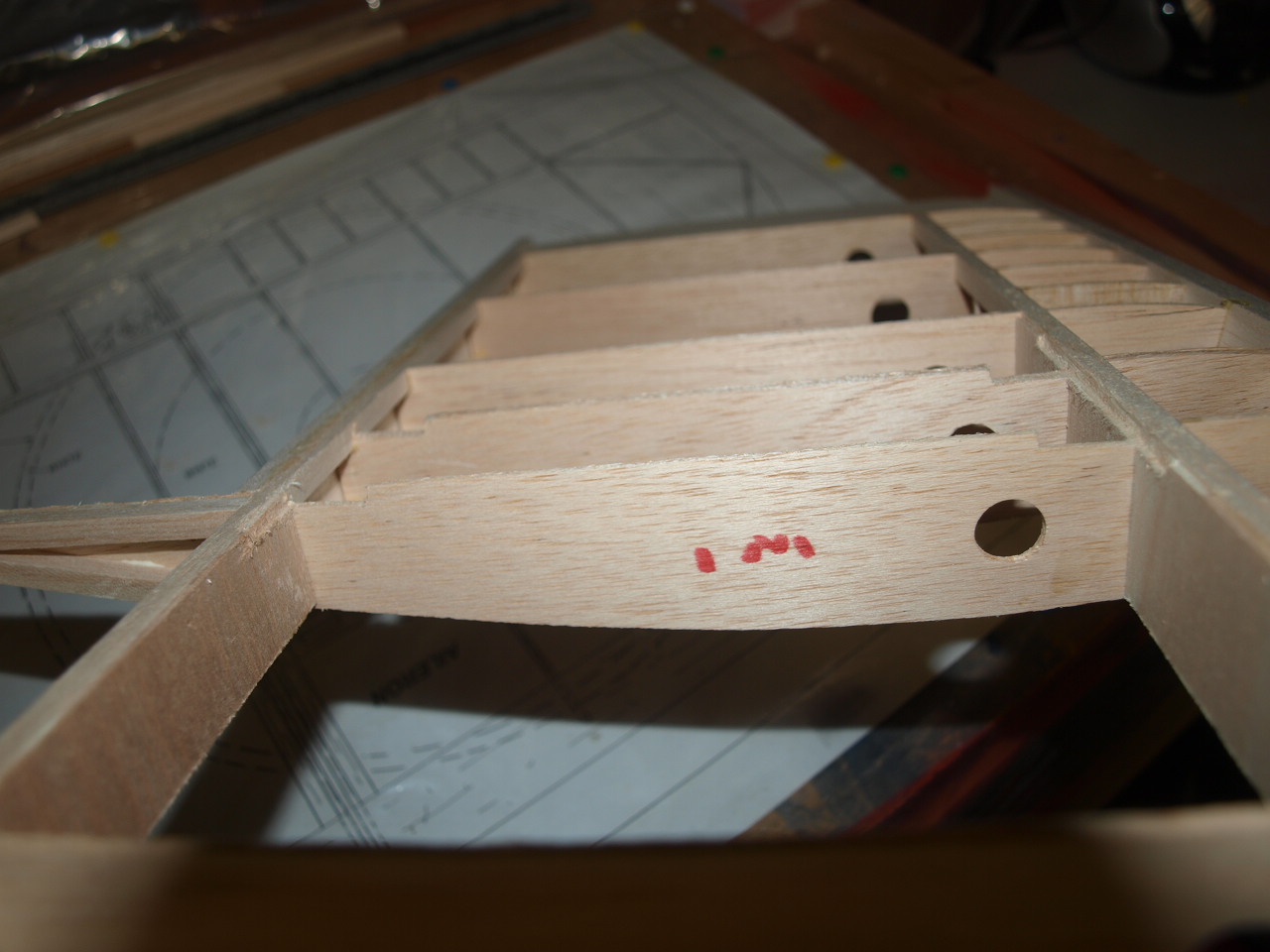 |
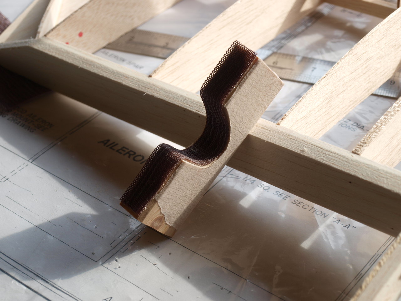
The next picture shows the notch sanded into the aileron rib which will accept the linkage rod mount. I was a little concerned that this did not seem very strong as it is only glued to the trailing edge and the rib, so have strengthened it further by adding to 1/4 x 1/4 hard balsa packing pieces to the either side of the rib and laying flat on the ply mount.
 |
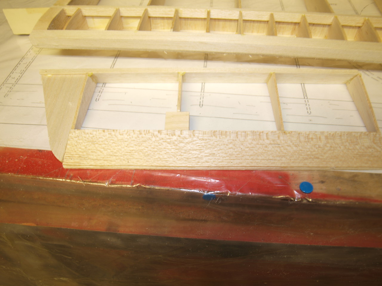 |
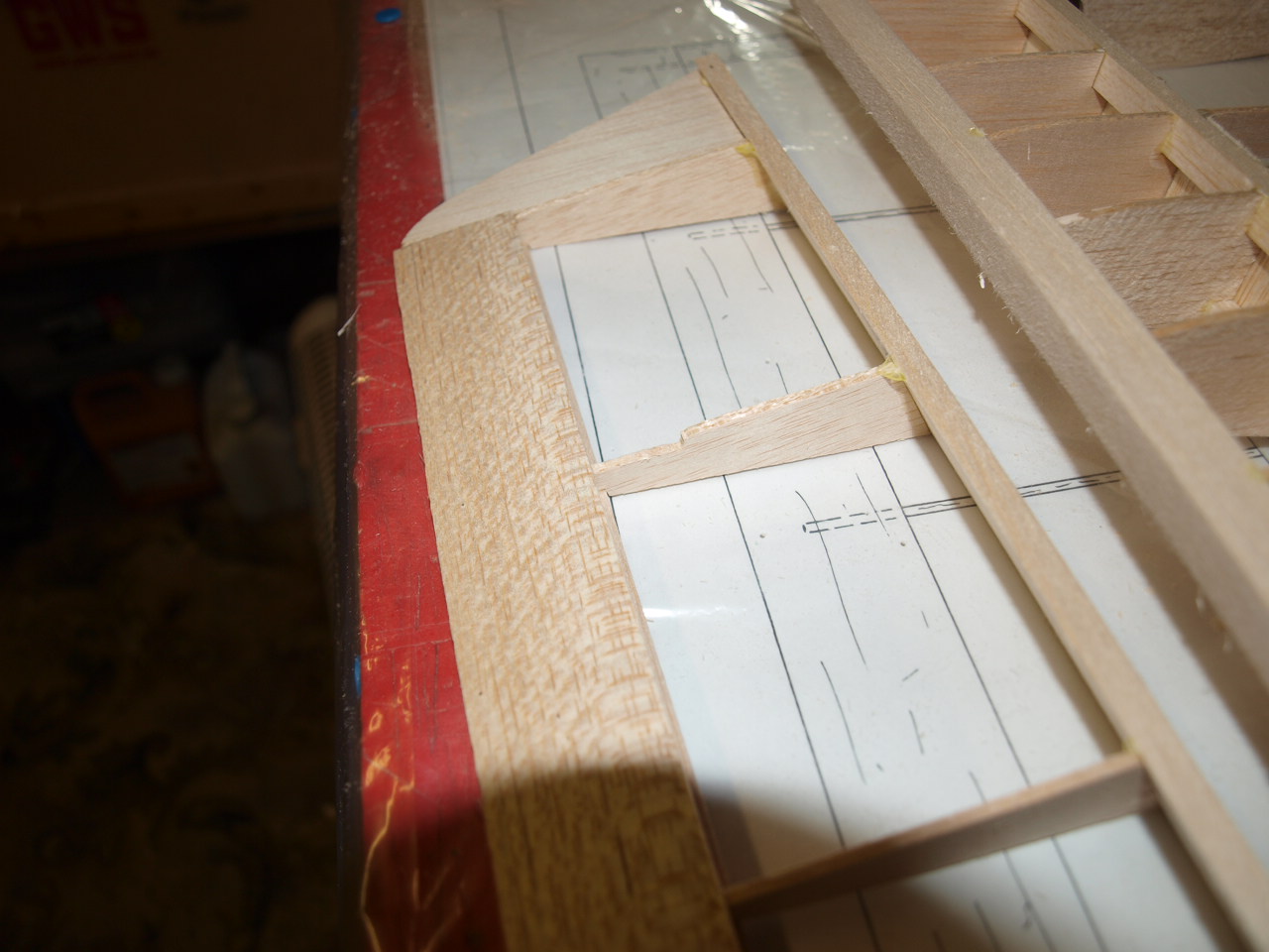
The next picture is just showing ply mounts in place. The next two pictures are showing the now installed 1/4 x 1/4 balsa stiffeners located in the last W1 rib at the trailing edge and also on the aileron. This not only strengthens these areas but gives us something to attach our covering to, whilst also preventing the ribs from being blown out when the covering is tensioned with the iron.
 |
 |
 |
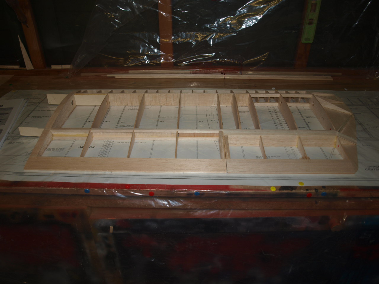 |
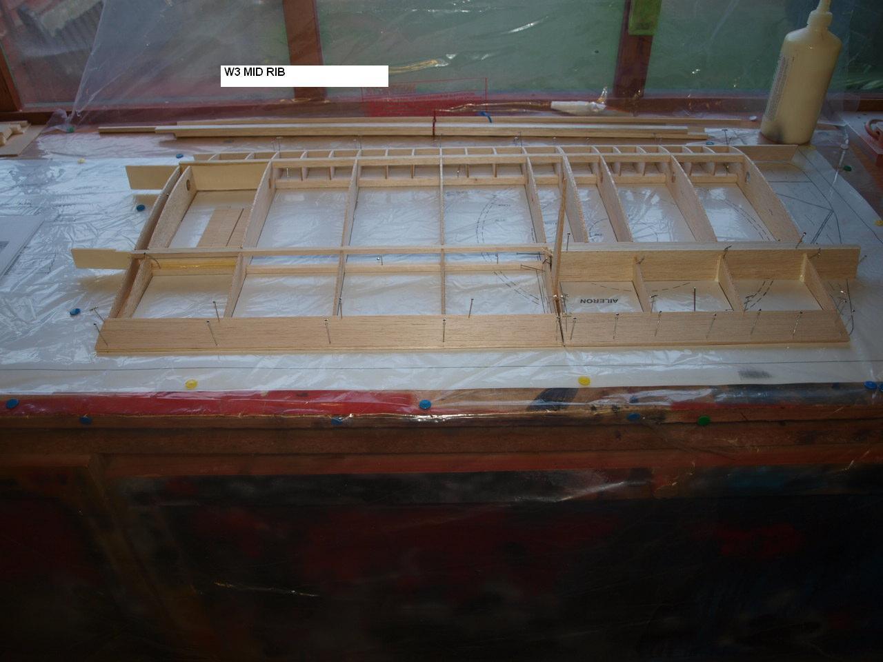
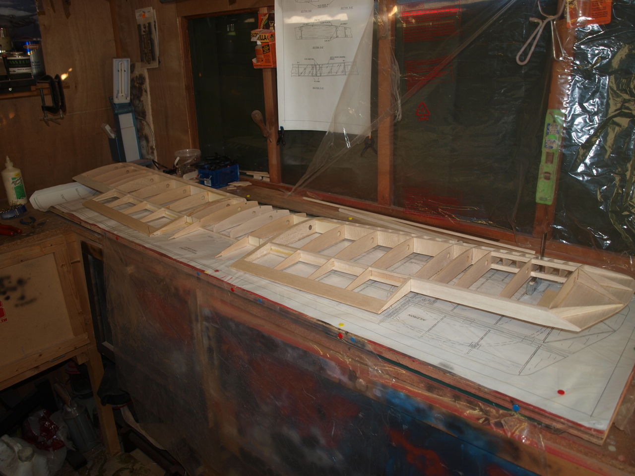
The last picture of this stage shows the finished right hand wing panel ready to be married up with the centre section of the top wing.
The next job for me now is to build the left wing panel. This is carried out in exactly the same manner as above.
Wing Construction part 4
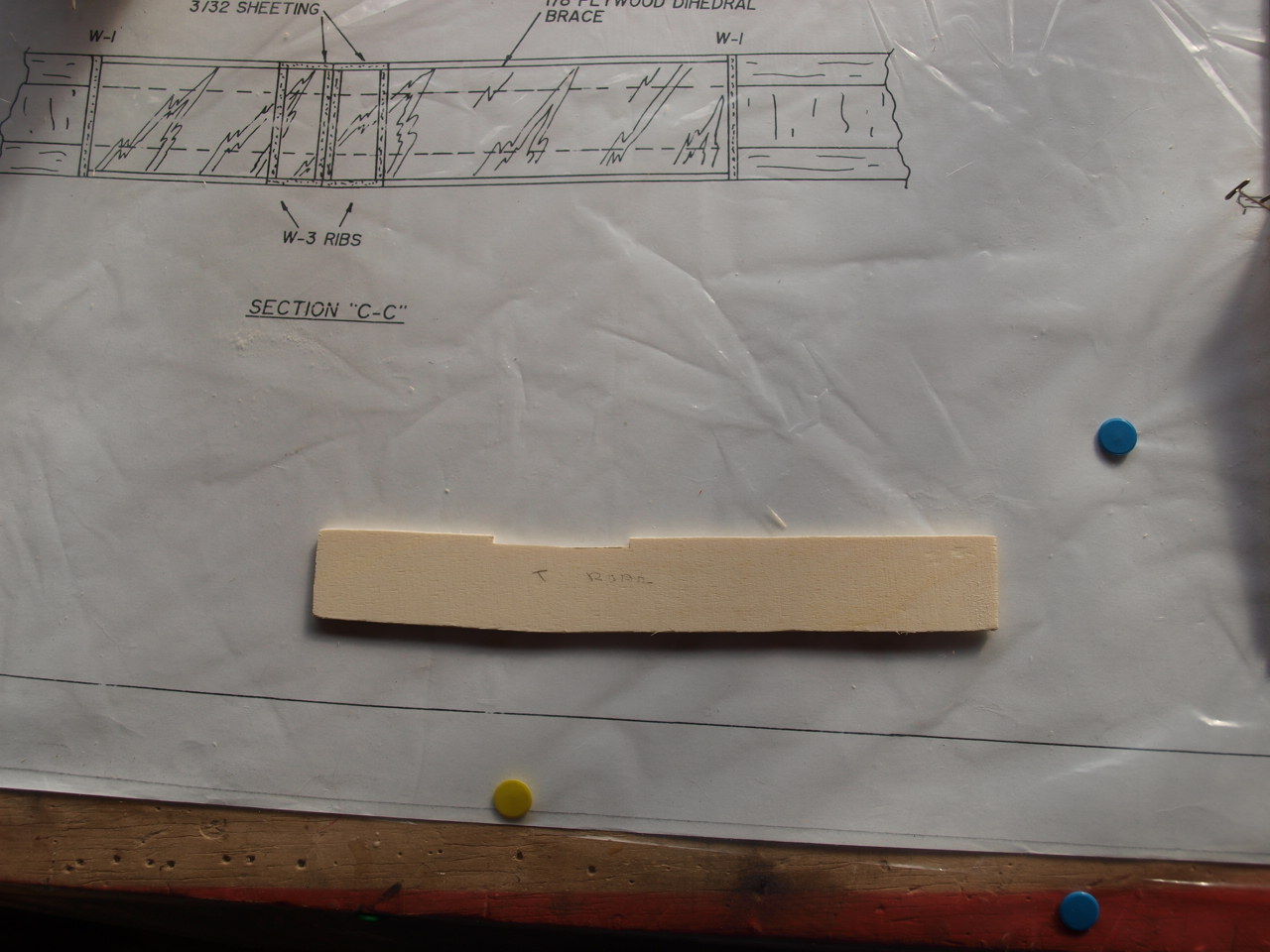
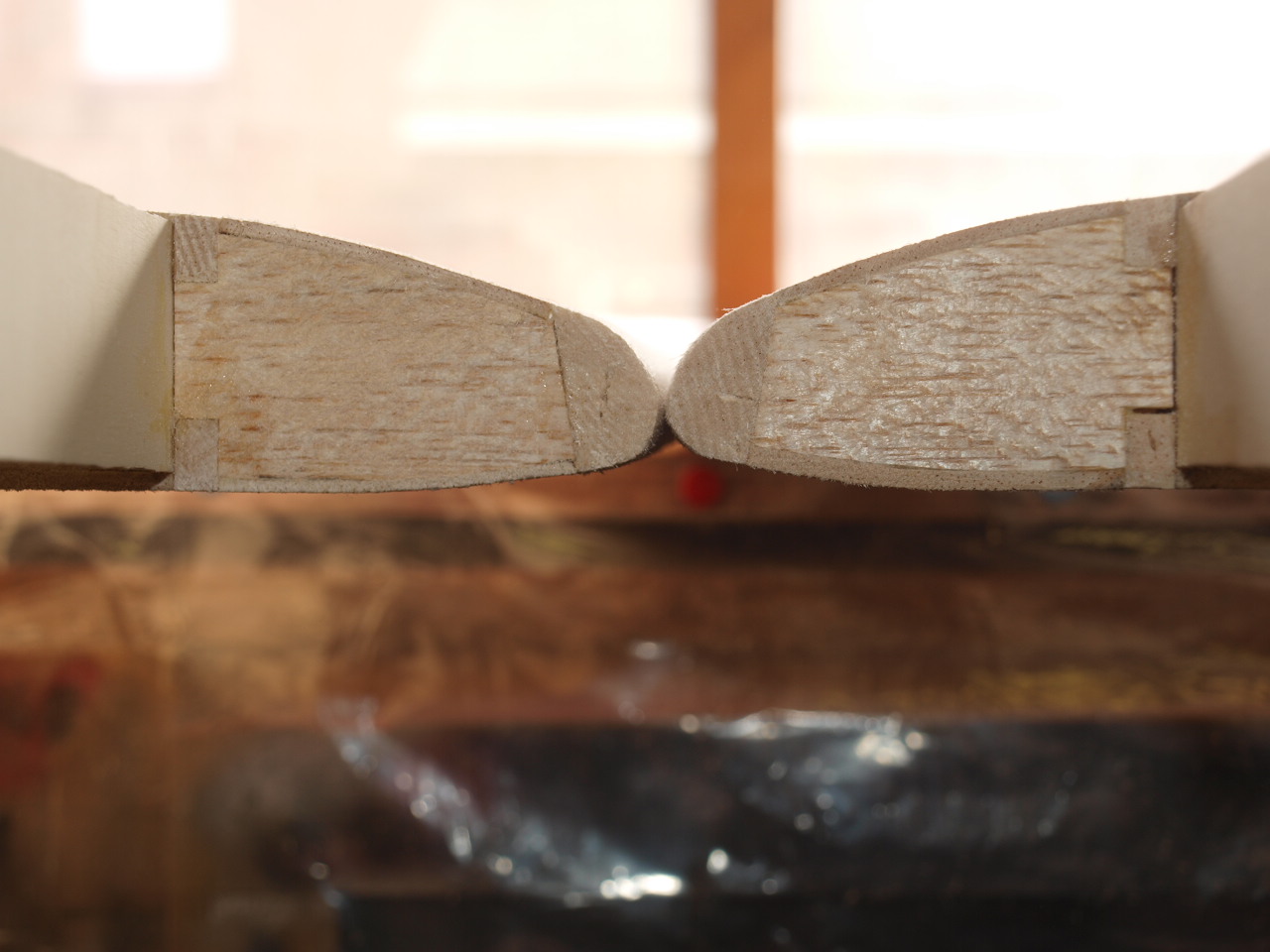
The following three picture show the now completed top wing panels, the sanding block made to sand the final leading edge profile and the root end of the panels showing the leading edge profile
 |
 |
 |
Once this has been completed then the centre section will be constructed and the
to panels joined to this. See construction process below
Centre section construction
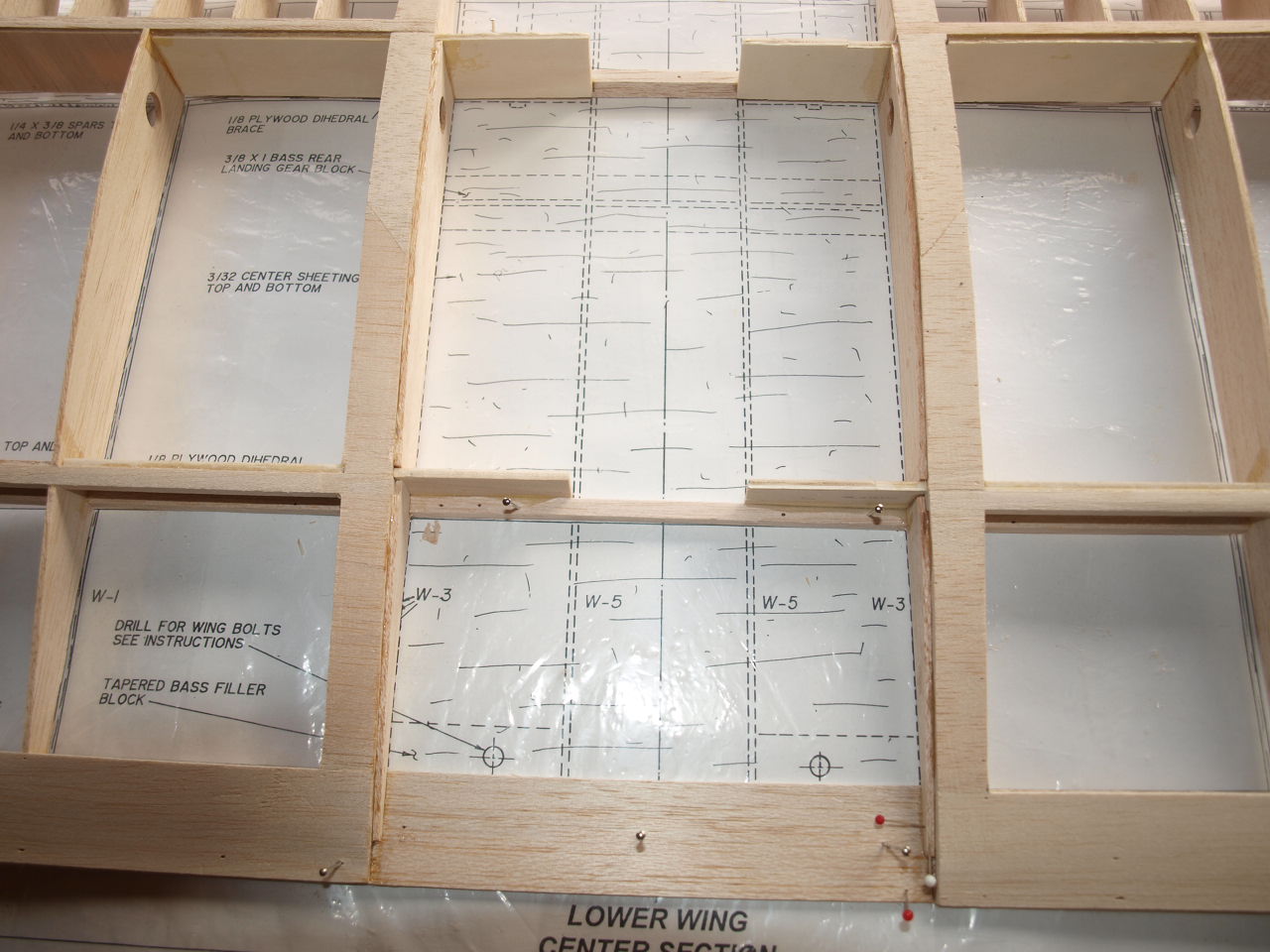
The first job to carry out on this section is
to locate the the 1/4 x 3/8 front spar. This is pined down over the plan using the same system as we did our wing panel main spar. Again once in position
our centre section ribs W1 , W4 are used to aid in the aligning of the rear
spar. This is then pined into position also. See first picture.
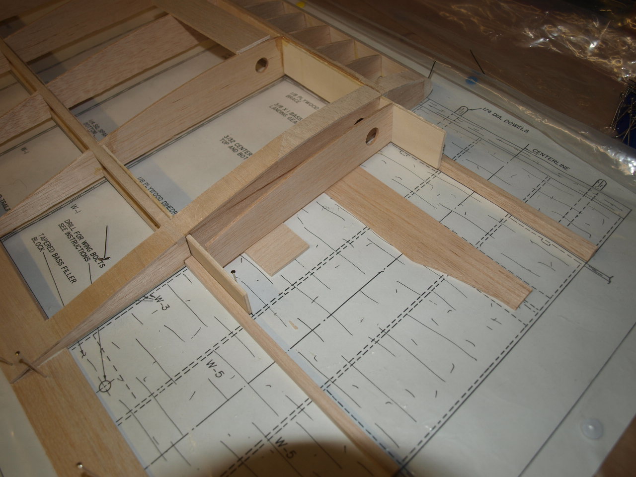
Next I have taken the left wing panel and slid it into position making sure that
the dihedral brace fits snugly against the centre section main and rear spars.
In the next picture you can see that I have elevated the wing tip to 1 3/8 using
an off cut from the wing trailing edge as it is exactly the right dimension
required. This now gives us our correct dihedral as stated in the instructions, also note in the picture that a set square is being used against the inner
leading edge to line up the panel with the plans to ensure that the wing is
neither to far swept forward or back. Once happy with the fit and alignment the
dihedral brace is epoxied (30min) to the front and rear spars.
 |
 |
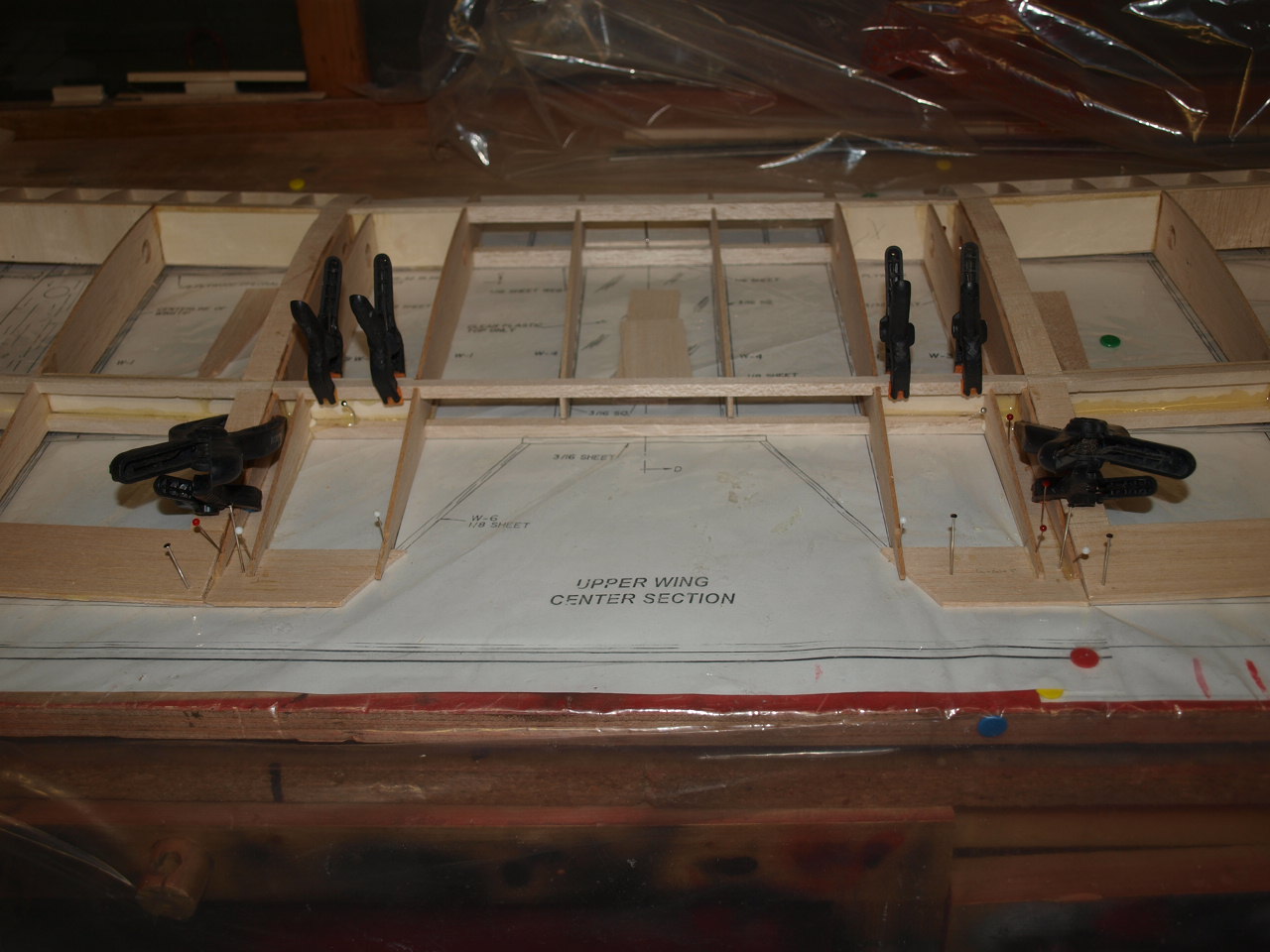
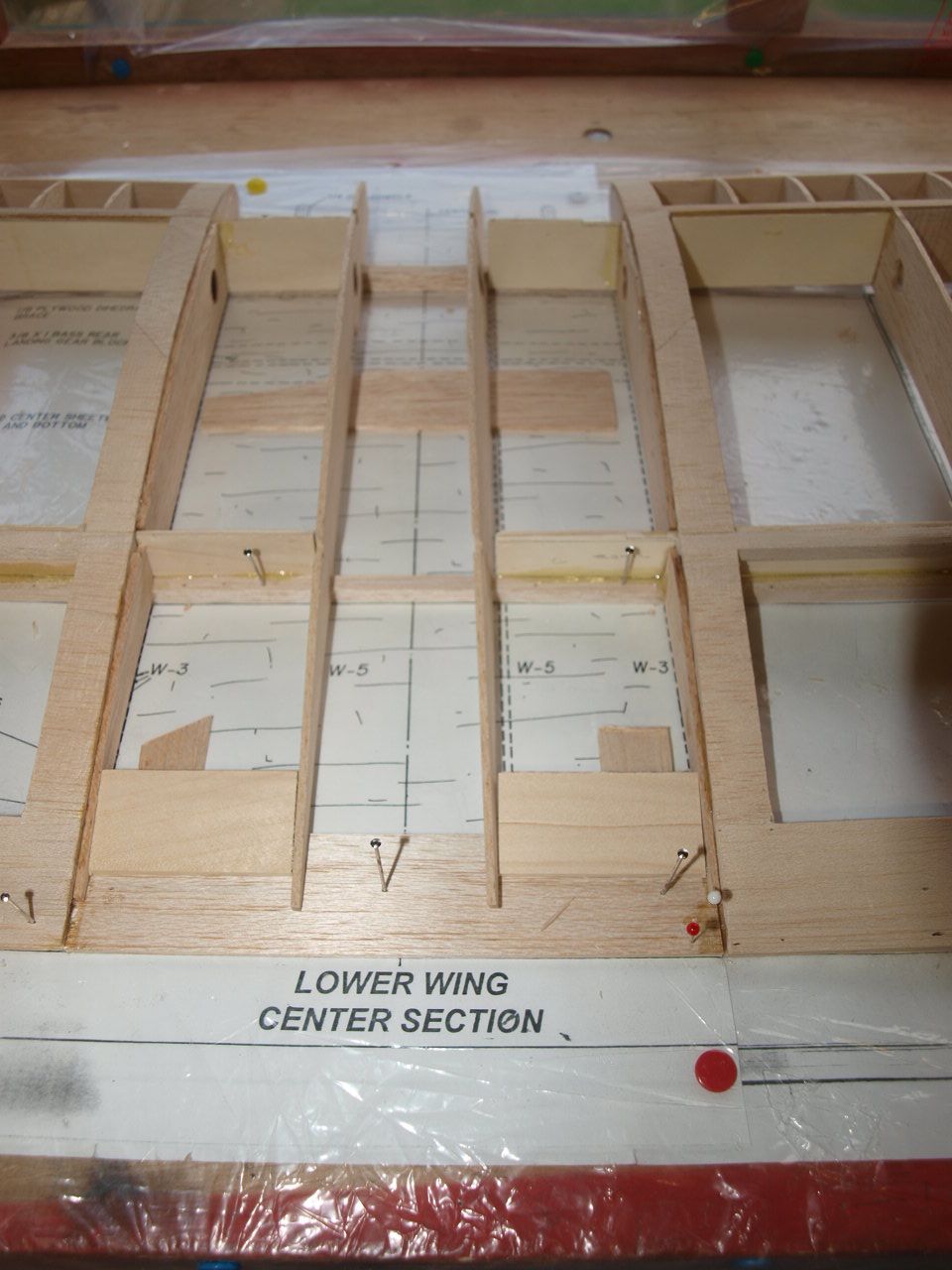
Once the epoxy has cured the next job is to place the cabaine strut mounts into place. The smaller one at the front sits forward of the main spar resting against it and the W3 rib of the wing panel and the rear mount slightly larger rests against the dihedral brace and the W3 rib of the wing panel. See first picture below. These where dry fitted first and the epoxied into place (30min)
The bottom sheeting strips where then placed into position as carried out in the wing construction and then the two W3 ribs located into position, one butt against the W3 rib of the wing. For this I used epoxy as this area is where a lot of load will be when the model is in fight. See second picture below.
 |
 |
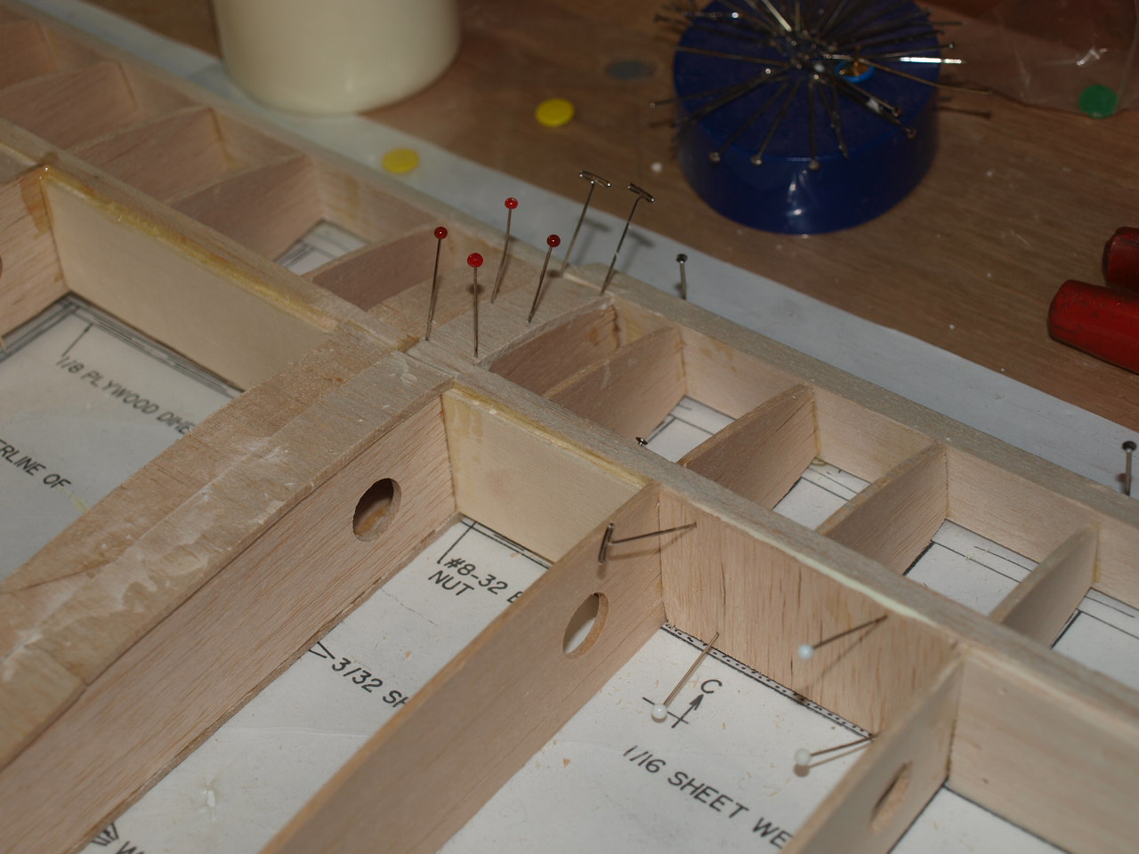
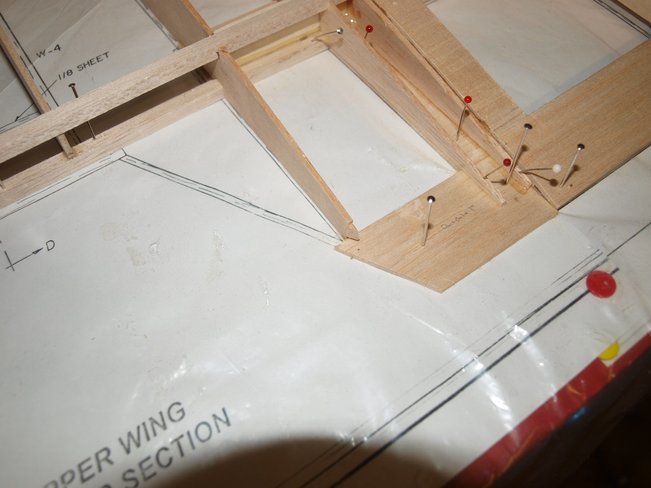
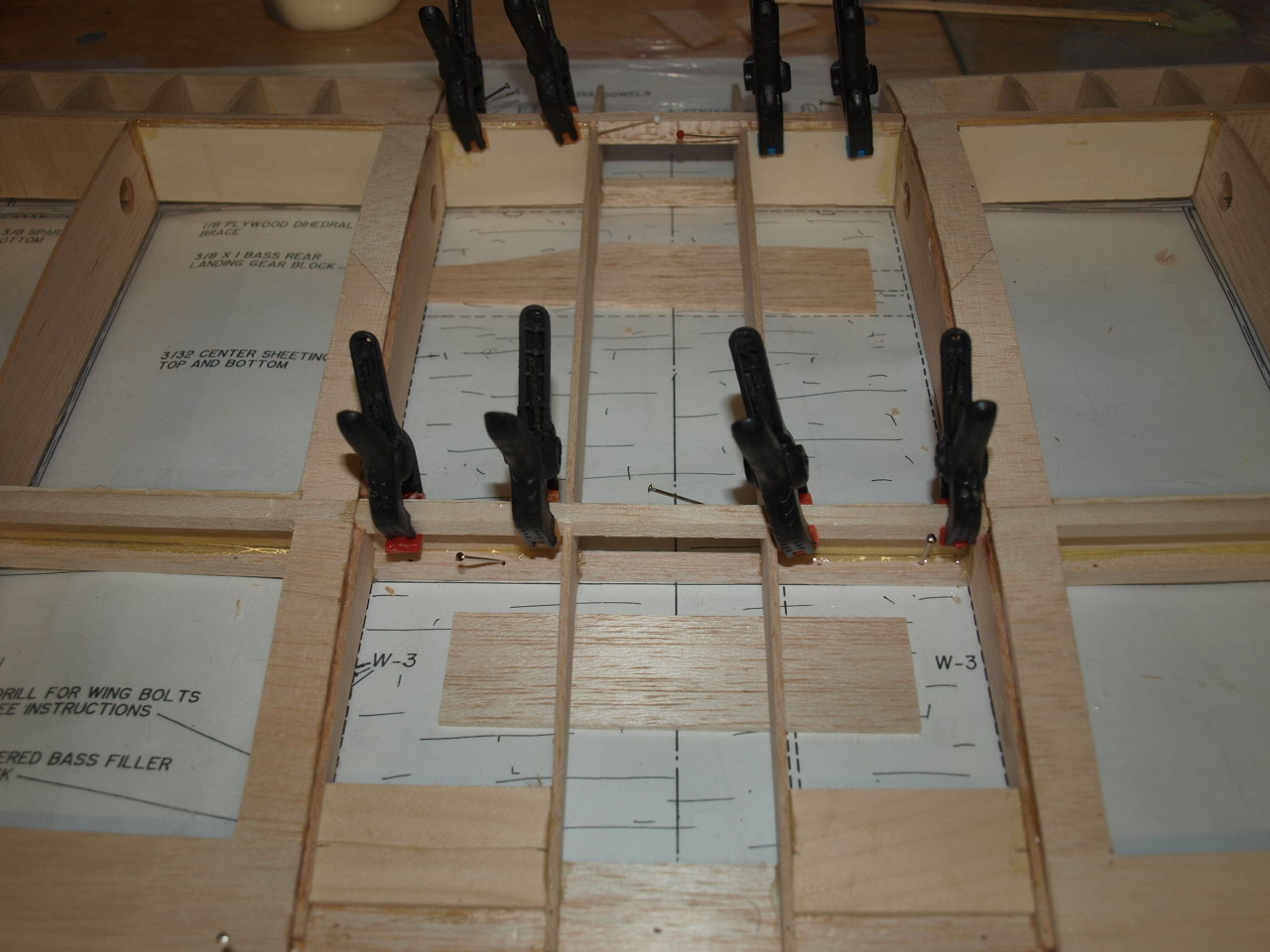
The picture below shows the W1 rib now in position having been notched out where it sits over the cabaine mounts, this notching was also carried out on the W3 ribs prior to installation.
Once at this stage the structure is left to
cure fully over night.
I will have to remove these now joined sections
from the building board and re-site the plan in a manner that will provide me
with enough room to introduce the right wing panel to the centre section,
so that I can carry out the same building sequence as just explained. (my
building board is not long enough to set up both panels in one go)
|
|
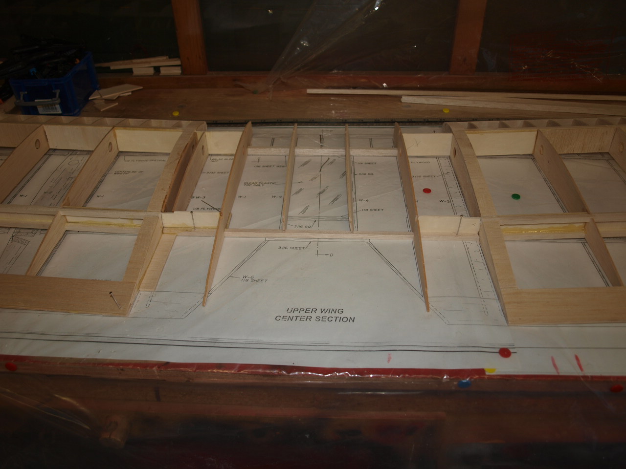
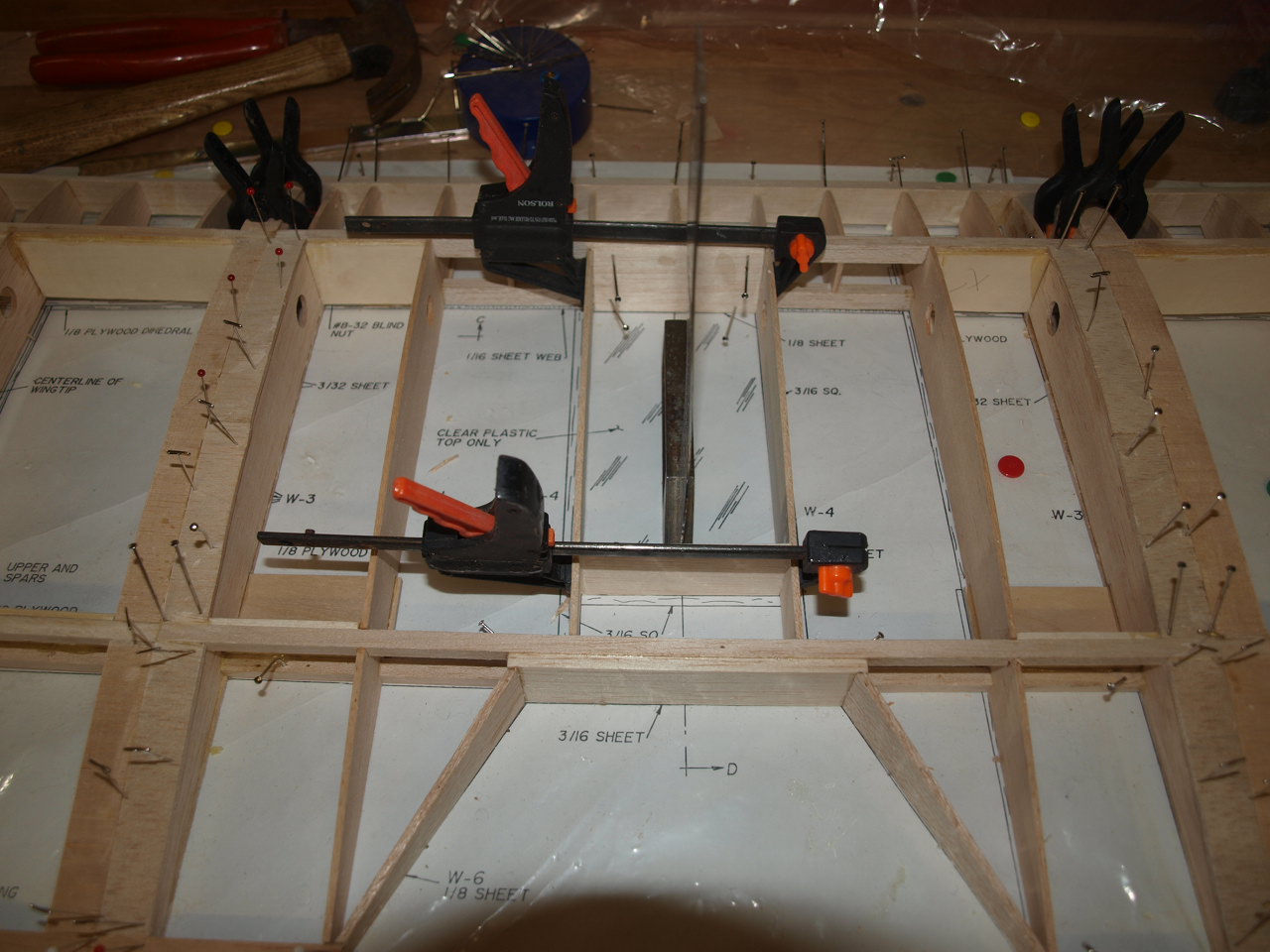
Wing and Centre section construction part 1
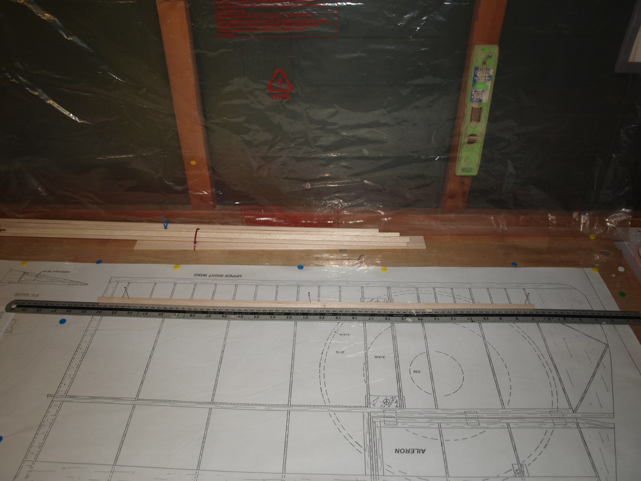
These next two pictures show the plans and the wings now in position. To ensure that the plans lined up, I used a long ruler (3ft) and laid it along the leading edge of the right wing plan and then married up the left wing and centre section plan, again using the ruler and leading edge as a guide. Once this was carried out and the plastic cover put into place, both the left wing with the now attached centre section was relocated onto the plan and pined into position, checking again at the wing tip leading edge that all was square. Next the right hand wing panel was offered up to the centre section using the same method described earlier when we joined the left wing panel.
 |
 |
The next picture below shows the braces glued into place again using 30 minute epoxy. The second picture shows the two W3 ribs glued into position as previously carried out on the left side of the centre section.
 |
 |
Once the above had cured the trailing
edge peaces are cut to shape and size and glued into position.
Next both sides of the centre section have the rear W3 riblets are glued into
position.
 |
 |
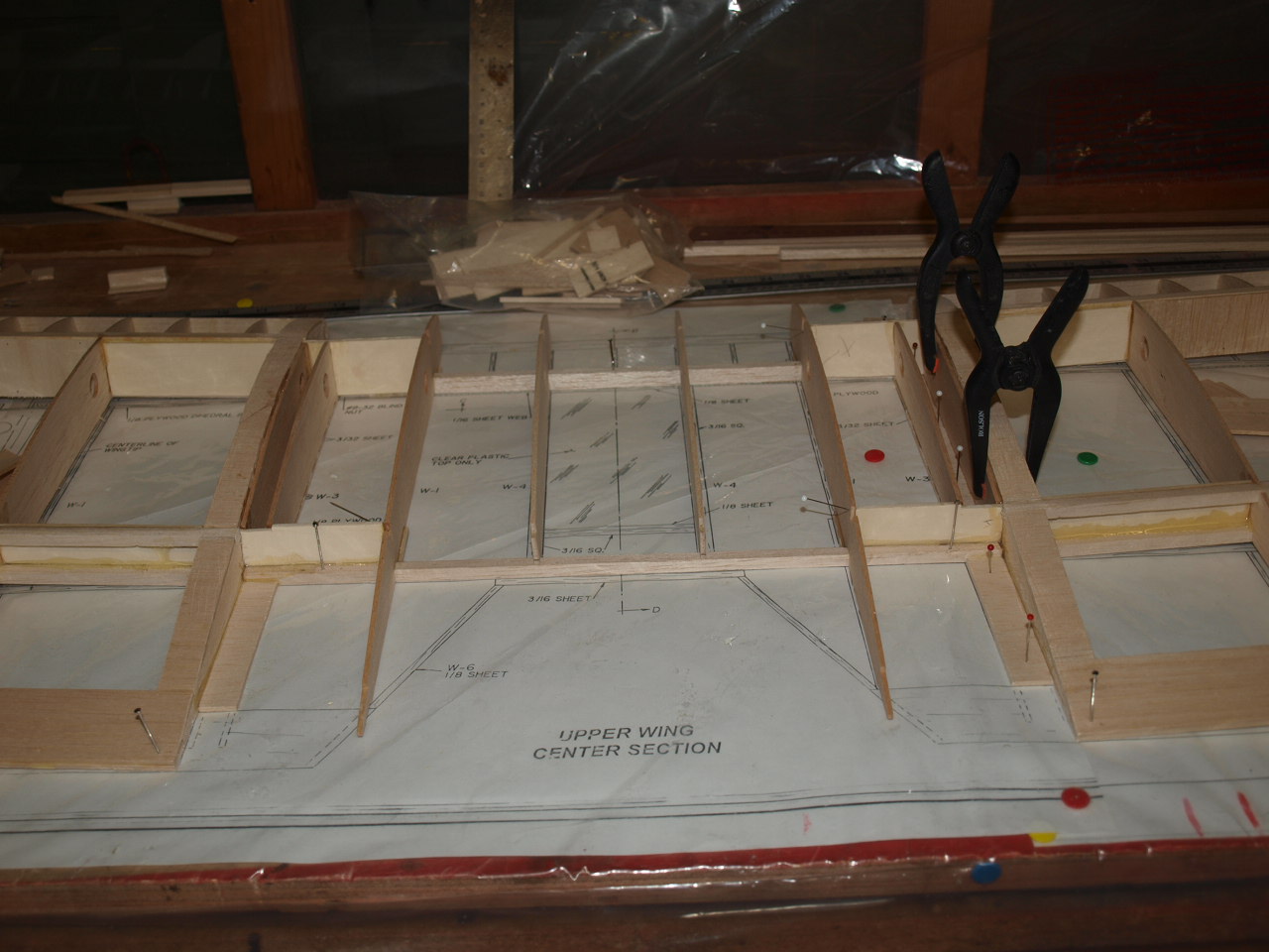
The picture below shows both sides now at the same stage of the building process. Also note that the rear spar has also been glued into position at the W3 and W1 rib locations. but the W4 ribs are still only at the dry fit stage along with the front top main spar that you can see in place. These parts will be next on the agenda but at present I'm not quite sure about the make up of the central part of the centre section.
 |
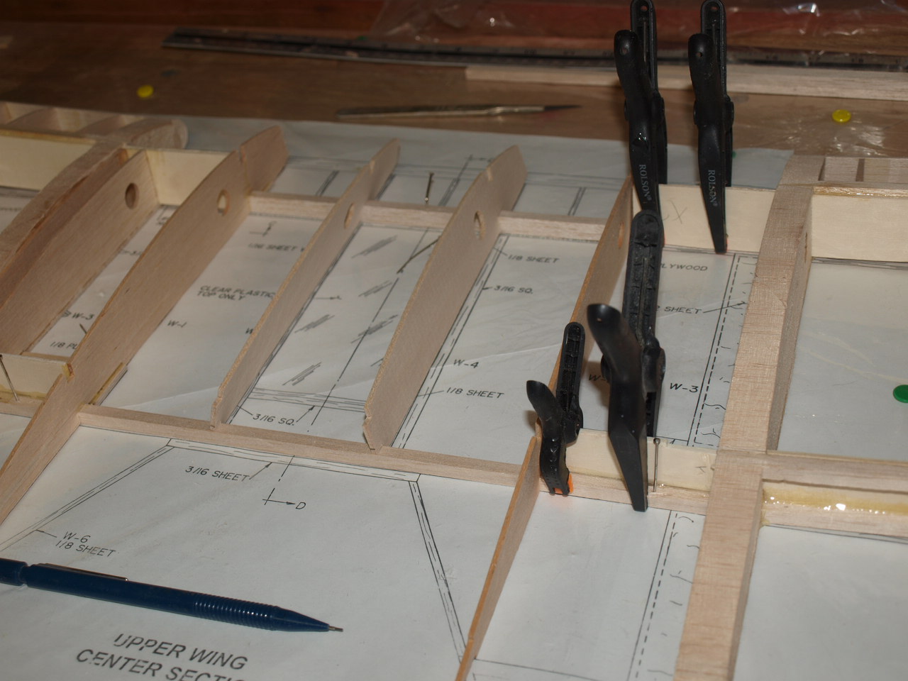
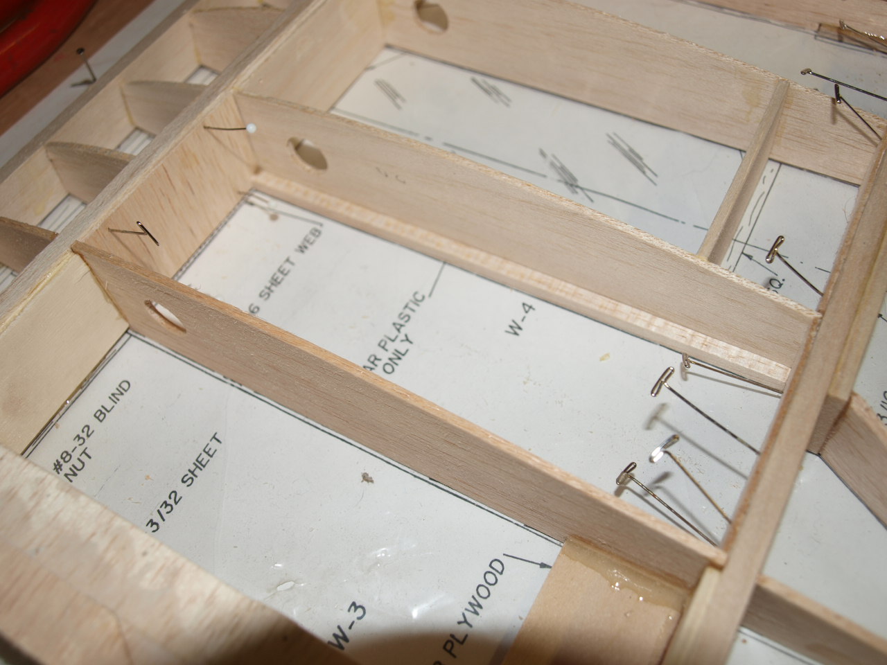
Now happy with with what to do the the W4
ribs a permanently glued into position (note the slight camber of the top spar
this is as the full size aircraft.
The next picture shows the rear of the W1 rib cut to a profile where the W6 rib
will meet with it. this was done using a small razor saw.
 |
 |
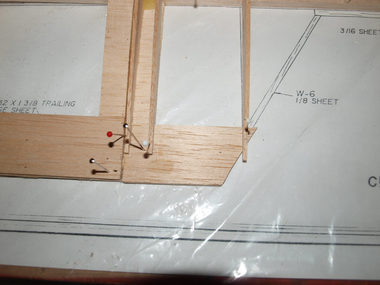
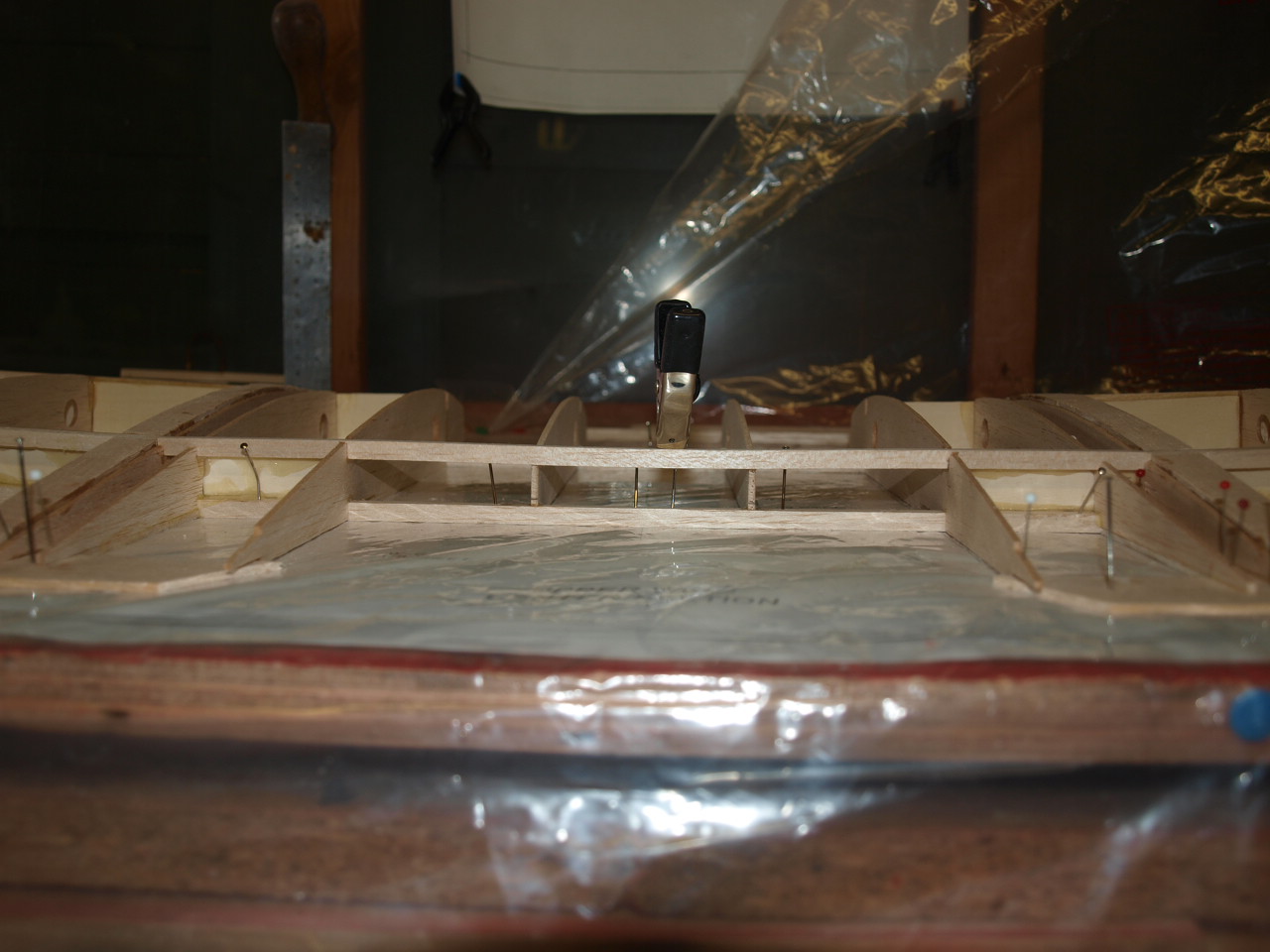
Once this was done the W6 Ribs where dry
fitted along with the 3/16 x 4 1/2 x 1/12 balsa brace that sits butt against the
top and bottom rear spars. See Second picture below.
This reveals that the W6 rib where it meets the brace needed to be profiled
along its edge to give a snug fit. See first picture.
Once happy with the dry fit all was glued into place.
 |
 |
Next the front top main spar is glued into position, again note the slight camber.
 |
Wing & centre construction part 2
Once all is dry the trailing edge top sheet is shaped and glued into position along with the top sheeting over the W3 ribs. This is carried out on both sides of the centre section panel. See pictures below
 |
 |
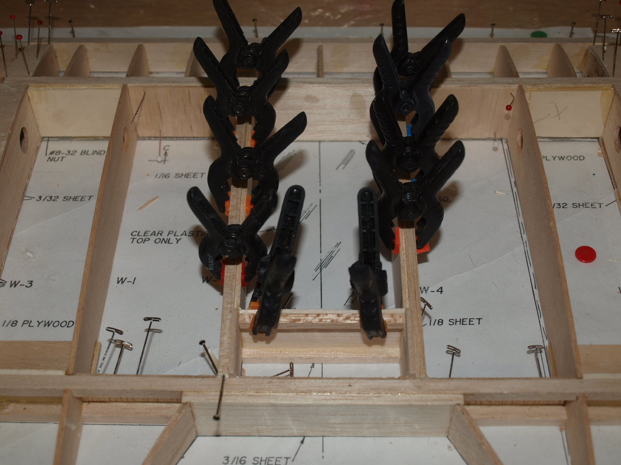
The centre part of the panel is left open as per the full size and a clear acetate sheet is located on the top section of the wing. This area caused some confusion as the two W4 ribs did not sit flush on the plan as per the cross section on the plan suggested. They where raised of the plan at the rear spar by about 1/16 . Before I started on adding the 1/8 balsa sheets and 3/16 sq stiffeners to this area, I asked a fellow modeller friend to give me his opinion on this area (Another good reason to belong to a club). It was jointly agreed that the two W4 ribs must have been die cut slightly smaller than the plan suggests. Having cleared that up I proceeded to install the two balsa cross pieces 1/8 x 3" 1/2 x 1" 1/2 at front spars and 1/8 x 3" 1/2 x 1" 1/4 in front of the rear spar as per its location on the plan and glued and clamped into place.
Once these had cured, the two lower 3/16 sq stiffeners where glued into place level with the plan. The 1/16 this will leave under the rib will be filled later once the wing is removed.
 |
 |
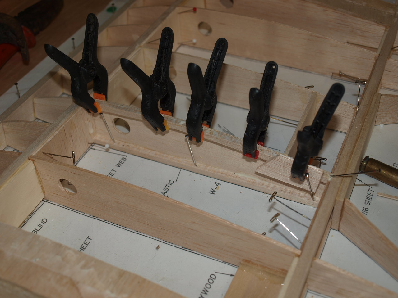
The top rib stiffeners need to follow the contours of the W4 rib. To achieve this it was necessary to soak the balsa strips in warm water and then bend them into the approximate shape and pin them to the building board until dry. once dry they can be removed and glued and clamped into their location as seen in the pictures below.
 |
 |
The last couple of jobs left where to glue in the leading edge, false ribs, W3 riblet top sheet and the shear webs. These operations where carried out exactly as per the wing panels described earlier.
|
|
Once all was cured the whole wing section was removed from the board and the leading edge of the centre section sanded to shape. The wing is now put into storage while the bottom wing is constructed
Wing & Centre section construction part 3
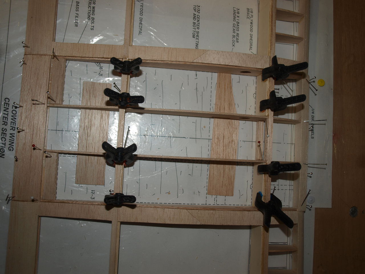
Lower wing construction
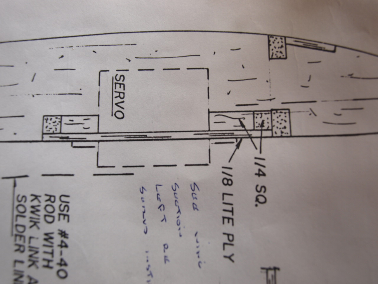
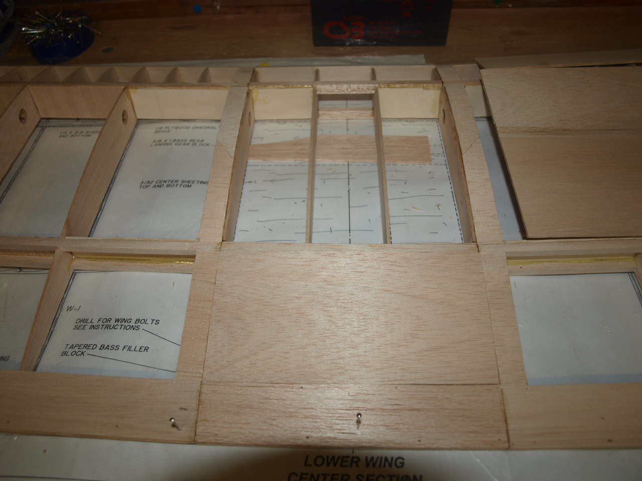
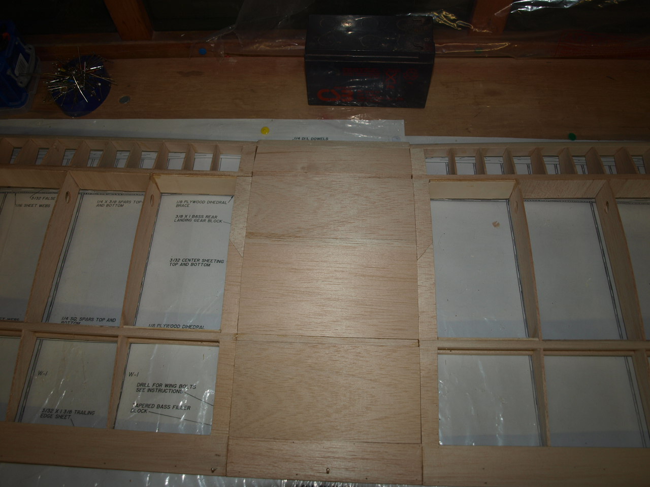
As mentioned above the basic construction is the same as the top wing, with only a couple of differences to the bottom. The first is the need to house the servos for the ailerons. On the plans the servo housings are shown with a proportion of the servo protruding out from the wing making it very visible see pictures of plan below.
 |
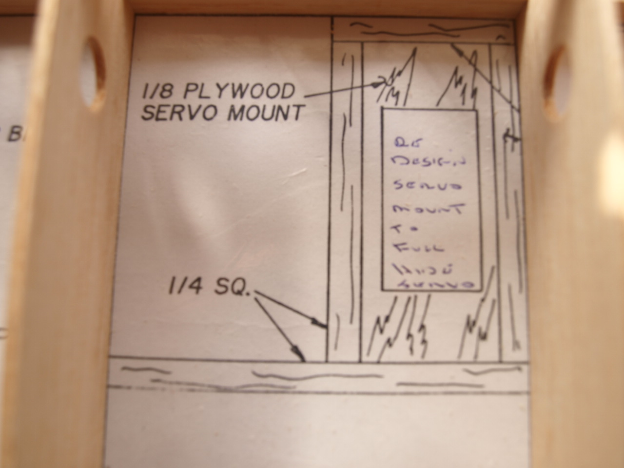 |
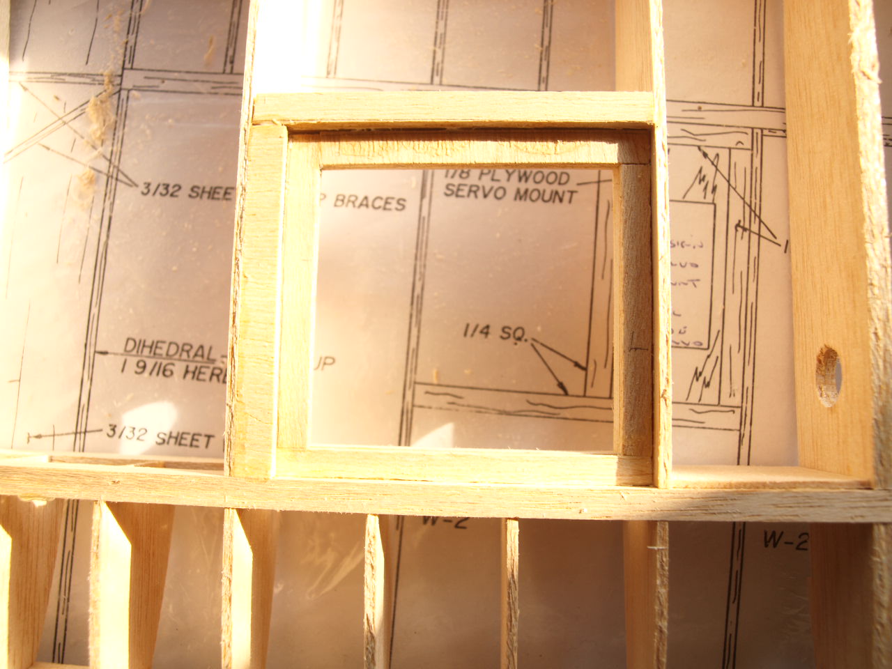
As this detracts from the scale appearance of
the model I have decided to redesign the mounting so that the servo body is
totally enclosed within the wing, with only the servo arm protruding.
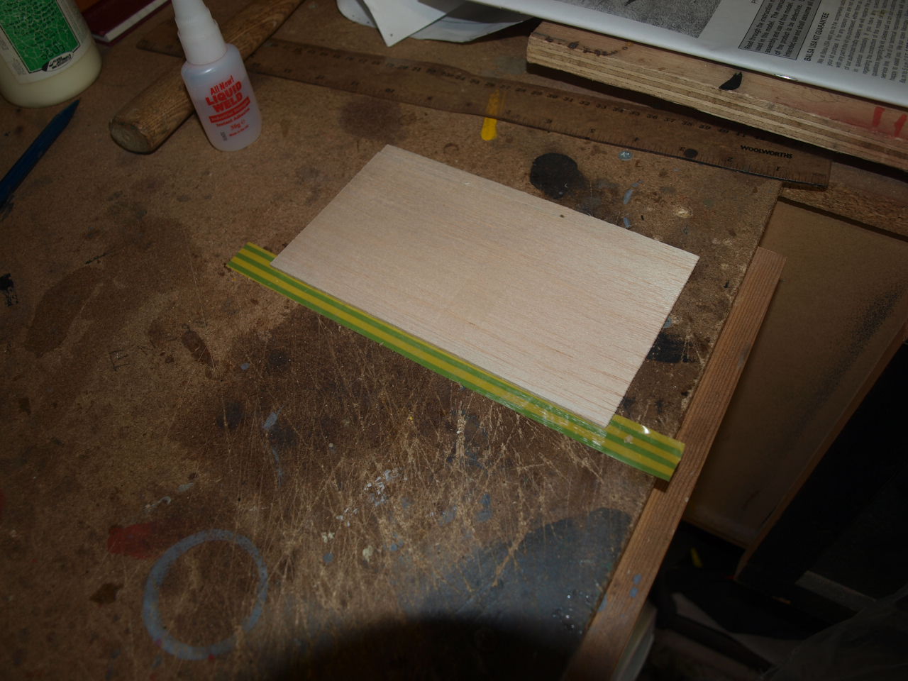
This was achieved by first cutting out a square of liteply to a suitable size
that will comfortably hold and support the servo. See picture below.
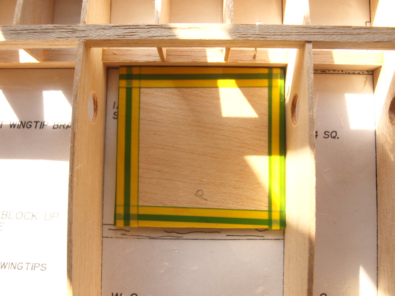 |
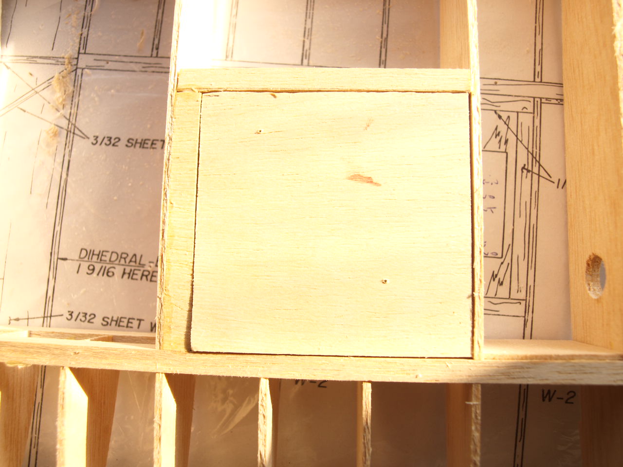
note: this has been masked with
electrical tape around its edges as I will be laying ply and balsa strips
around and over this part in the following stages. |
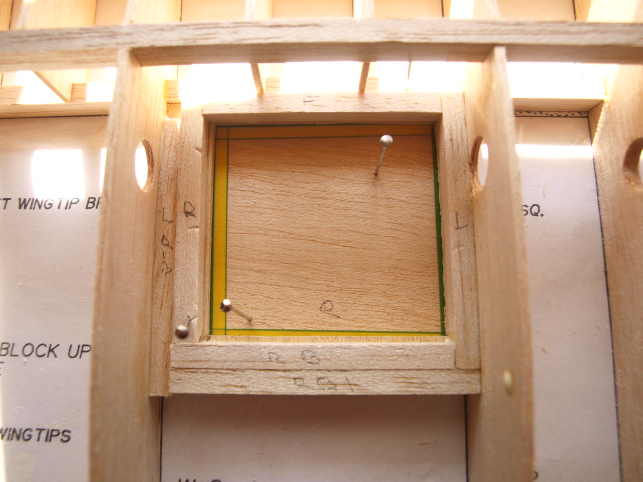
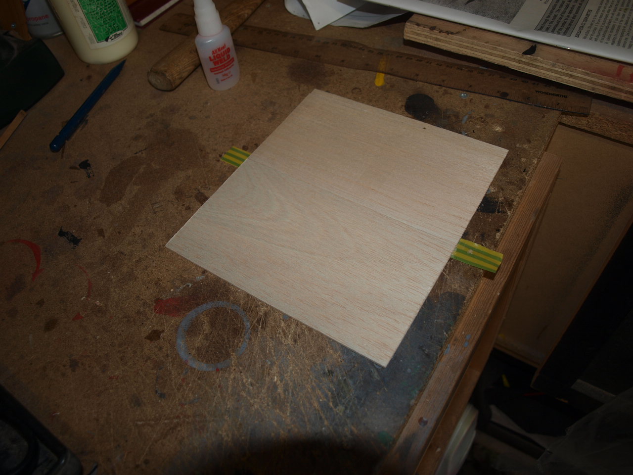
Once this part is in position I next placed liteply strips directly on the plan and butted against the two open edges of the mount. These where cut an 1/8 of an inch wide and the reinforced with 1/8 sq balsa directly glued on top. see picture 1 below
 |
 |
Once in place then the same procedure was carried out again but this time with the liteply and balsa strips placed directly on top of the mount. As you can see from picture 2 once removed from the board and reversed this gives me a nice recess in which the mount can sit and at the same time provide a nice area where the covering can be secured to.
 |
picture showing mount in place |
The next difference in building of the lower wing is the aileron, where I have to add a ply horn mount to the aileron. Simple enough to do but it was required that I sanded out a small section of the underside of the aileron leading edge to ensure a flush fit. Once in place although not shown on the plans or instructions. I also added a strip of 1/8 sq balsa against the rib and the ply mount for added strength. See pictures below
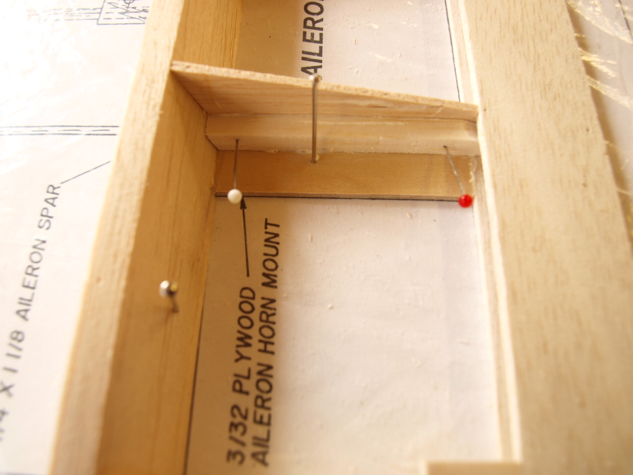 |
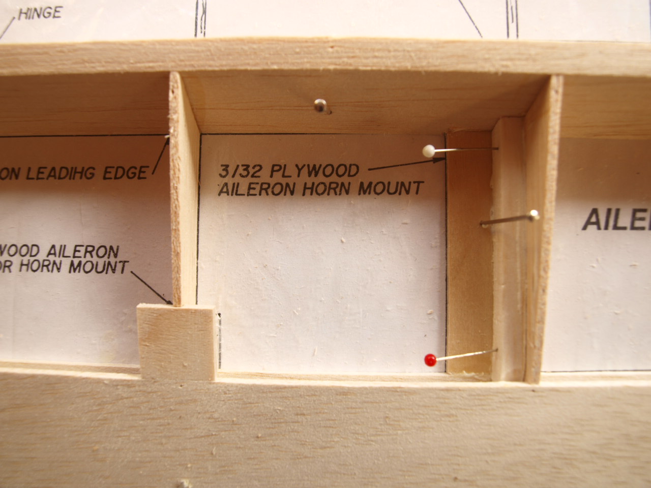 note also Aileron connection rod mount this time placed on top of aileron and not bottom as was the chase when upper wing was constructed |
Once these processes had been carried out the wings where removed from the board and made ready for joining to the centre section. this is carried out as the top wing but instead of having a dihedral of 1 3/8 as the top wing dihedral the lower is set at 1 9/16 . The other differences are that the centre section for the lower wing will be completely sheeted top and bottom and therefore the W5 ribs that are used in this section have to be packed up from the building board by 3/32 to allow for installation of this sheeting later on in the construction progress.
 |
 |
 |
note in this picture that the ply wing
mounting blocks have also been glued into position |
Once the ribs have been located into position the front and rear Main spars are glued into place as per the method used in the top wing see below
 |
 |
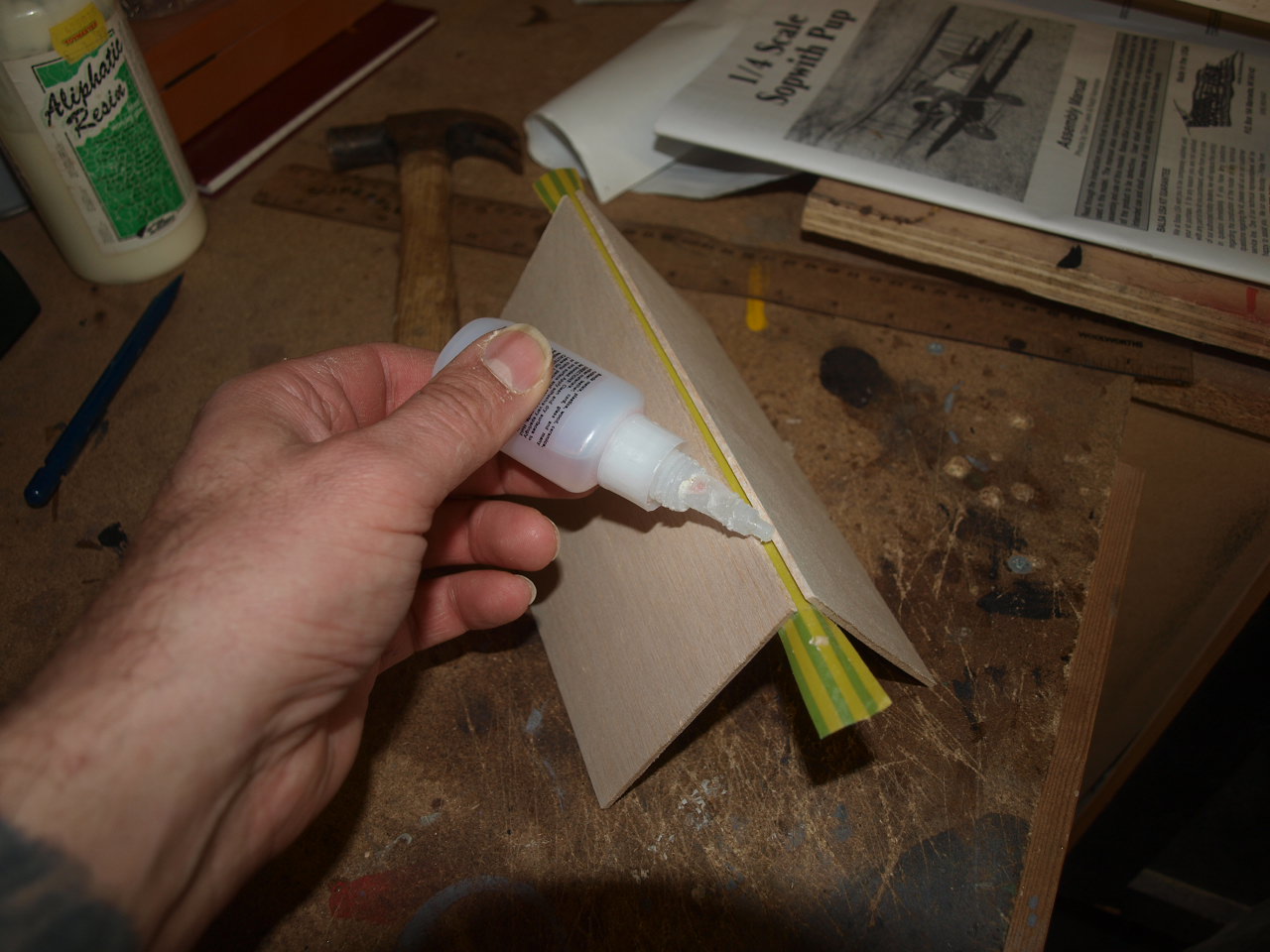
With these both in place the next job is to glue into place both the trailing edge top sheet and the leading edge. These operation where carried out in the same manner as the top wing.
Next the top sheeting is cut and placed into position. It is required that the mid section sheeting has to be but joined together. The best way I have found of doing this and achieving a near seamless joint is to place a strip of cellotape over lapping the edge of one edge to be joined and the lay this flat on the building board and then offering up the other edge to be joined to the first pressing down once in position so that the overlapping portion of the tape affixes to this sheet. then I lift this of the board and fold back the two sections. Then I run super glue along on edge and the fold the two sections back together to create the weld. See pictures below.
 |
 |
 |
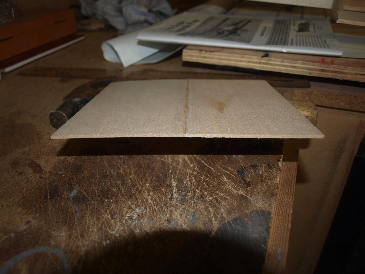 |
Once completed this sheet is cut to size and glued into place along with the other pieces required to finish of the top sheeting of the centre section . The lower portion will be added later as the structure needs to remain open until final assembly.
 |
 |
Stabiliser Construction
Rudder construction
Fuselage Page
Struts & Control Linkages
Final Construction
Engine installation
Aileron installation
Sopwith Page
Home page