LANDING GEAR
The landing gear assembly provided on this model is not scale to the aircraft we are basing this kit on , therefore we intend to rework it to be more scale like in appearance.
We have already tried to modify the pre-bent landing gear wire supplied in the kit and all I can say on that is, we have only managed to produce a very poor representation to date. This turned out to embarrassing to show any pictures of on this site.
In trying to adapt
what was supplied in the kit, has made me so frustrated that I have seriously considered
giving up on the entire build of this model.
My partner in crime, although sharing the same frustrations is
made of sterner stuff and has convinced me that we will be able to come up with
a satisfactory solution to the problems we are currently encountering with this part
of the build.
This kit lends itself to a very good representation of the full-size aircraft and for the life of me I can't understand why there was not more attention given to what is a major feature on this aircraft, by the manufacture of this kit.
Keep an eye on this page to see if I can regain MY interest in this part of the models build.
A clean Start
Having turned my attention to more enjoyable aspects of this kit, (scale detailing) has rejuvenated the passion I had had to build this model.
So a call was made to my partner in crime and discussions held with regards the best way to approach the engineering of an undercarriage frame that would allow us to fabricate a scale wooden covering as per the full size.
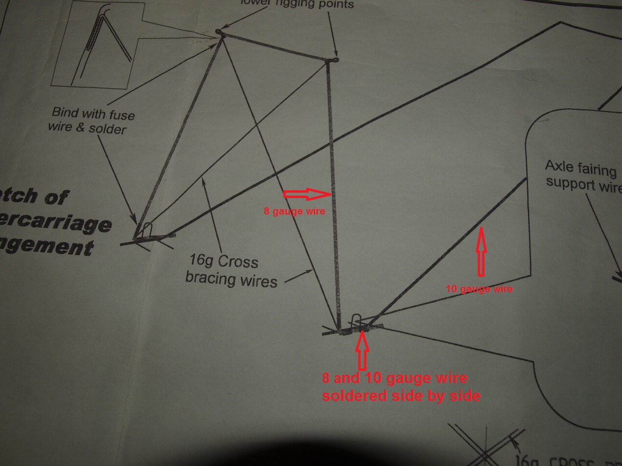
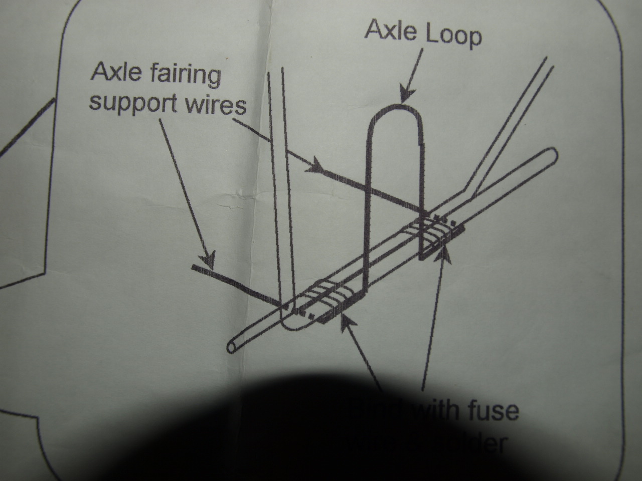
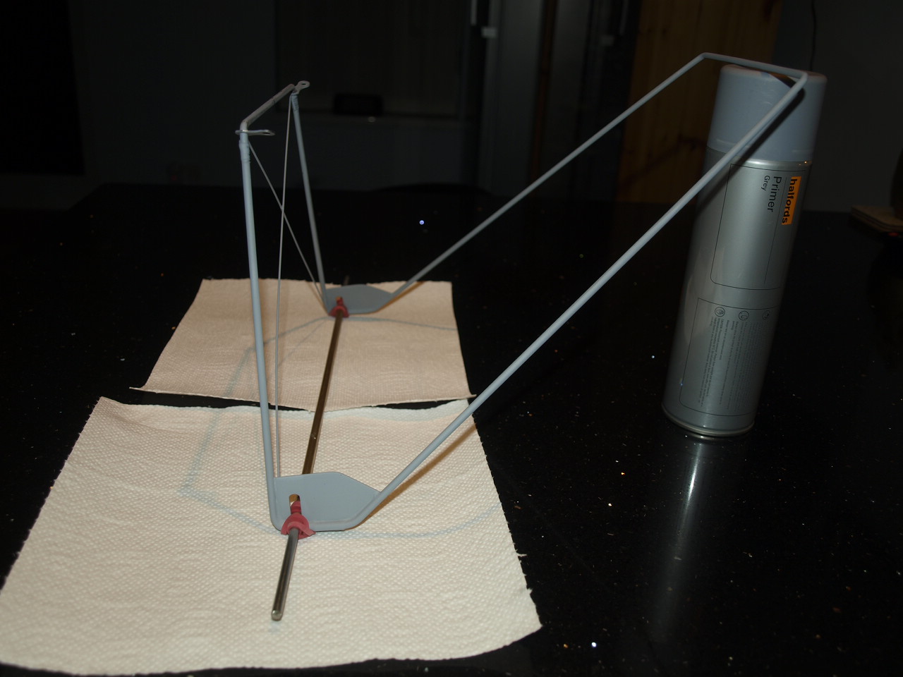
In the first pictures below, they show the kits intended plan make up of the undercarriage.
The plan uses 8 Gauge for the front support wire and 10 Gauge for the rear support wire, with the two coming together side by side, as can be seen by the second picture below. This is how we originally soldered the parts together. But with all the binding wire needed to hold everything together, this made a very thick joint. This would mean that once the wooden fairing laminations where installed, the width of these around the wire would be a least 3/4 inch thick and apart from not looking very scale posed over problems when fitting the main axle, as we want to use bungee cord as per full size aircraft.
|
|
|
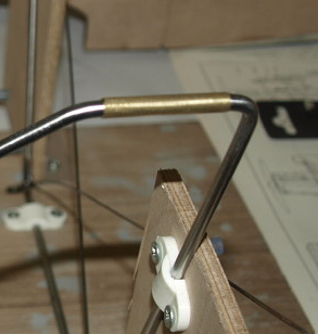
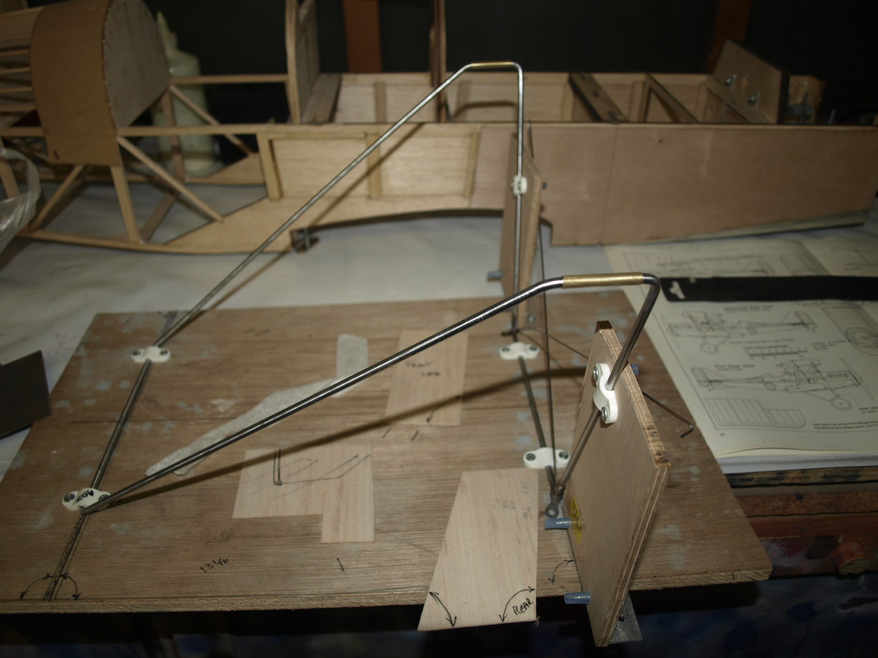
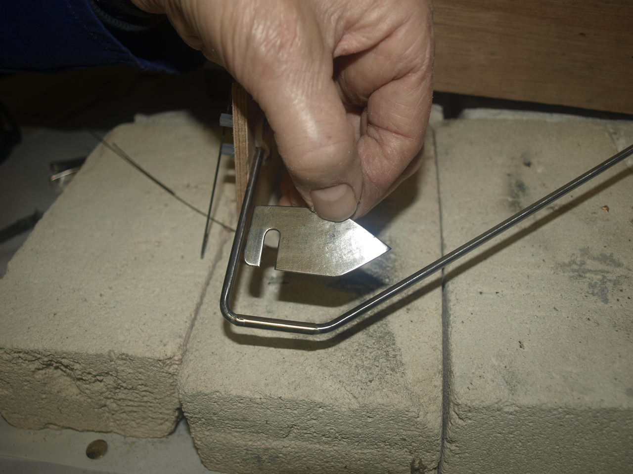
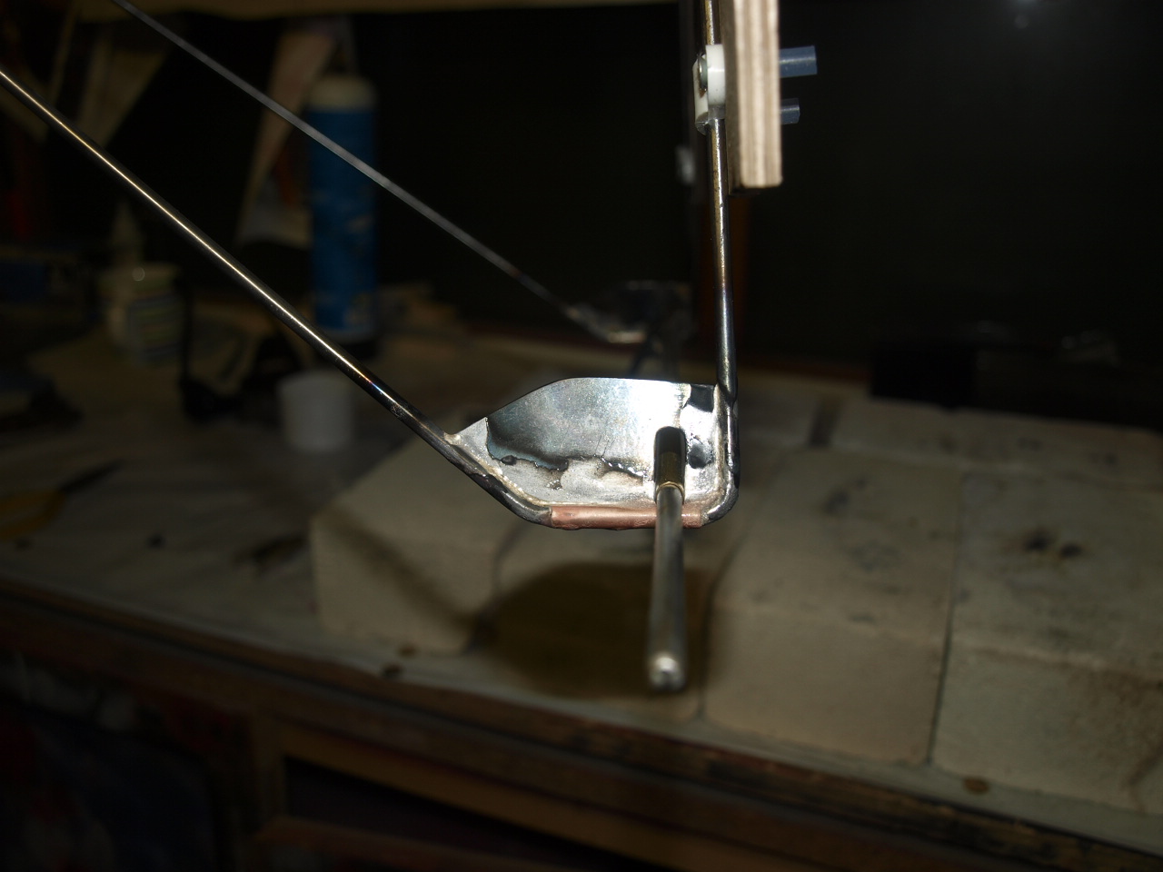
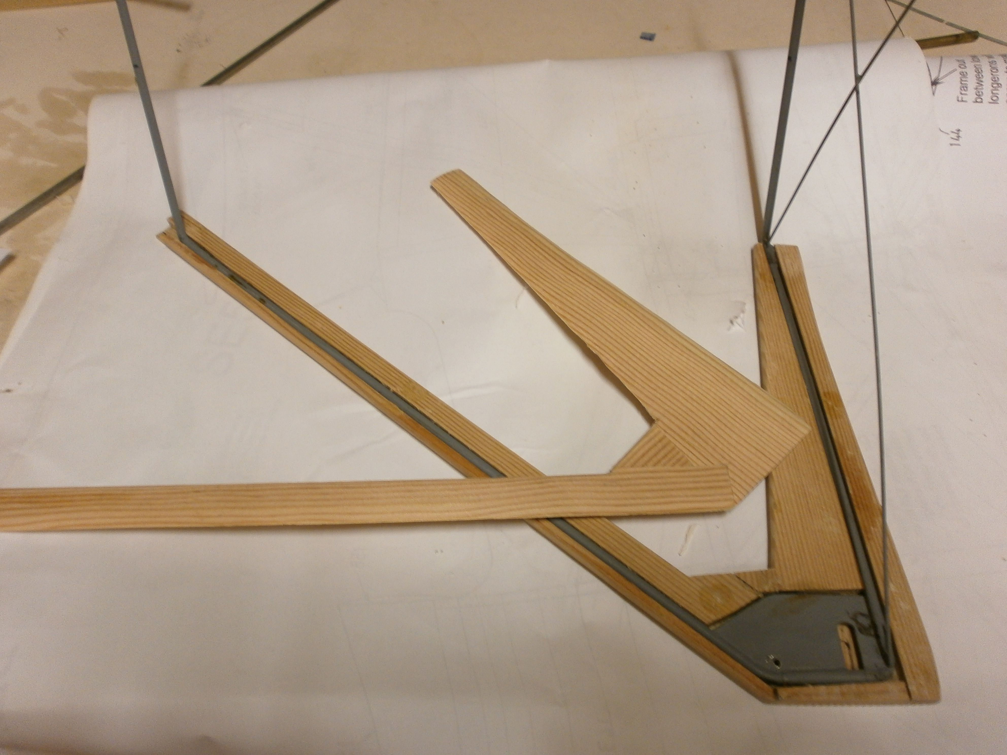
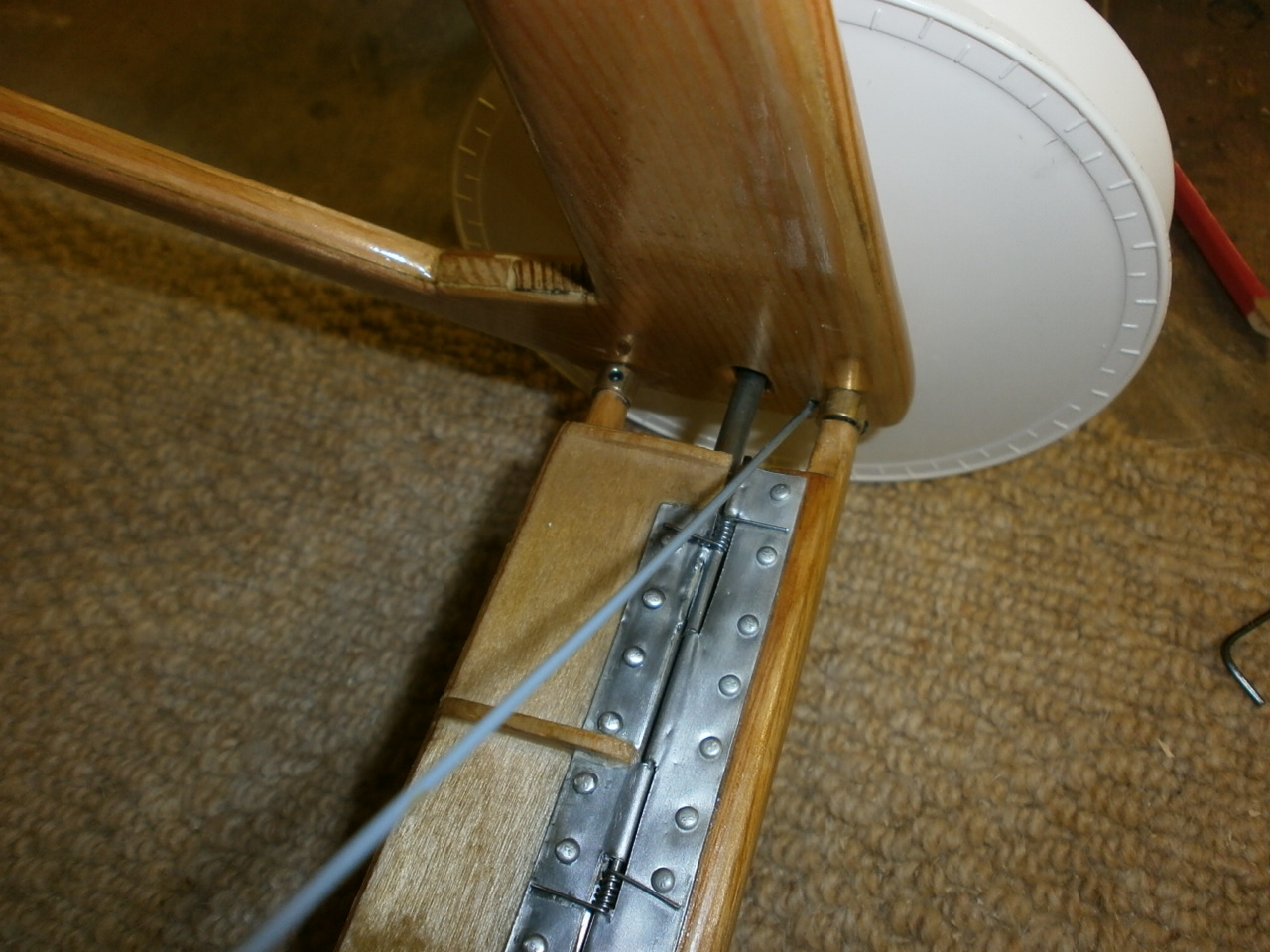
So after much debate we came up with a solution that would get over this problem. Instead of using 10 gauge at the rear, we would use 8 gauge wire as per the front. This wire was bent exactly as the 10 gauge but instead of sitting side by side as previously, both the 8 gauge wires of the separate sections are butted at their ends and are held in situ with brass tube. See first picture below.
The second picture showing the undercarriage setup on the gig used to ensure that everything is square.
 |
 |
The next task was to make up the axle stops. Again we decided to ignore the method used on the plans, instead deciding to use 1.5mm steel plate, which will eventually be hidden by the wood laminations. Choosing this approach will also add improved structural integrity to our modification to that of the plans. (See Picture 1 below)
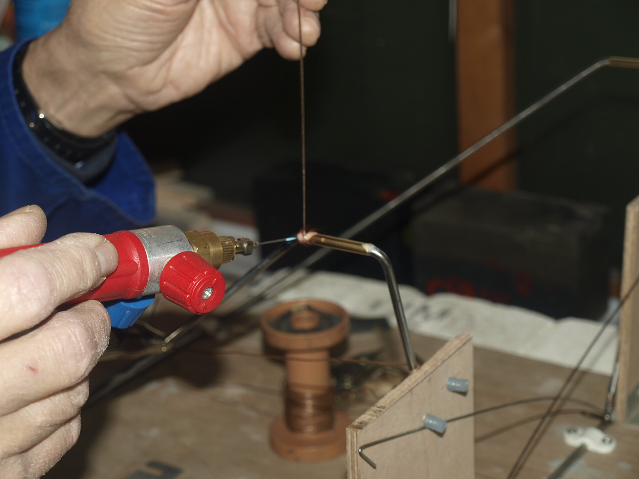
Before these plates are put into position the brass tubing used to locate and hold the two wire sections into position are silver soldered into place ensuring that the solder runs right through the joint. (pic 2)
 |
 |
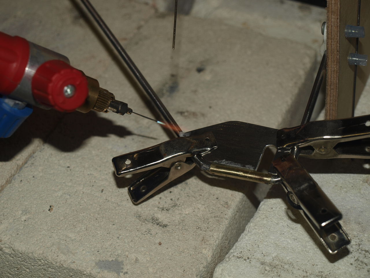
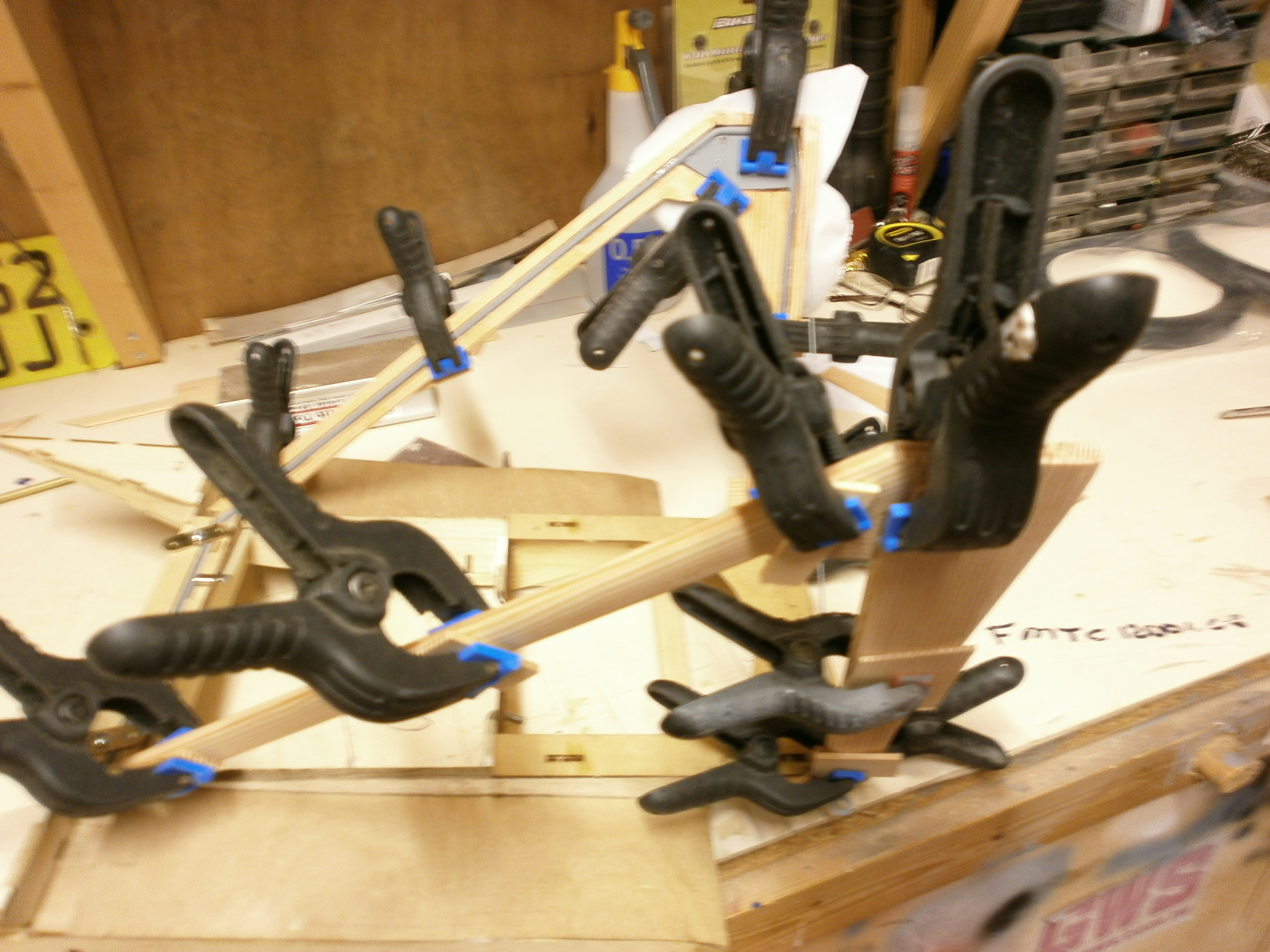
Once cool this joint is cleaned up and the steel plate clamped into position. Once happy with the positioning of the plate it is tacked at each end to hold it firmly into place. (pic 1 below) Now the clamps can be removed and the plate silver soldered in it's final position. (pic 2 and 3 below)
 |
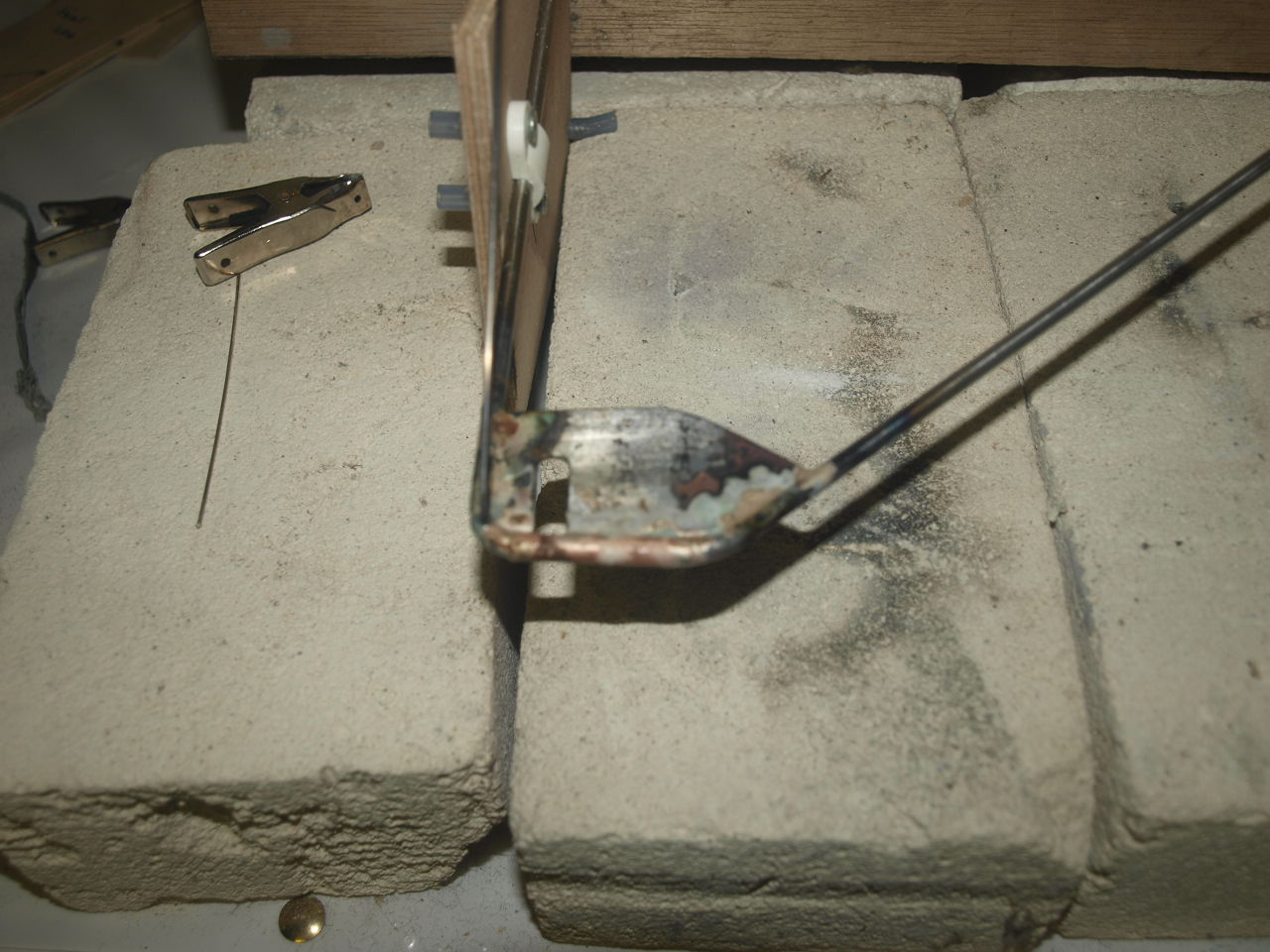 |
 NOTE: AXLE LOCATED THROUGH |
 Under carriage frame all cleaned up and undercoated, ready to receive wooden laminations |
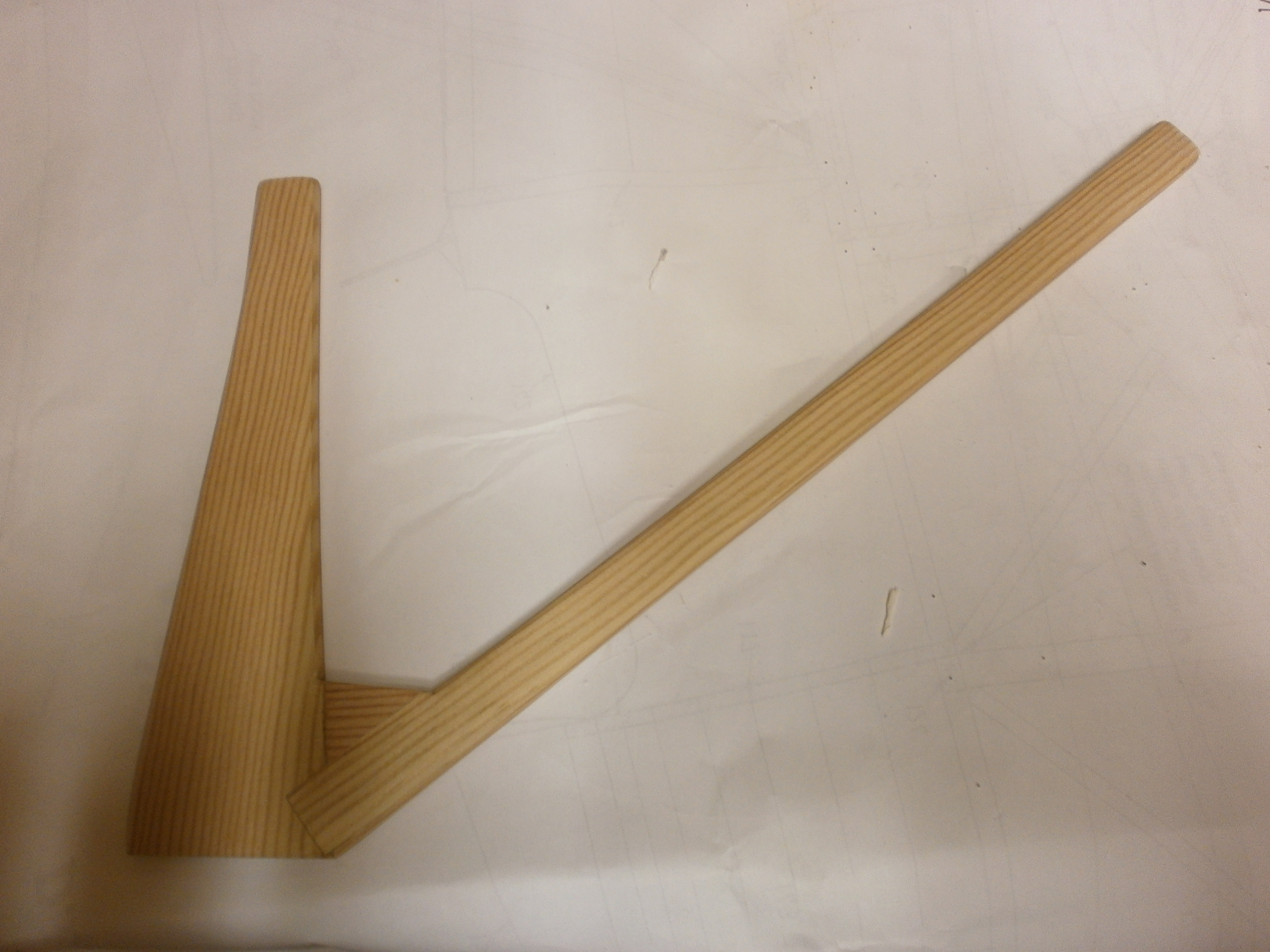
Next the wooden leg structures
are made up for each side. The wood used for this is Spruce.
For the purist's out there this is not exactly to scale, I know.
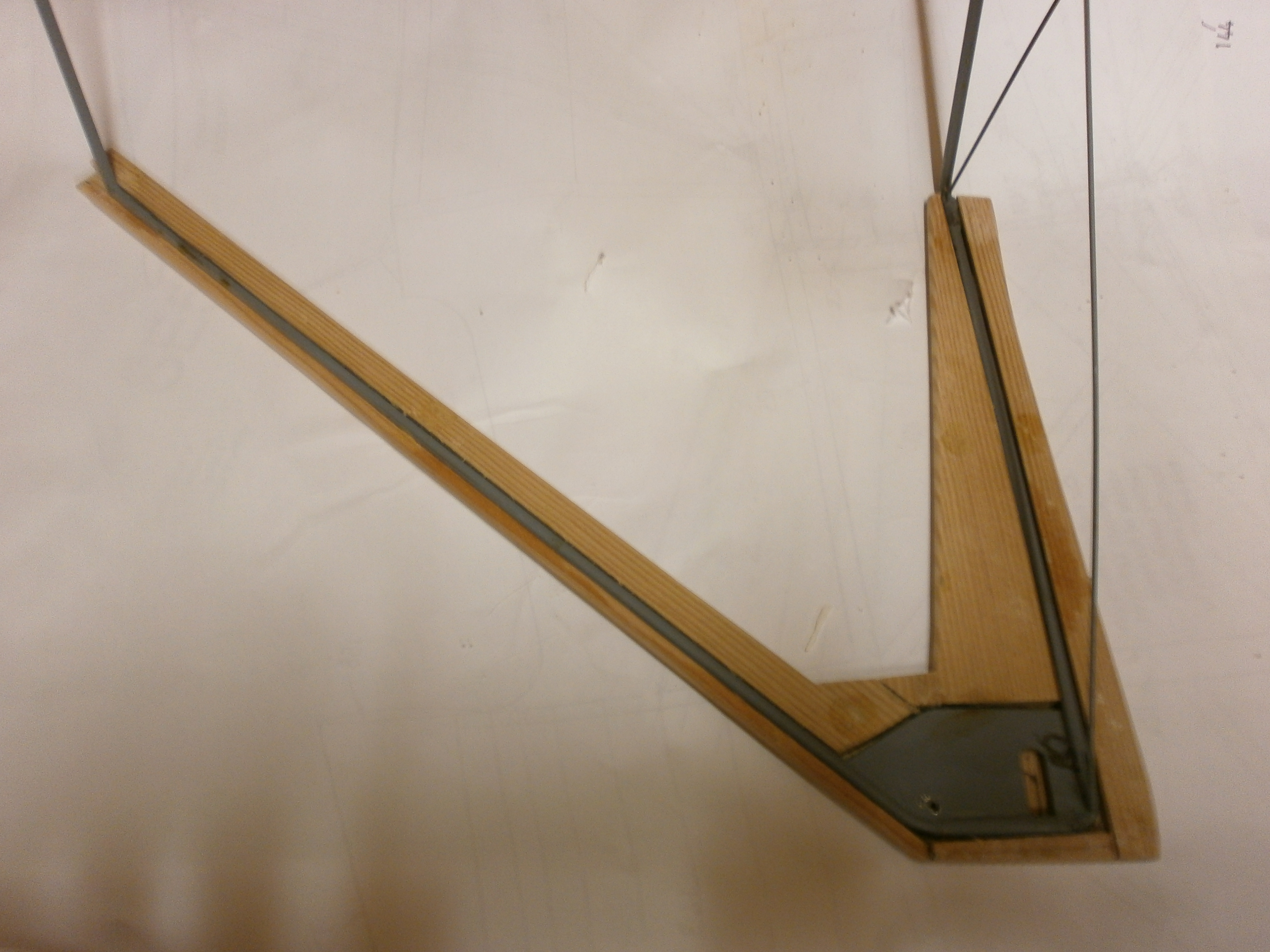
The construction of these parts as can be seen in the pictures below, is by lamination so as to disguise the metal frame.
 |
 |
 |
 |
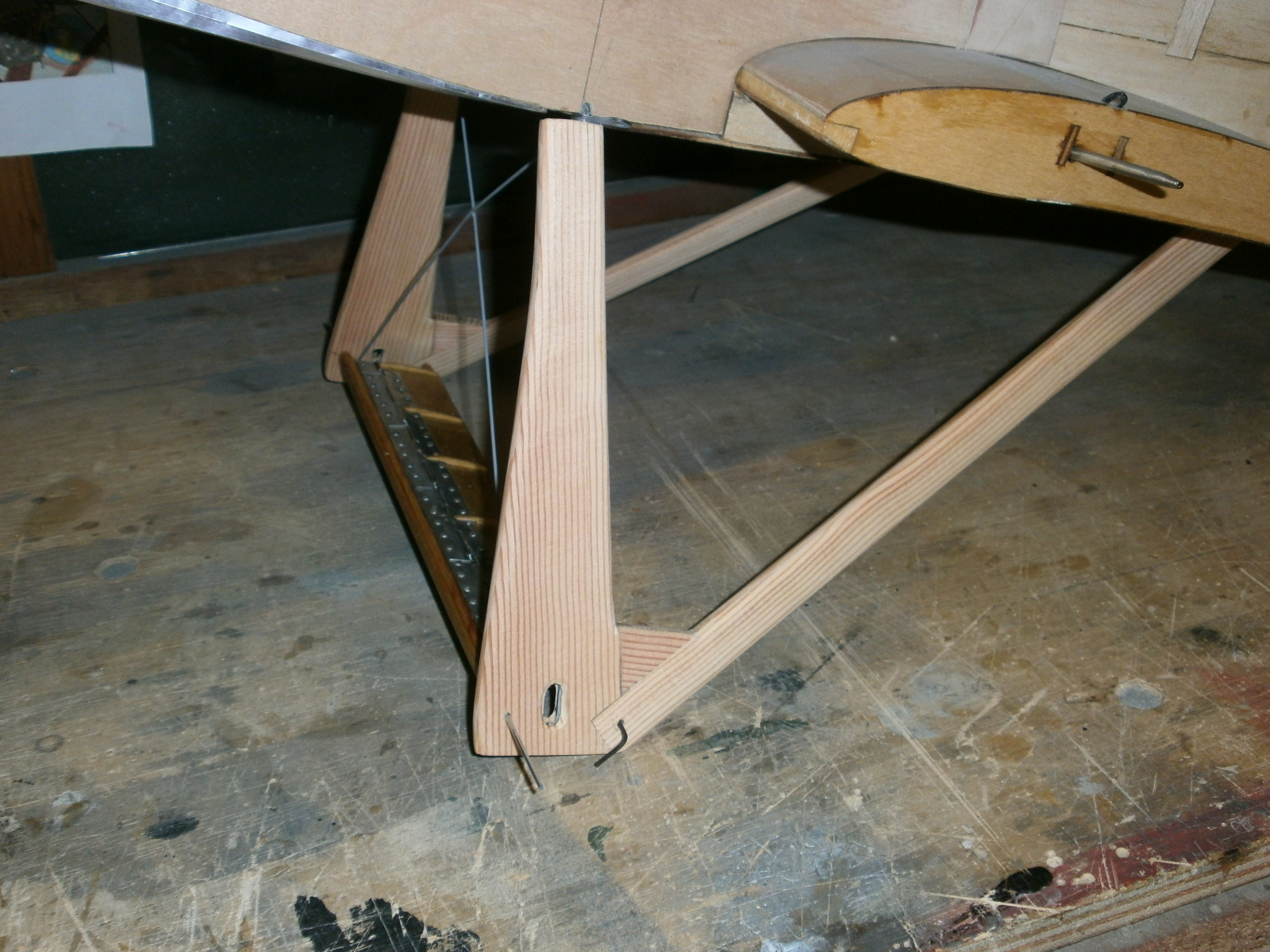
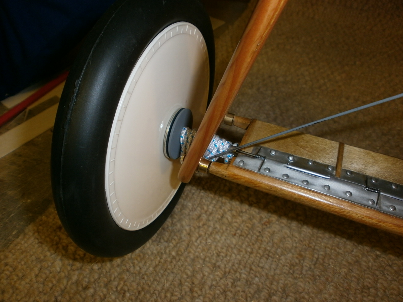
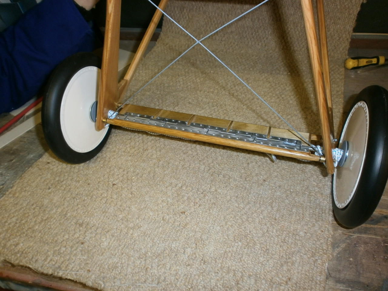
The next picture below shows the assembly now in place on the wing centre section, although it still needs to be sanded to final shape and lacquered.
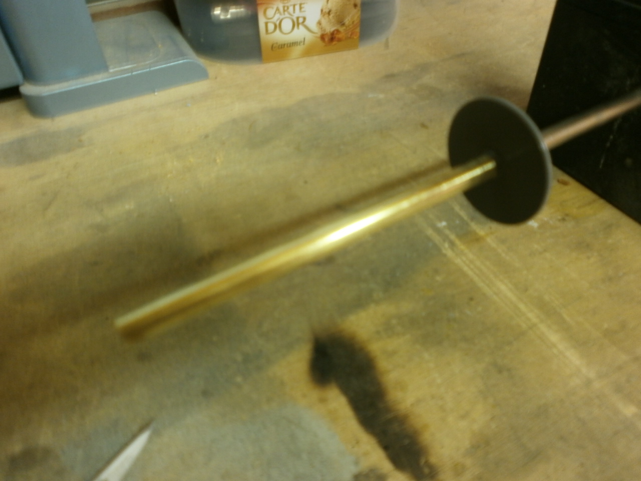
Picture 2 below shows the brass axle with a pot washer silver soldered on the end. This will slide over the piano wire axle that runs through the winglet and will be soldered into place. The wheel then fits over this with the pot washer acting as a stop to prevent the wheel from coming into contact with the main undercarriage and scale bungee suspension cord.
 |
 |
The following pictures below
show the winglet installed along with the axle running through it.
The winglet is held into position by four metal pushrods (2mm) which have a
nut epoxied onto the threaded end. These are inserted through the
undercarriage sides from the outside and then locate into the winglet beams.
All are held in place by brass collets to stop them working their way out
during normal fight conditions See first picture below
 |
 |
The next two pictures show the bungee rapped and in place. All that is left to do now is finally solder the outer brass axle to the main piano wire axle and secure the wheels which will be achieved by placing a small washer in front of the hub which in turn is then held in place by a split pin which runs through the brass axle tube (picture of this to follow)
 |
 |
Stabiliser Elevator Build
Fuselage page
Fin & Rudder Build
Wing Build Bottom
Wing Retaining
System
SE5A Full size detail gallery
SE5A Cowl
SE5A Scale detail