SE5A Fuselage Page
This page will follow the building of the SE5A fuselage.
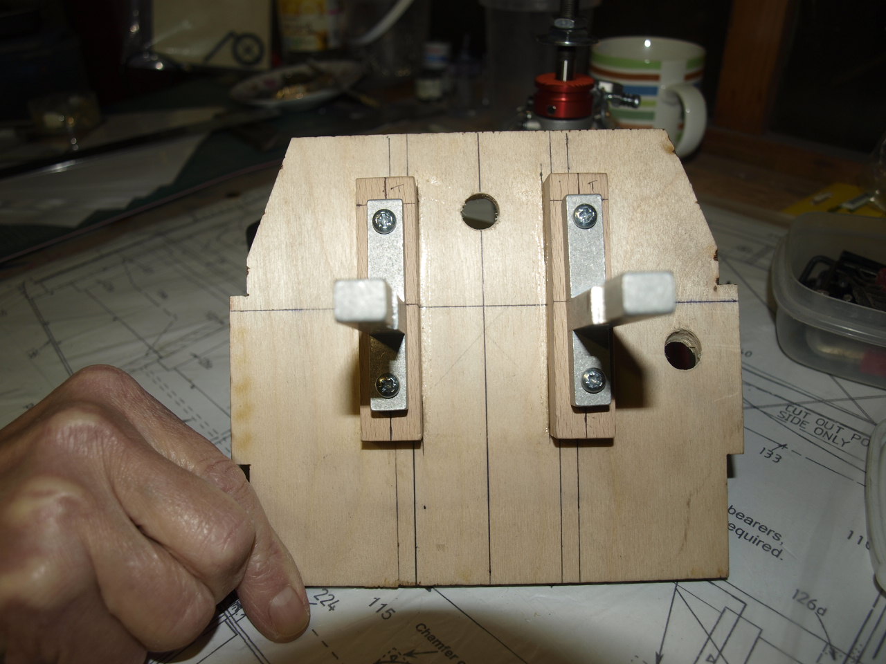
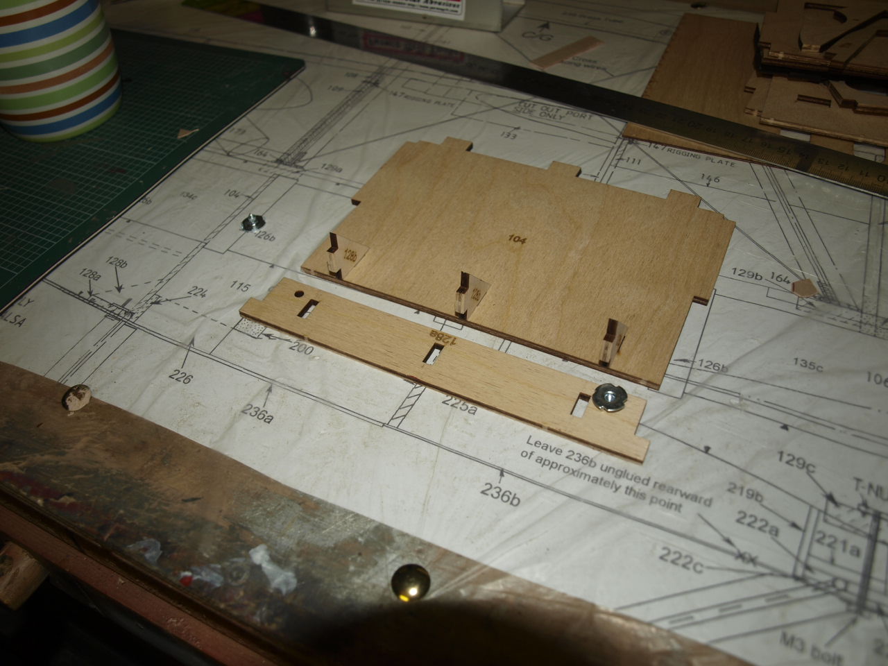
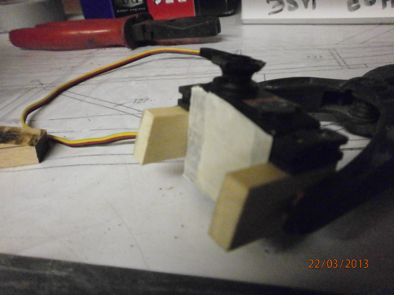
Before construction of the fuselage commences it is advisable to work out the location of where the engine will sit as trying to do this later once the fuselage has been constructed will prove very difficult and may well see the structure damaged when working on trying to install the mounts.
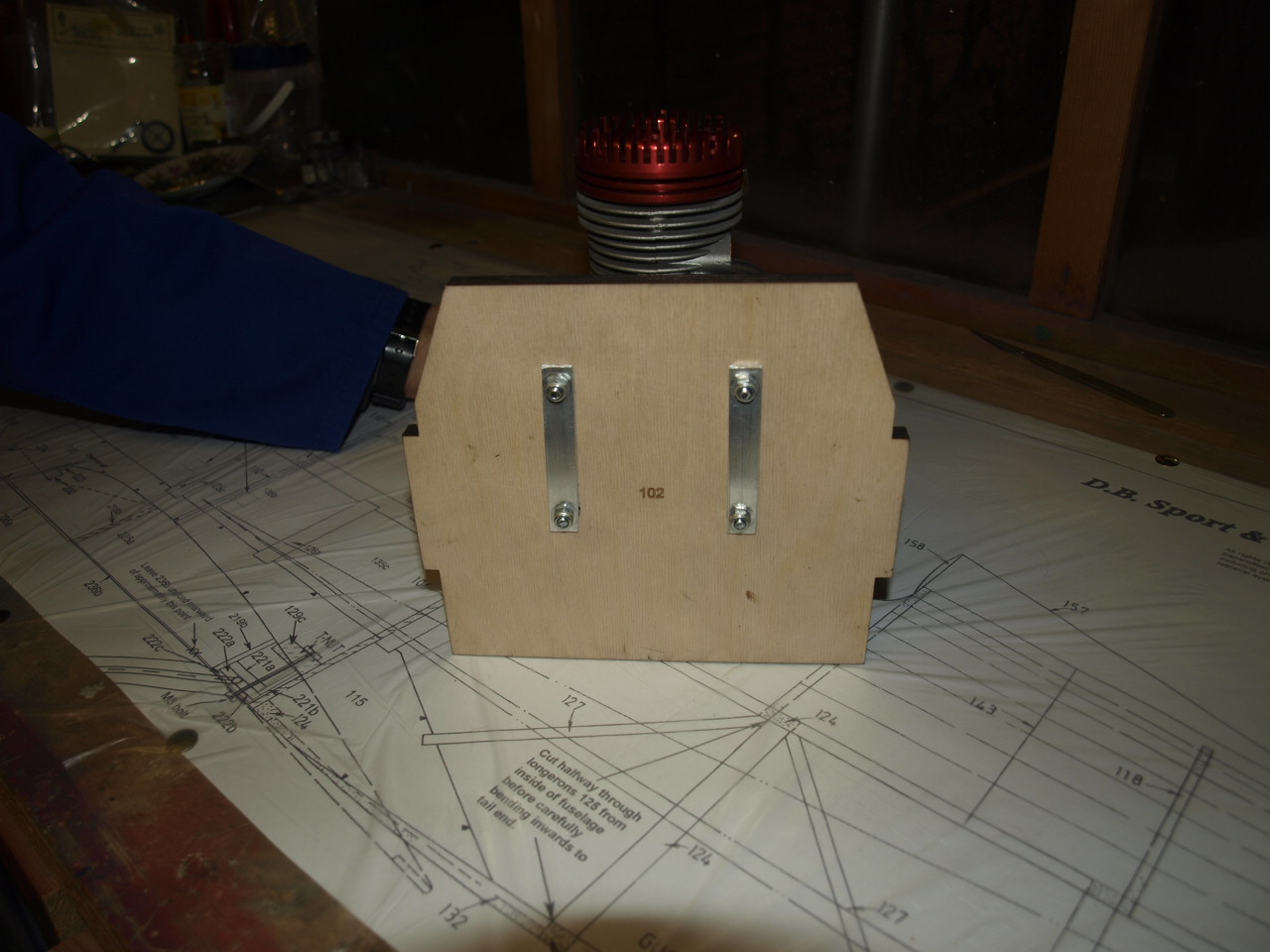
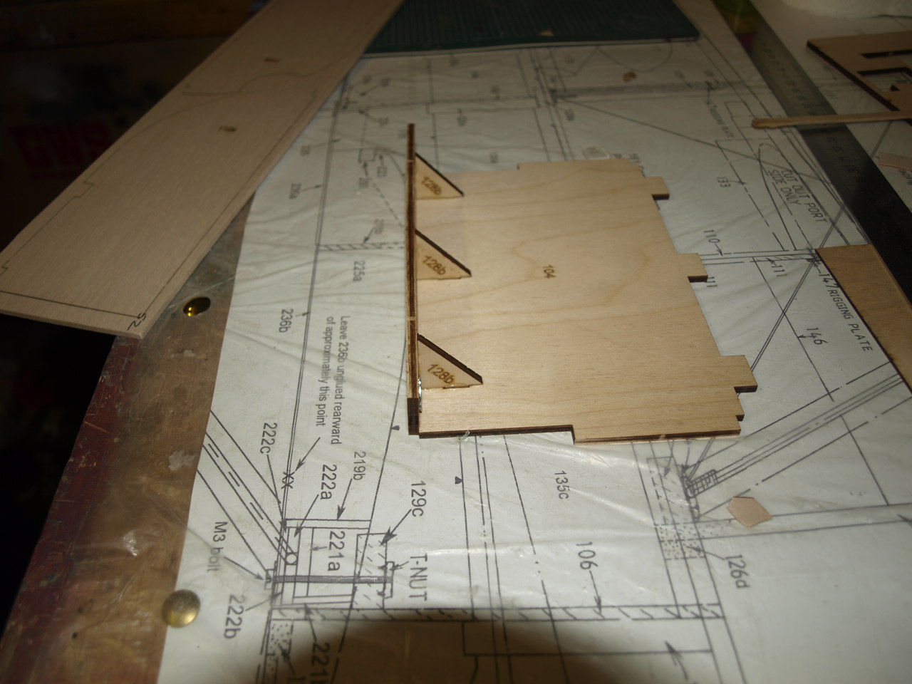
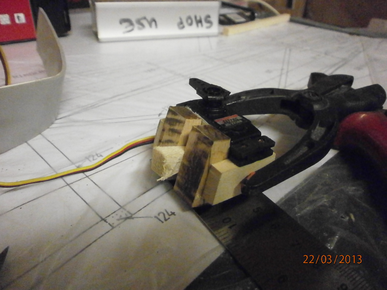
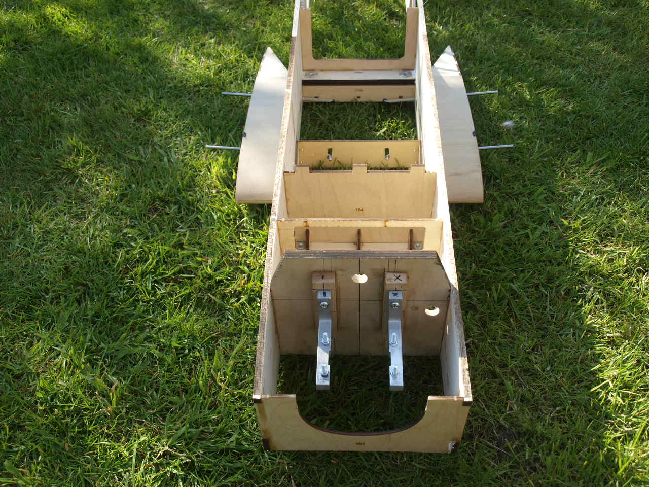
The following three pictures show the mounts in their correct positioning. Note in picture one below we have had to add beech bearers to bring the prop shaft out to it required position 144mm from the back of the firewall. The next picture showing the rear of the firewall and the two brackets we have made up for the nuts to tighten up to.
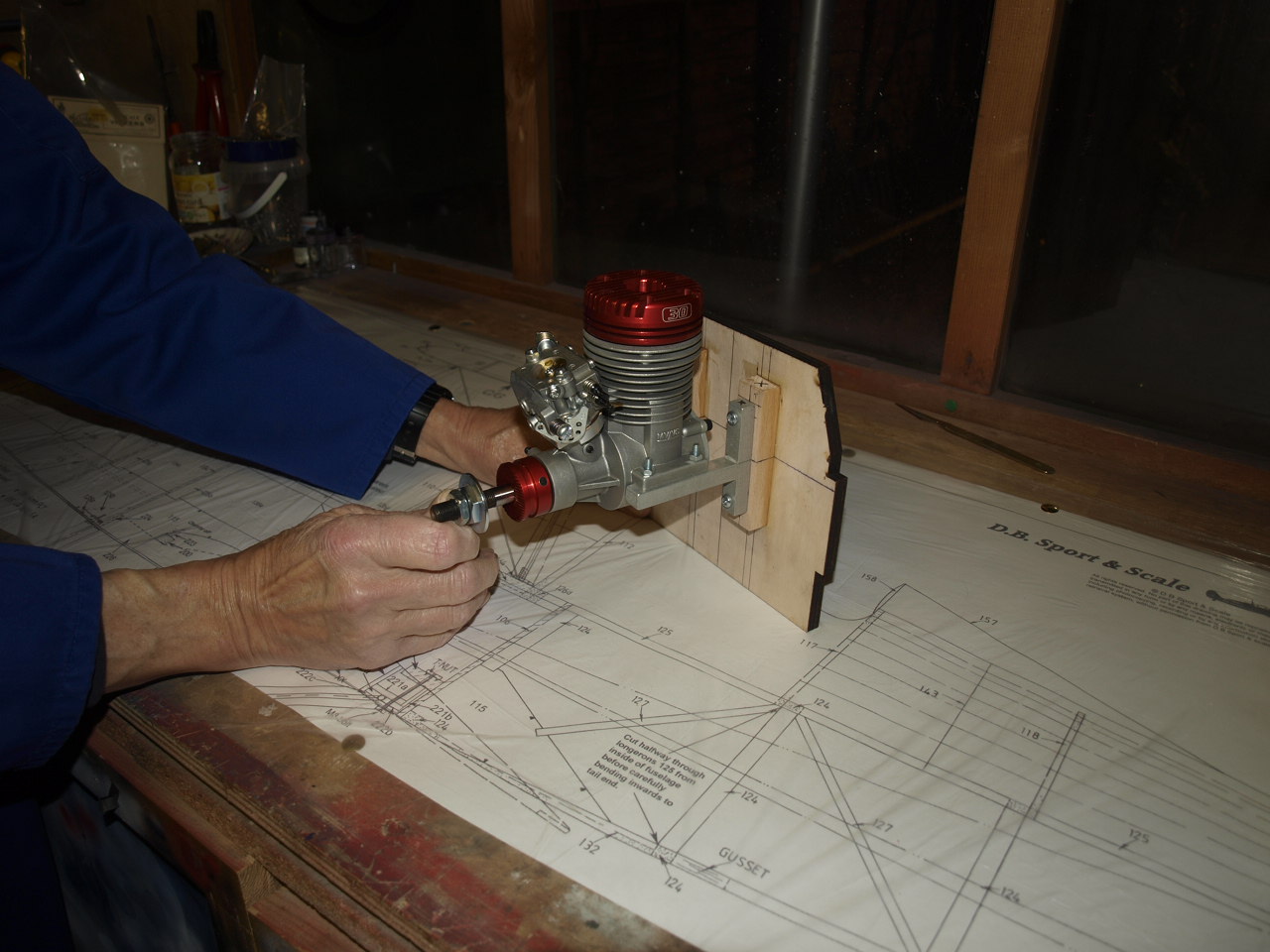
The last of the three pictures showing the engine sitting in its correct positioning. This model needs no side or down thrust introduced
|
|
|
 |
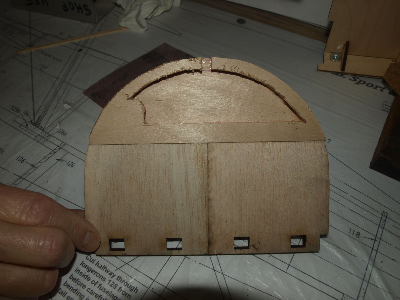
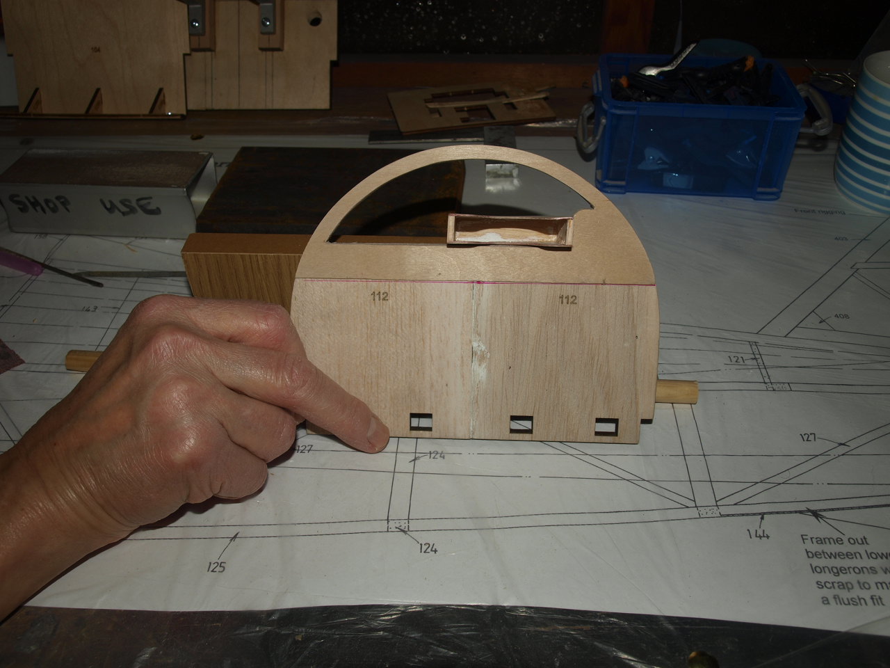
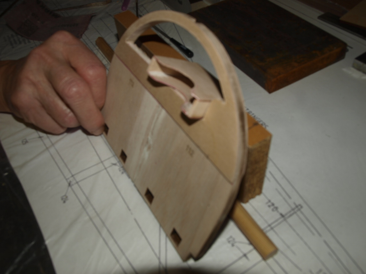
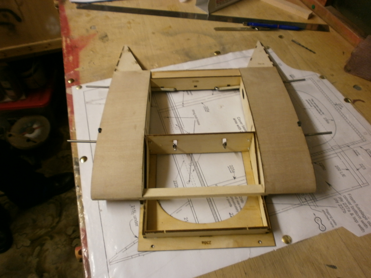
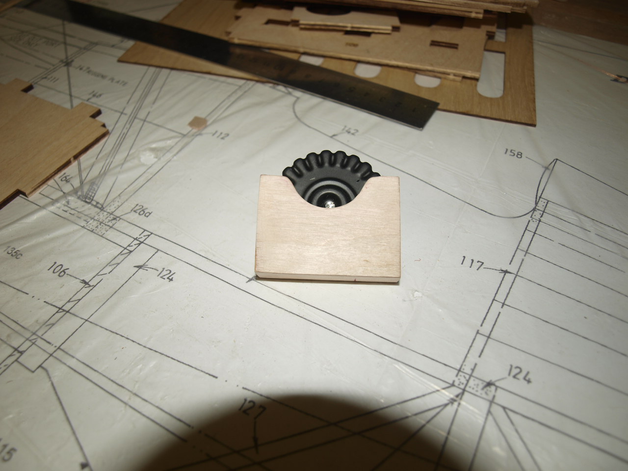 Having looked at the plans and the instructions we have decided to modify one of the formers that sits where the cockpit dash should fit. On the full size aircraft this is opened up and houses on of the Lewis ammo magazines in a box . This picture is my attempt to replicate the box |
The pictures below showing the F2 former parts ready for gluing and glued. the smaller piece has captive nuts that will be used to secure the undercarriage. We will properly beef this up somewhat to accommodate those hard landings that we all make at sometime on the flying field.
 |
 |
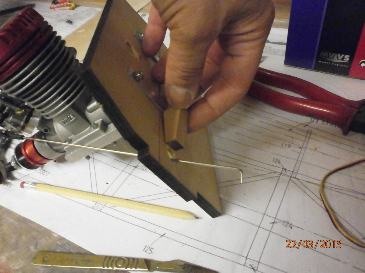
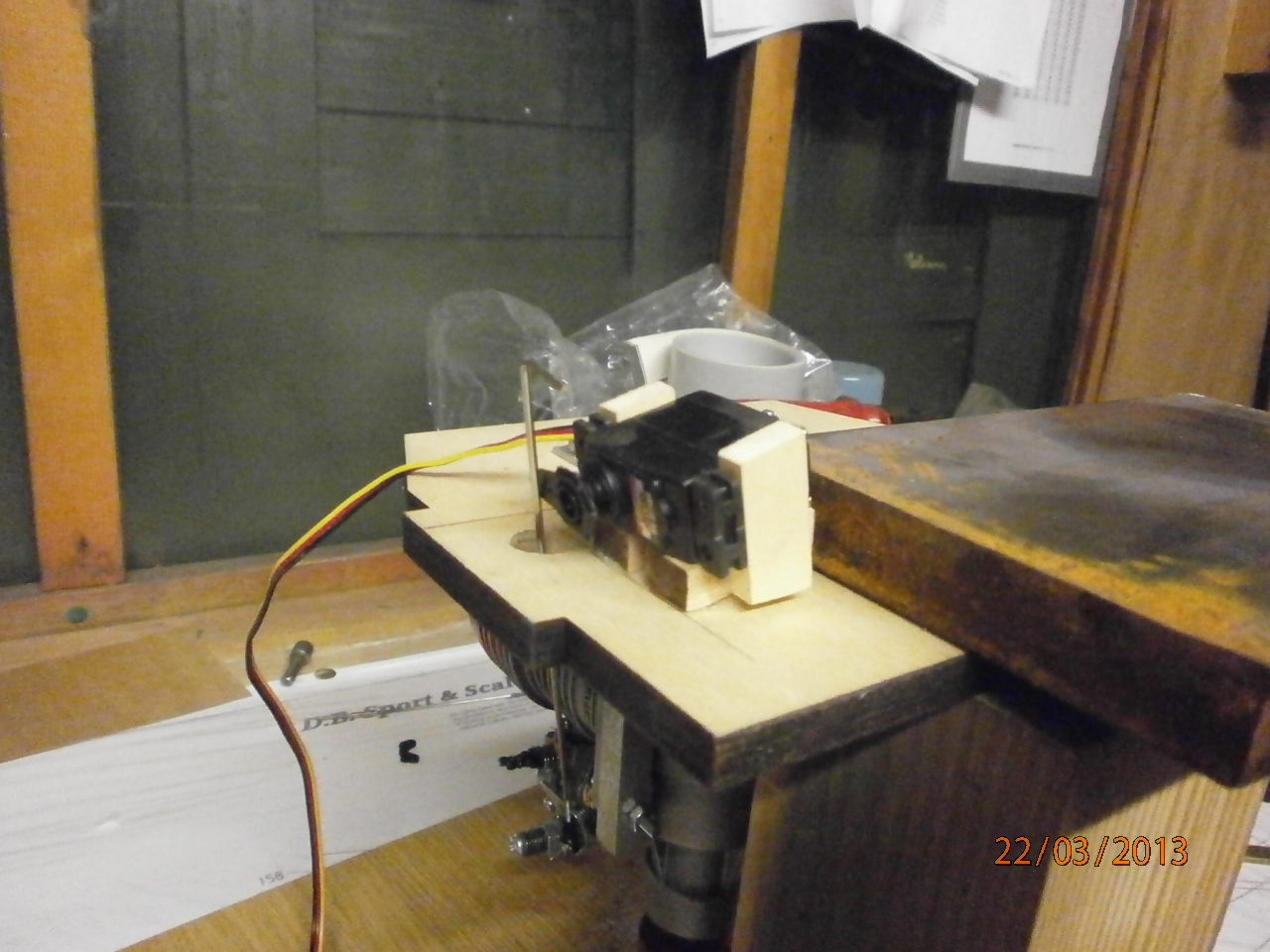
The following pictures showing the throttle linkage set up passing through the firewall to the servo and its mount. Various wooden blocks are made up and angled so that when glued into position and the servo located onto these, the servos control horn aligns exactly with the throttle linkage pushrod
 |
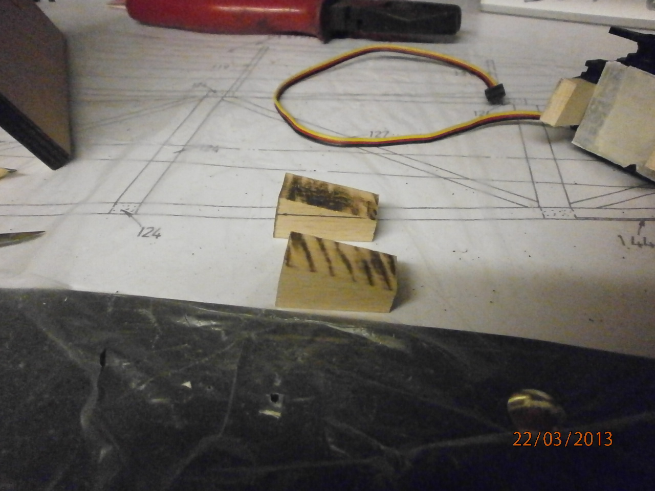 |
Pictures below showing the wooden servo blocks and their construction around the servo ensuring a snug fit.
 |
 |
The completed mount now epoxied into location on the rear of the firewall
 |
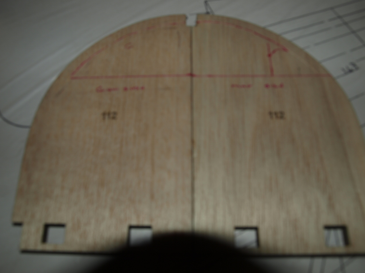
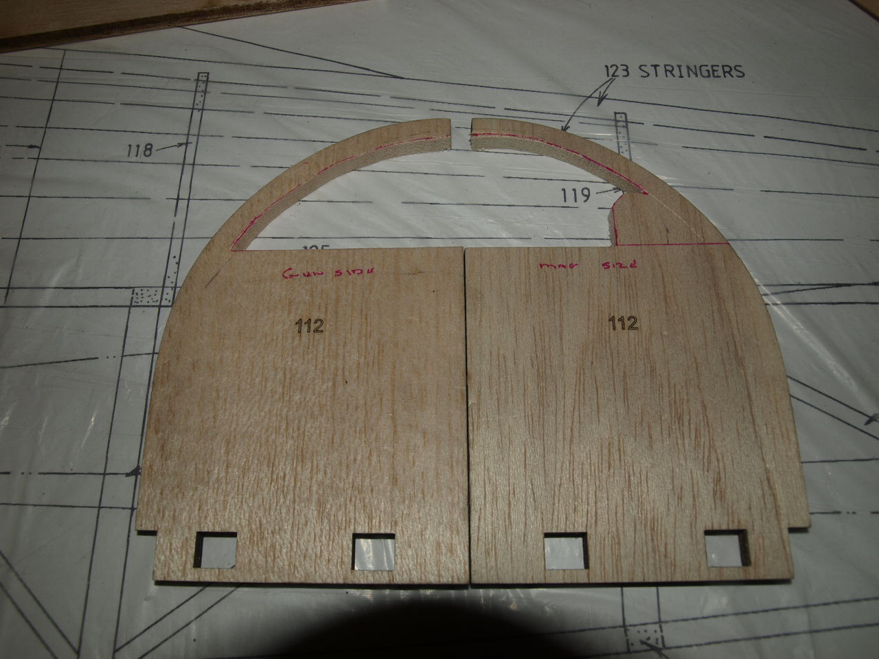
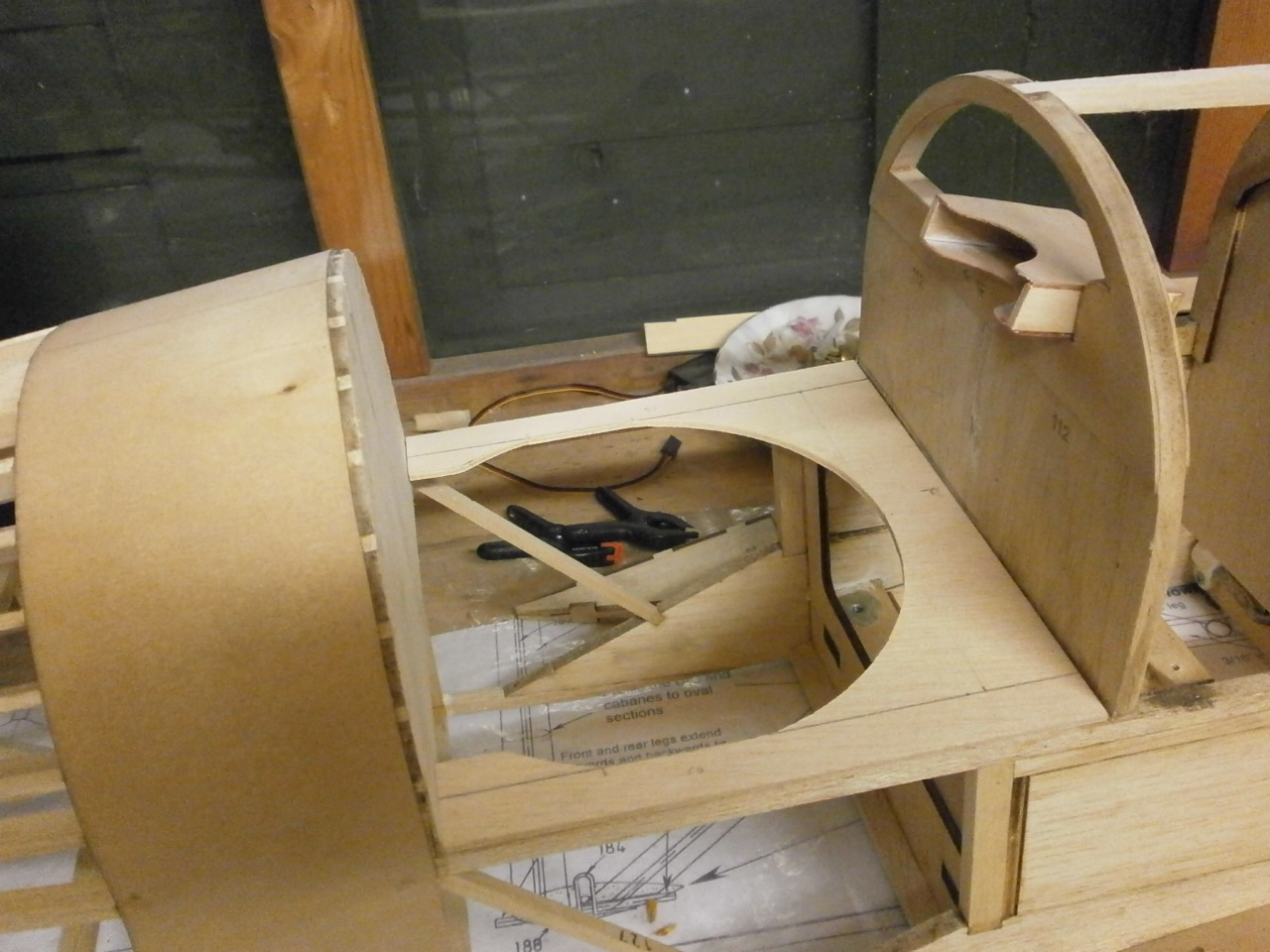
The instructions now tell
you to make up the 112 former. For some reason this former like others in
the kit come in to half's.
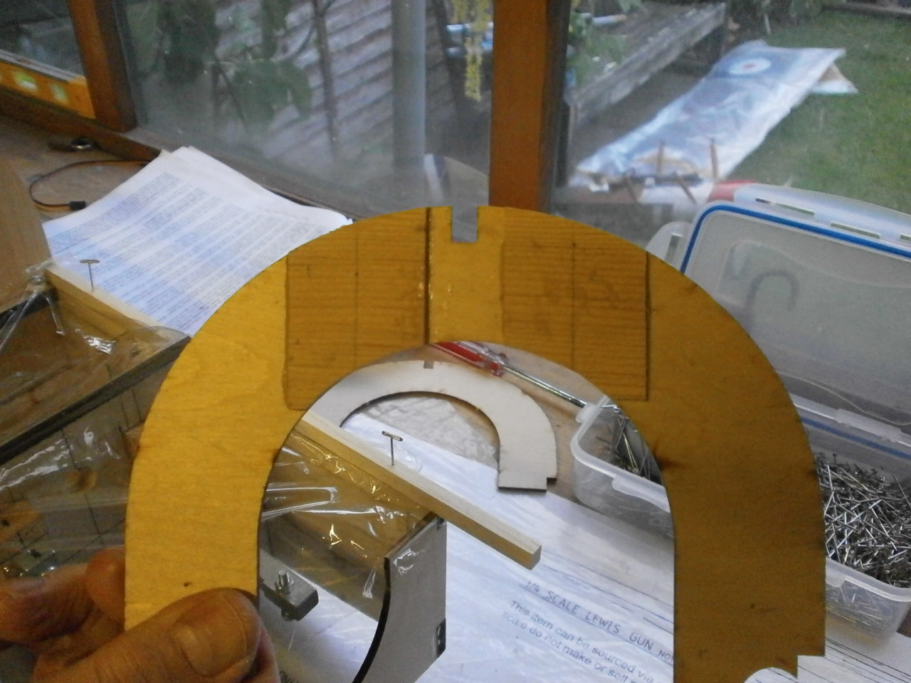
As you can see from the first picture below this former has been cut as a
solid sheet. Once in place this former sits where the cockpit instrument
panel will go.
As we want to achieve as scale a representation as possible, this item requires work to ensure it looks like the one in the picture below.

The following pictures show the process of getting the former cut out to resemble that of the full size. As the project moves on the further scale detail will be added to get this part as scale like as possible
 |
 |
 |
 |
 |
 |
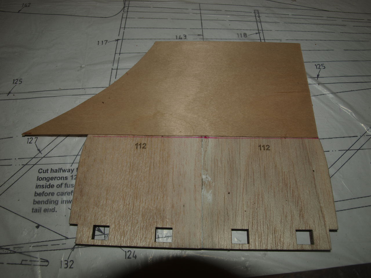
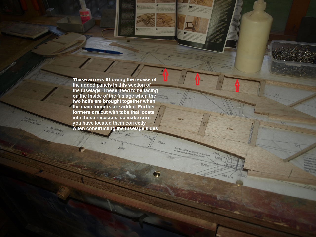
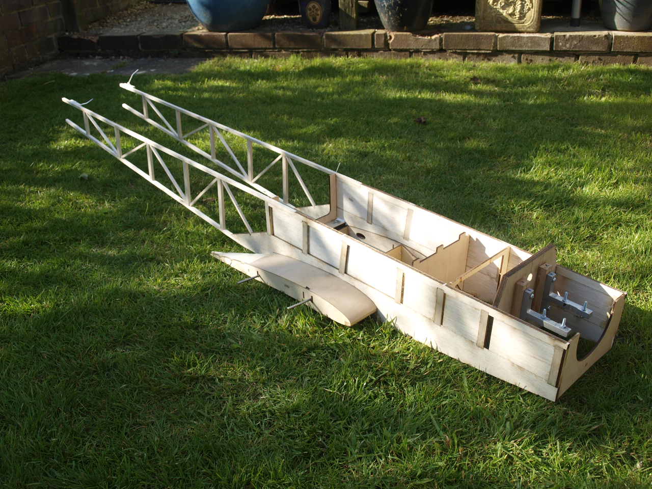
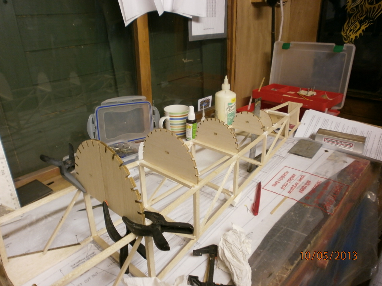
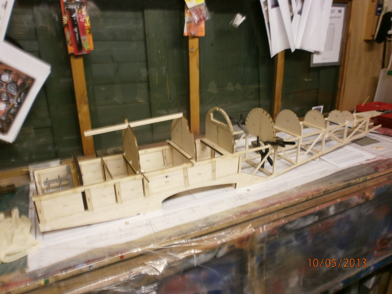
The Fuselage sides are now made up over the plans making sure that you have a pair of handed sides.
 |
 |
Once the two sides are constructed you can then join them both together using the formers provided. These formers have location tabs that fit into the openings left in the fuselage sides during their construction (see larger picture above). It is very much advised that you get someone to help you here as this job is very fiddly for just one person to tackle on their own.
We used the centre bottom wing section made earlier in this build as an aid to ensure that every thing was going to fit correctly prior to gluing up.
Once happy with our dry fit, we proceeded with gluing the formers into their final locations, checking with a square to ensure everything remained true.
 |
 |
This picture showing the now joined Fuselage sitting / located over the bottom wing centre section all nice and square, indicating that the fuselage is accurately squared up.
 |
 |
 |
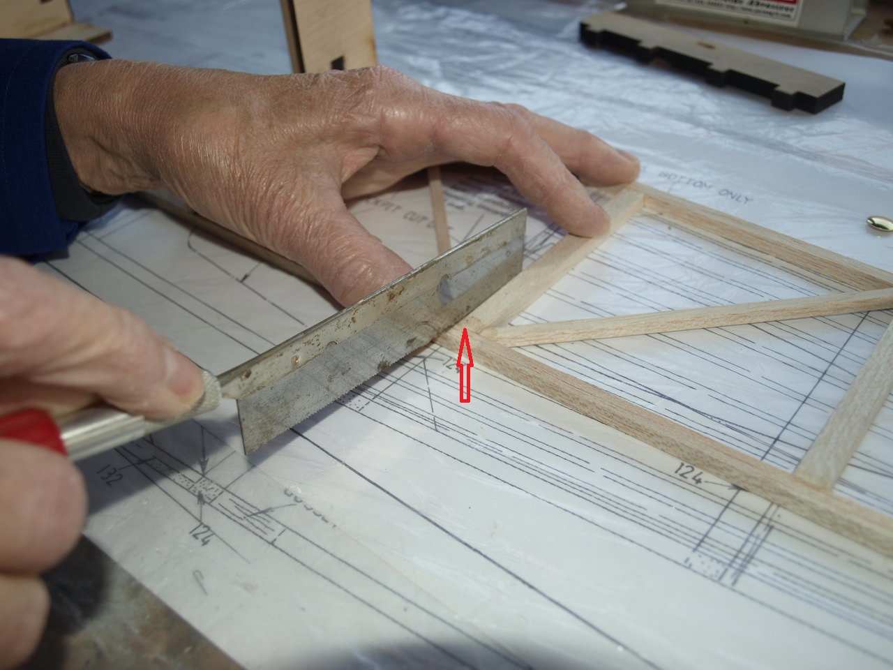
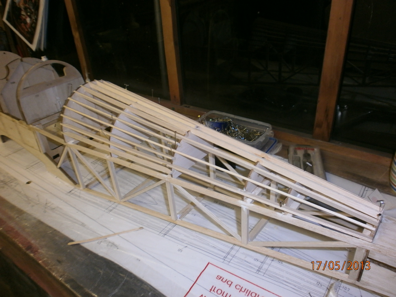
The next job is to add the rear cross formers that bring the rear of the fuselage together. Before this operation is carried out, the instructions tell you to cut halfway through the longerons, as can be seen in the first picture below (arrow marks the spot). These cut areas are then socked to soften the balsa enabling the rear framework to be pulled together without any danger of the cut stringers snapping.
To ensure that the rear fuselage remains true during the above / following procedures it was pined down over the plan view of the plans, and with the aid of set squares each side was aligned to ensure that equal bend was applied ensuring everything remained true to the plan ( picture 2 below)
 |
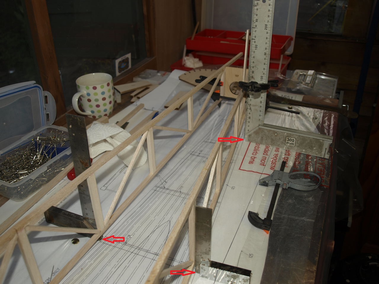 |
Next we add the rear former no. 107 on the plan that brings the two ends together (picture 2 above) again using our square to ensure an accurate fit.
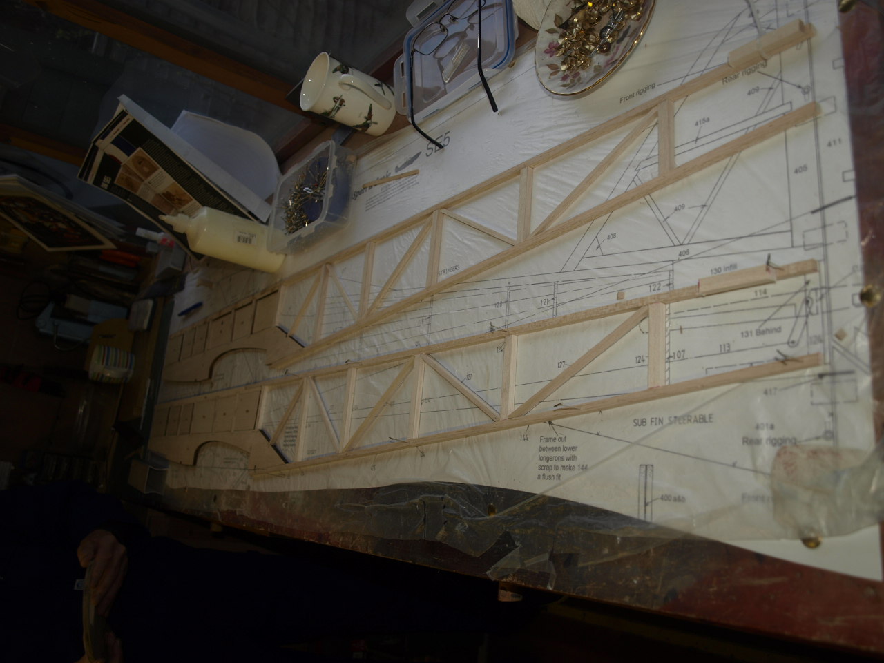
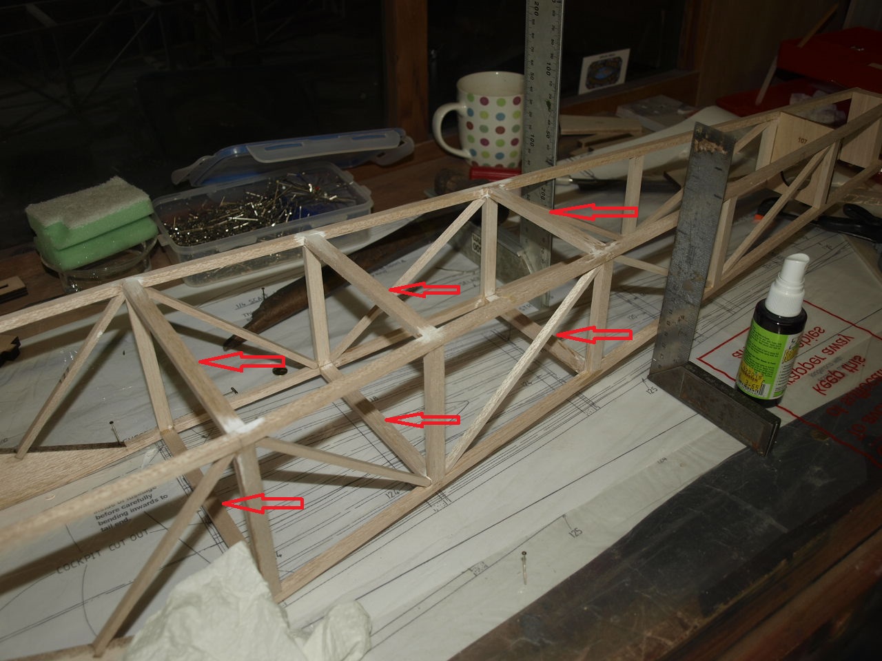
Once this part has dried we then start cutting and gluing into place the upper and lower cross pieces along the rear fuselage length at their required locations as indicated by the plans.
Each pair are glued into place and again the square is used to ensure that everything remains true. Each pair are left to cure before moving on to the next section ( see first picture below) until we reach the end of the fuselage. Now that all the cross pieces are in place we apply a little supper glue to the cut longerons just to ensure structural stability .
The next Job is to install the remaining top formers. This is quite a simple process just following the plans for positioning. See second picture onwards below.
 |
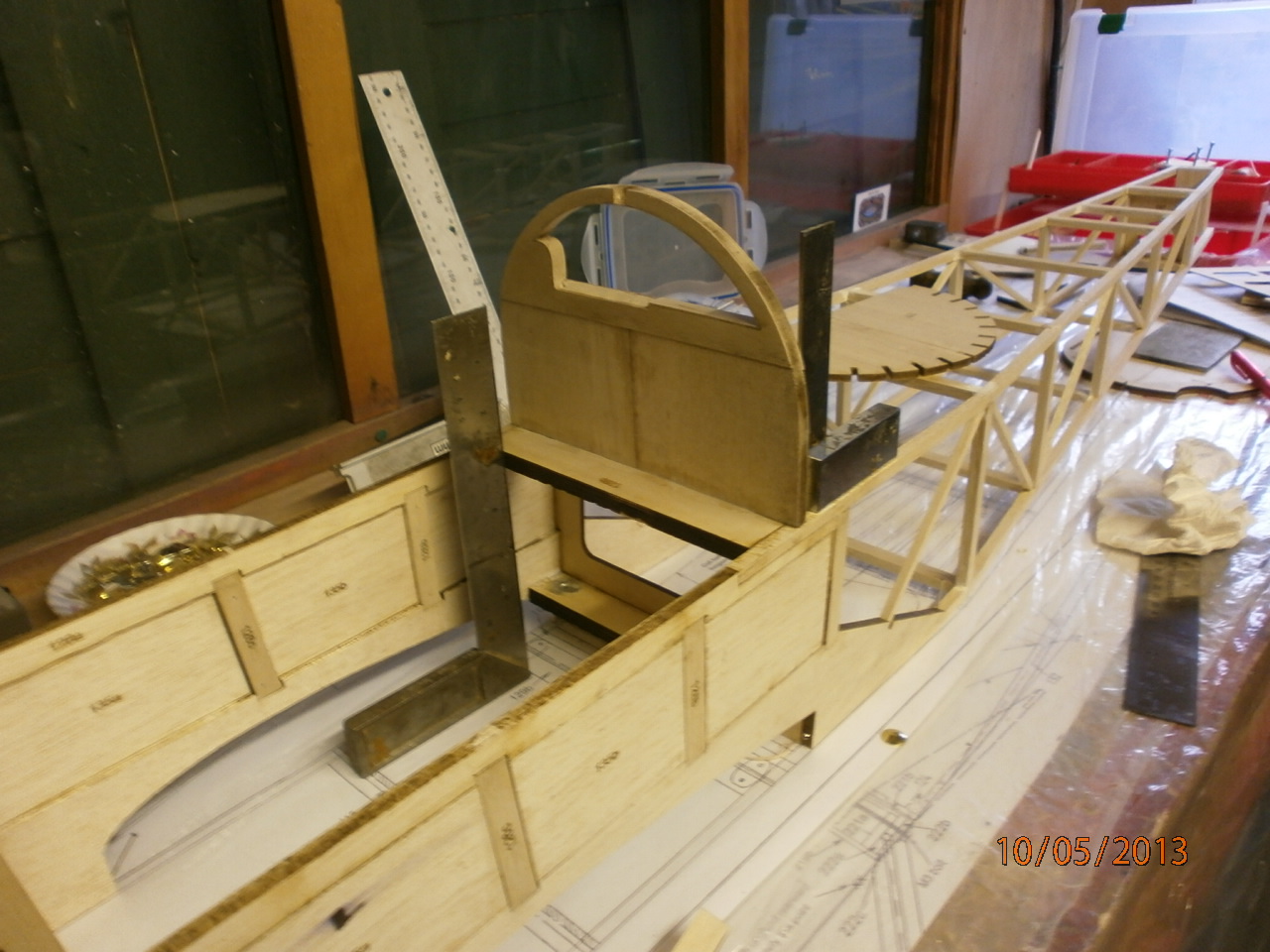 |
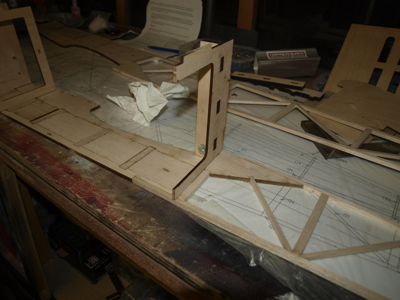
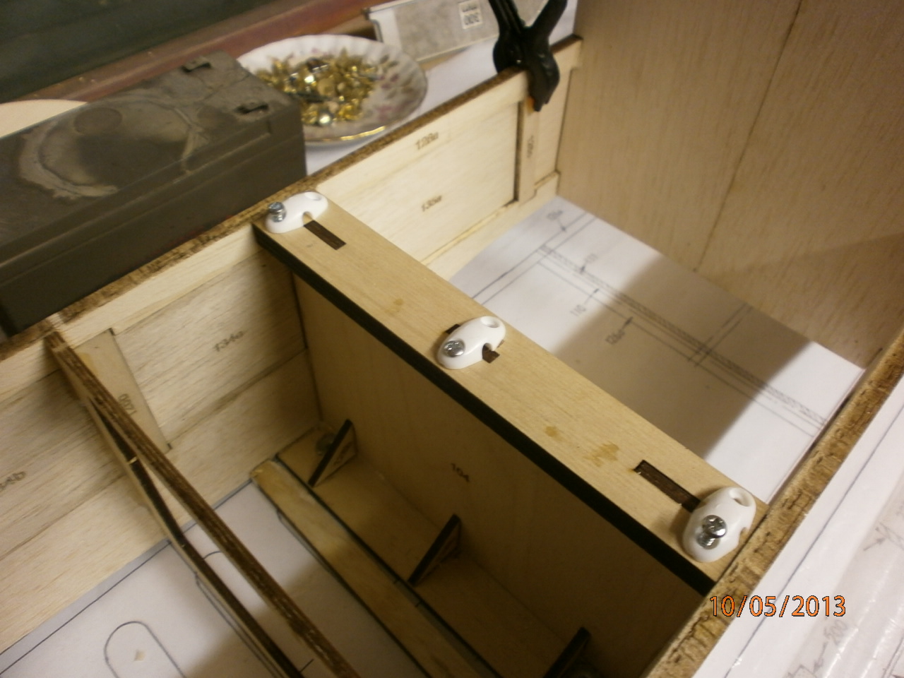
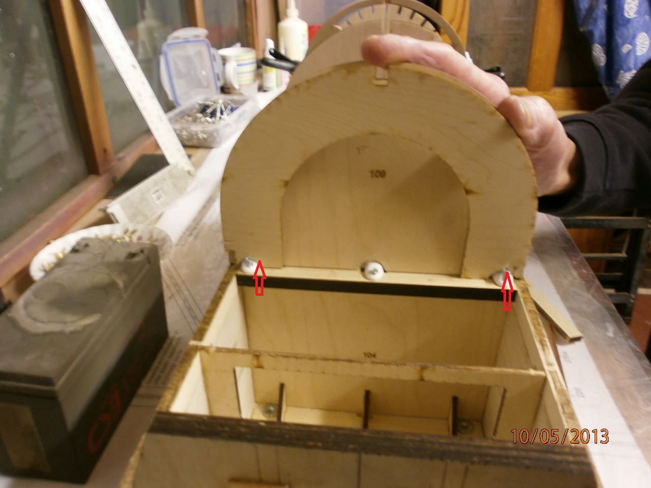
On reaching former 109
which it is located where the front cabane strut wires go.
These wires are held in place by saddle clamps and positioned as can be seen
in the second picture below.
 |
 |
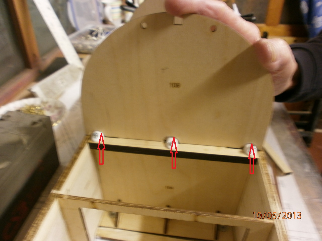
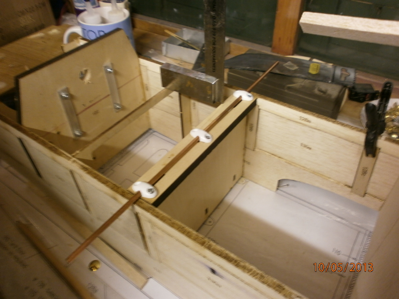
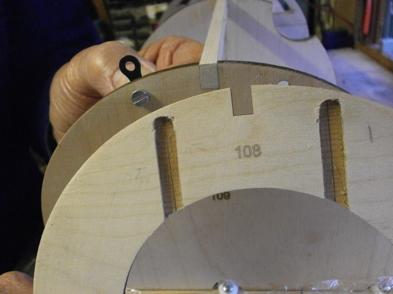
With these clamps in their required positions, there is a need to cut recesses in the 109 former, as it sits partway over the clamps for it to be in its correct position. See first picture below.
With the recesses cut out the former can be glued into position. This former as per plans sits tight against the cabane wire, so we introduced a piece of scrap wire through the saddle clamps to ensure an accurate fit when 109 is glued into its final position. To ensure that no glue bonded to the wire, it was coated with a fine film of Vaseline.
 |
 |
Once this former had cured we started to have a look at the front cowl formers 108 x3. One of these sits butt tight against Former 109 and again it became apparent that recesses would be needed to be added to the outer edges of this former allowing for the saddle clap positioning. See picture 2 below.
 |
 |
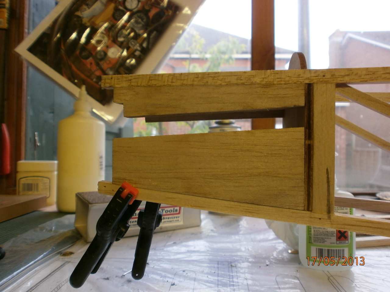
Having cut the
recesses in our 108 formers these where put to one side and our attention
turned once again to the back end of the fuselage.
The two top and bottom infill pieces 116u and 116i are added to the end of
the fuselage see picture one below along with the side pieces. It is
important to make sure that all these pieces are aligned square so as not to
induce a twist in the rear potion of fuselage.
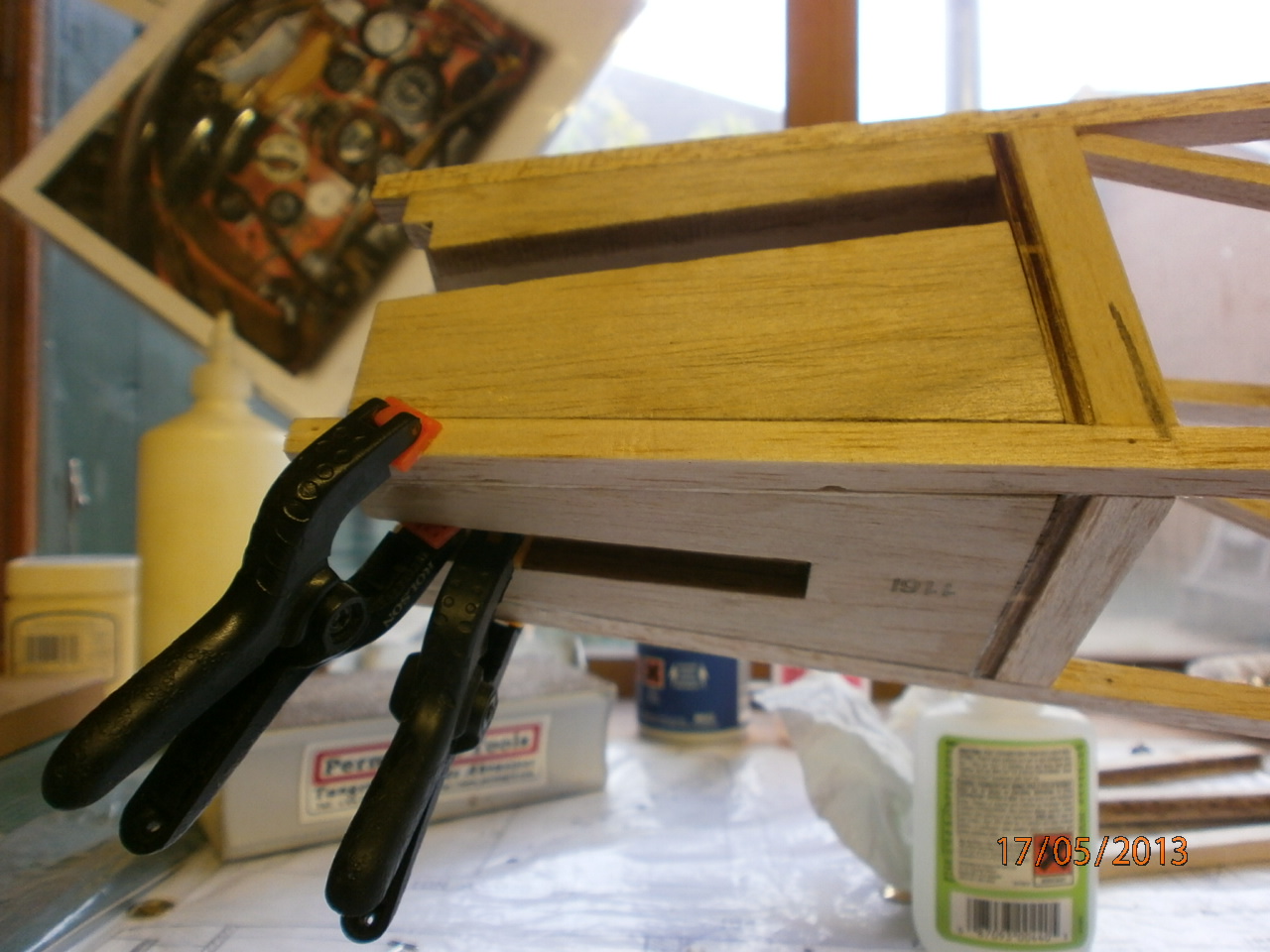
Once all dry our
attention turned to adding the top stringers to our previously installed
formers.
Note in picture two below that alternate stringers go part way along the
fuselage stopping at former 119
 |
 |
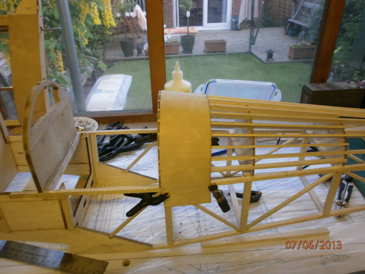
Before adding the rear decking
(picture one below) you need to align the forward end of this sheet with the rear portion of the cockpit decking. We dry fitted the rear decking into position and then carefully slid the cockpit decking under the front edge of the rear decking, scribing a pencil line on the cockpit decking where the two will join. The cockpit decking is then removed and cut on the scribed line. The two pieces are then re-dry fitted to ensure an accurate fit. The aim is to have the two decking sheets sitting equally over the respective former. Note: this process will need to be carried out on all the remaining decking sheets that make up the top of the fuselage.The second picture below showing the now installed front central stringers.
 |
 |
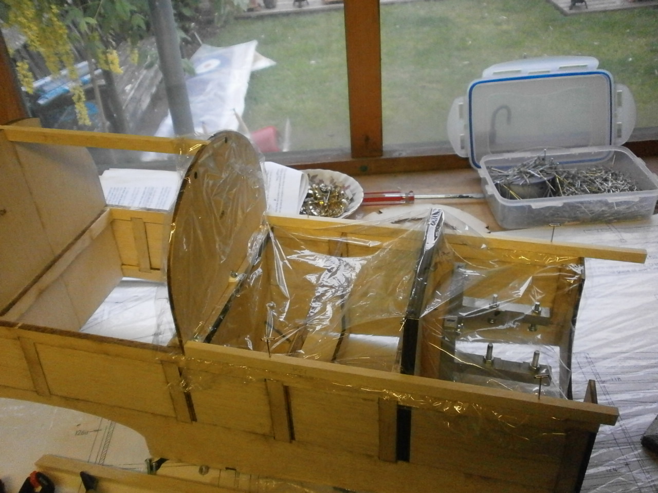
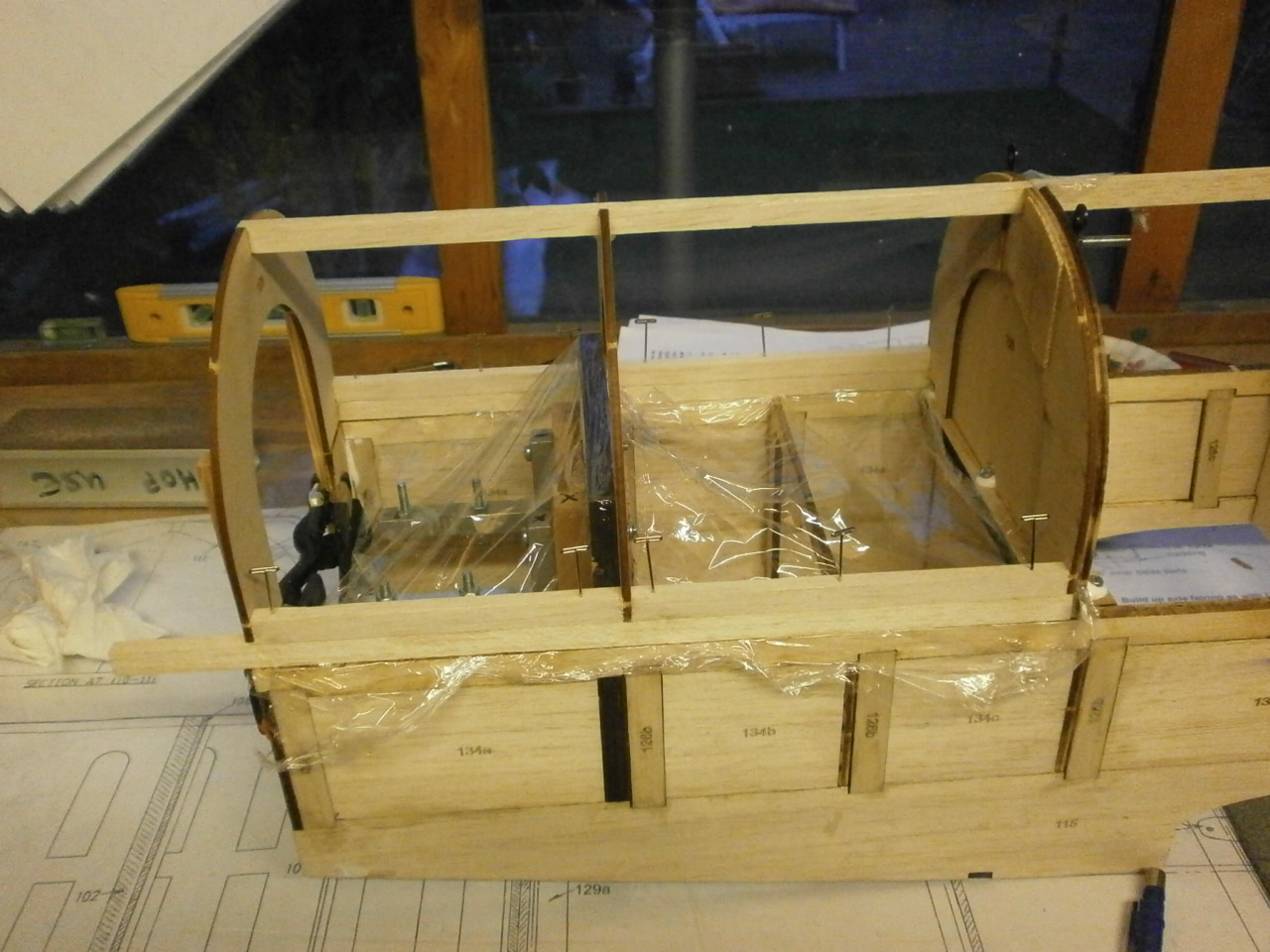
Our attention has now turned to the construction of the the fuselage cowl framework. The instructions suggest that this item can be made up in position on the fuselage thus ensuring a perfect fit.
To ensure that any glue used in the construction of this part does not come into contact with the actual fuselage we lined the touching surfaces with Clingfilm, see first picture below.
In the second
picture you can see that we have used a bolt (x2) to hold rigging tags
in place. The instructions actually use the word screws and (we found the
screws self tapping to be two small) these can be ground off where they
protrude through the former that the first cowl former rests tightly against
and therefore allowing it to fit into place without obstruction.
Also later on when building and installing the radiator you are instructed
to cut the radiator into two, gluing on of the sections to the fuselage and
the other to the cowl.
We want to keep the radiator as one piece as it would have been on the full
size and therefore this will be glued as one to the fuselage.
To necessitate this modification it requires that the cowl to be able to
slide down between the fuselage former and the radiator. With our two bolt
heads now protruding and obstructing the cowl, we had to cut a recess
channels running down the first cowl former directly where the bolts come
into contact with it.
 |
 |
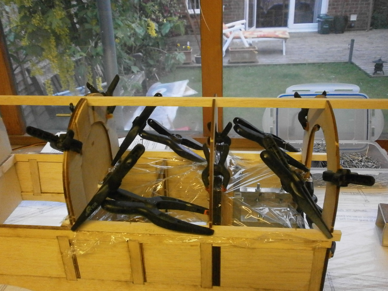
In doing this it has obviously weakened the former so strips of spruce have been used to re-instate structural stability. See first picture below.
The second and third pictures below the structure glued and clamp in place.
 |
 |
we are aiming to modify the cowl further now that we have the basic structure, adding individual access panels as per the full-size. The plans and instructions only show and tell you to cover the frame with 0.4mm ply
 |
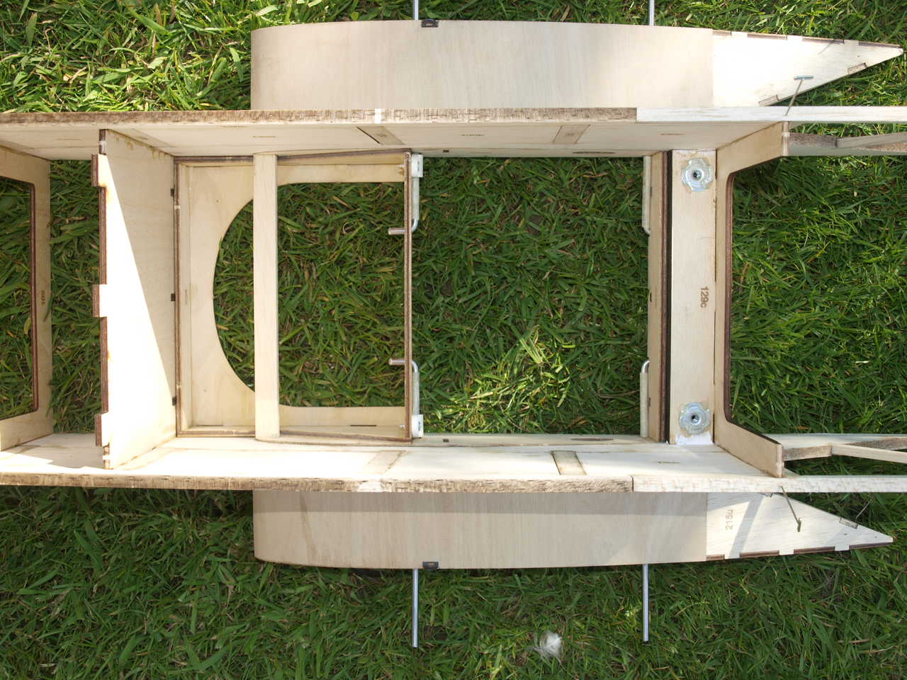
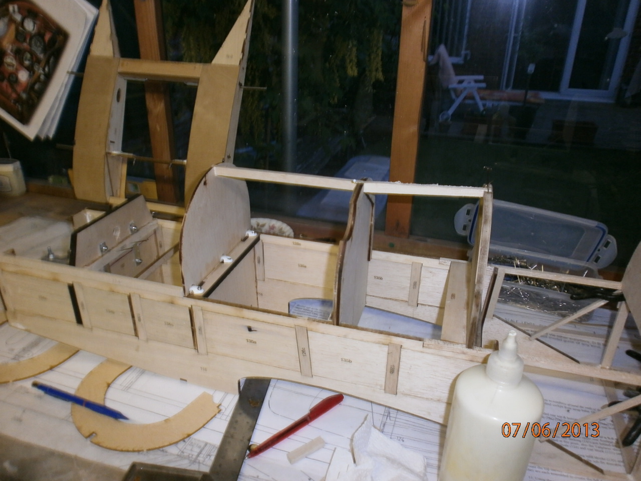
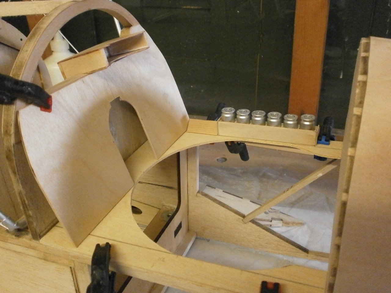
We decided that with the basic fuselage structure complete, we would set about starting on some of the cockpit detail. In the first picture below you can see that we have added a ply mid section that has been cut to shape as per the full size. In the second picture you can see the instrument panel which is set at an angle. The cut out in the middle will house the compass. You will also see the flare cartridge housing with the flares in situ. The housing has been made from 1/32 ply and the flares are cut down riffle cartridges sprayed silver.
 |
 |
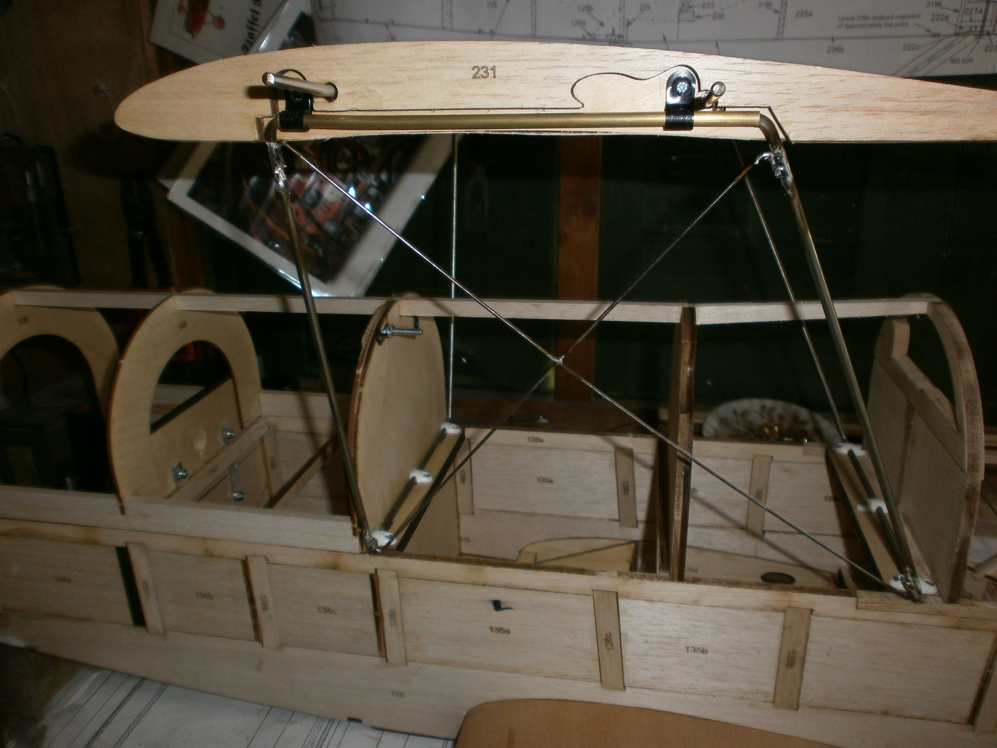
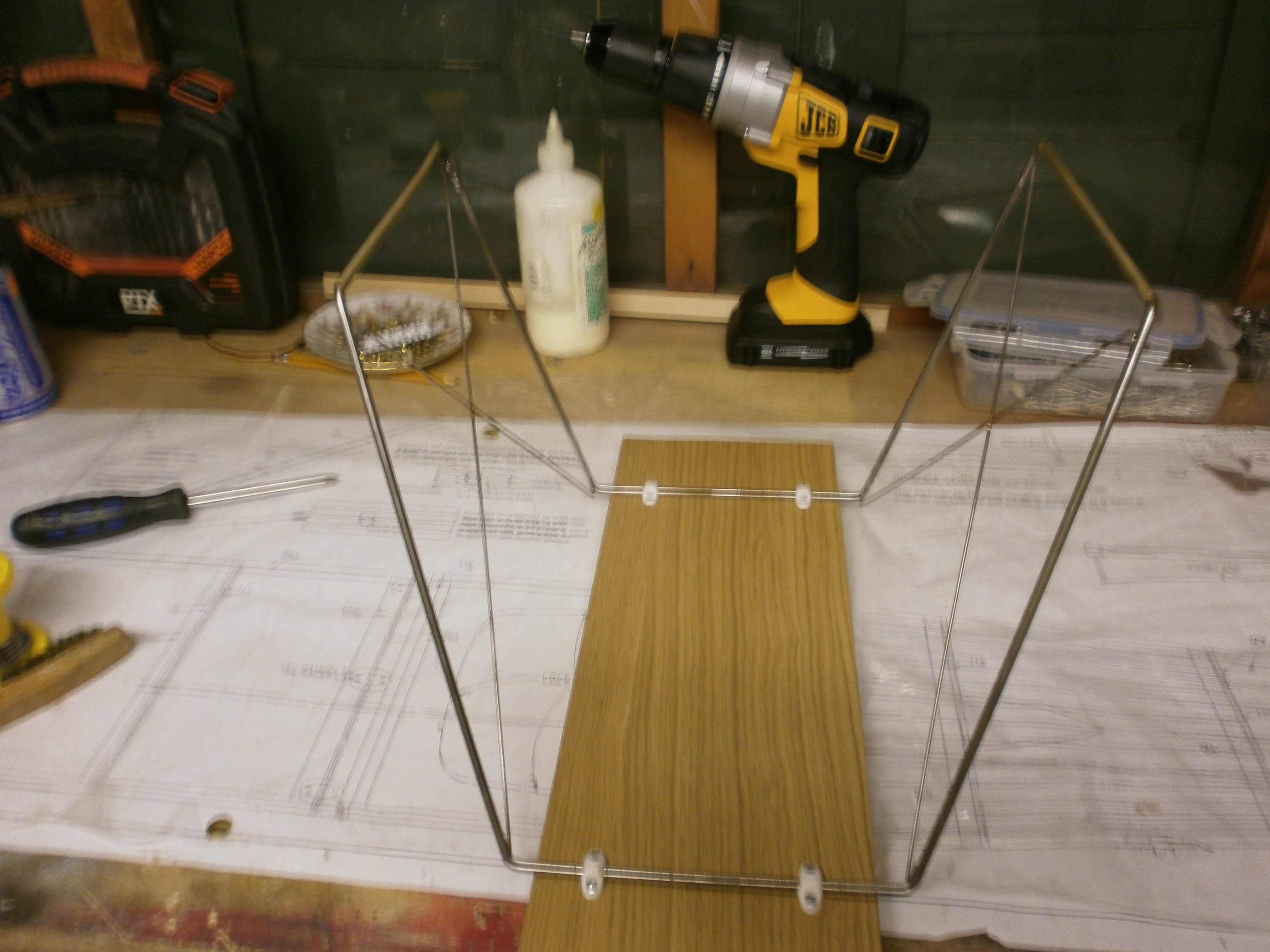
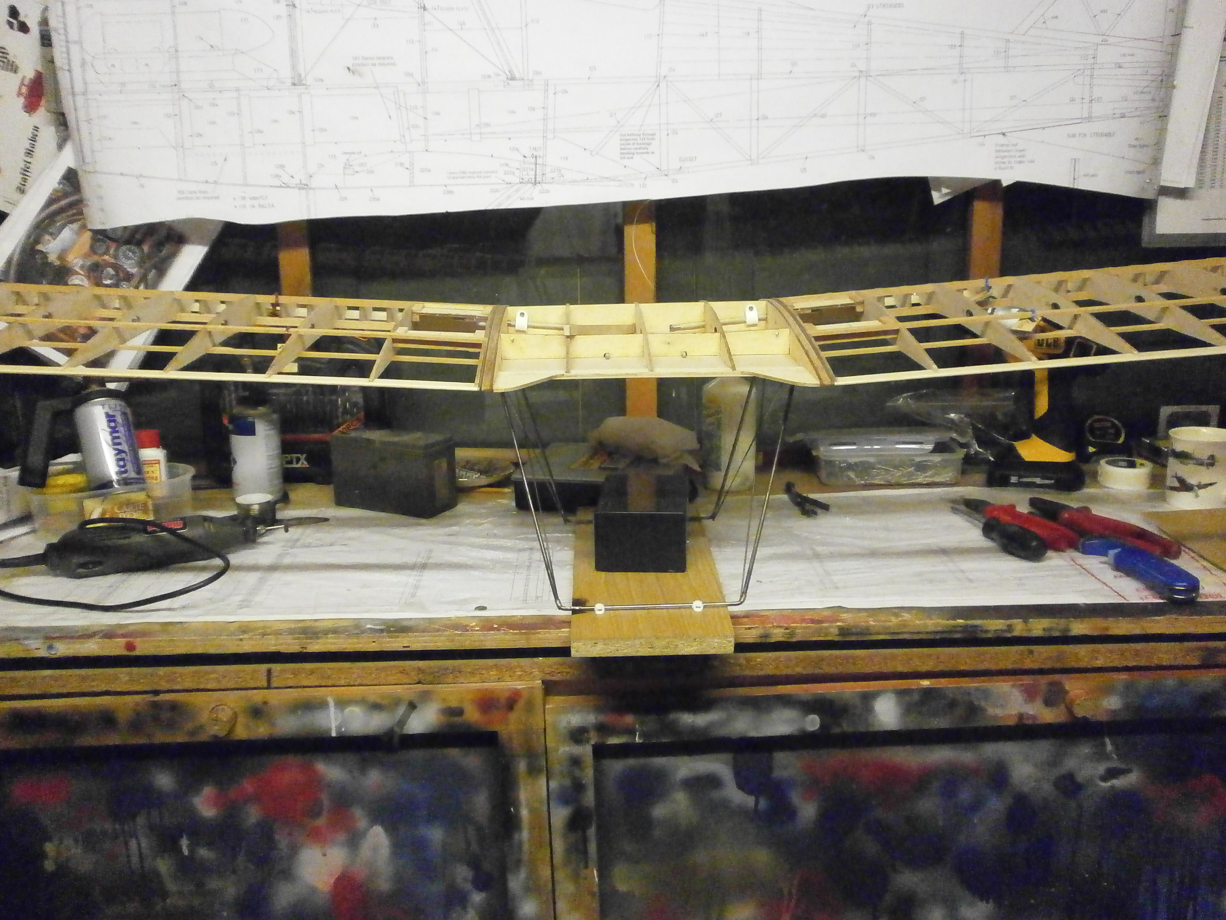
The following pictures are of the centre section cabane struts being setup and soldered. If you have followed my Sopwith Pup build then you will know that this is my least favourite part of building a model.
 |
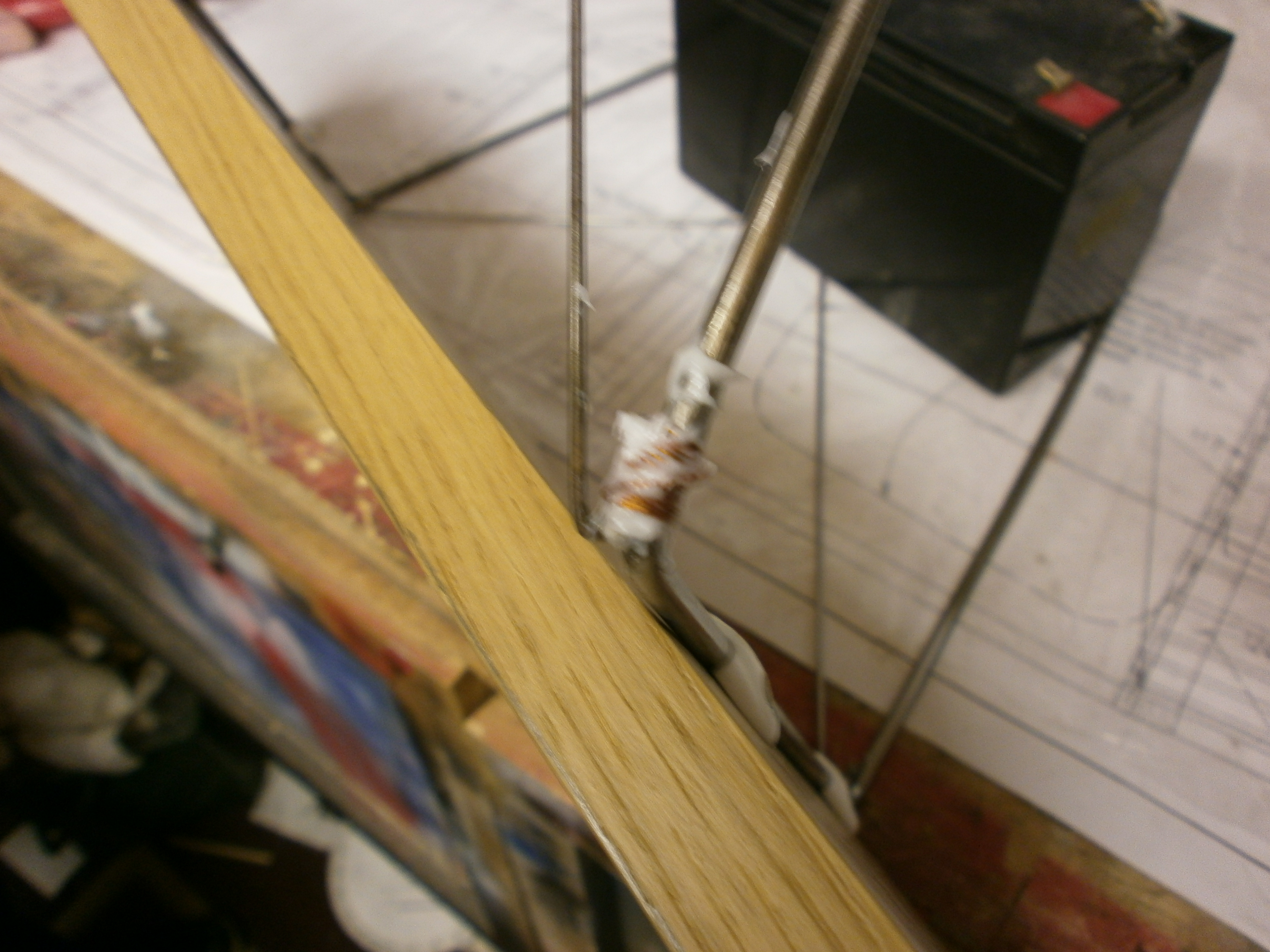 |
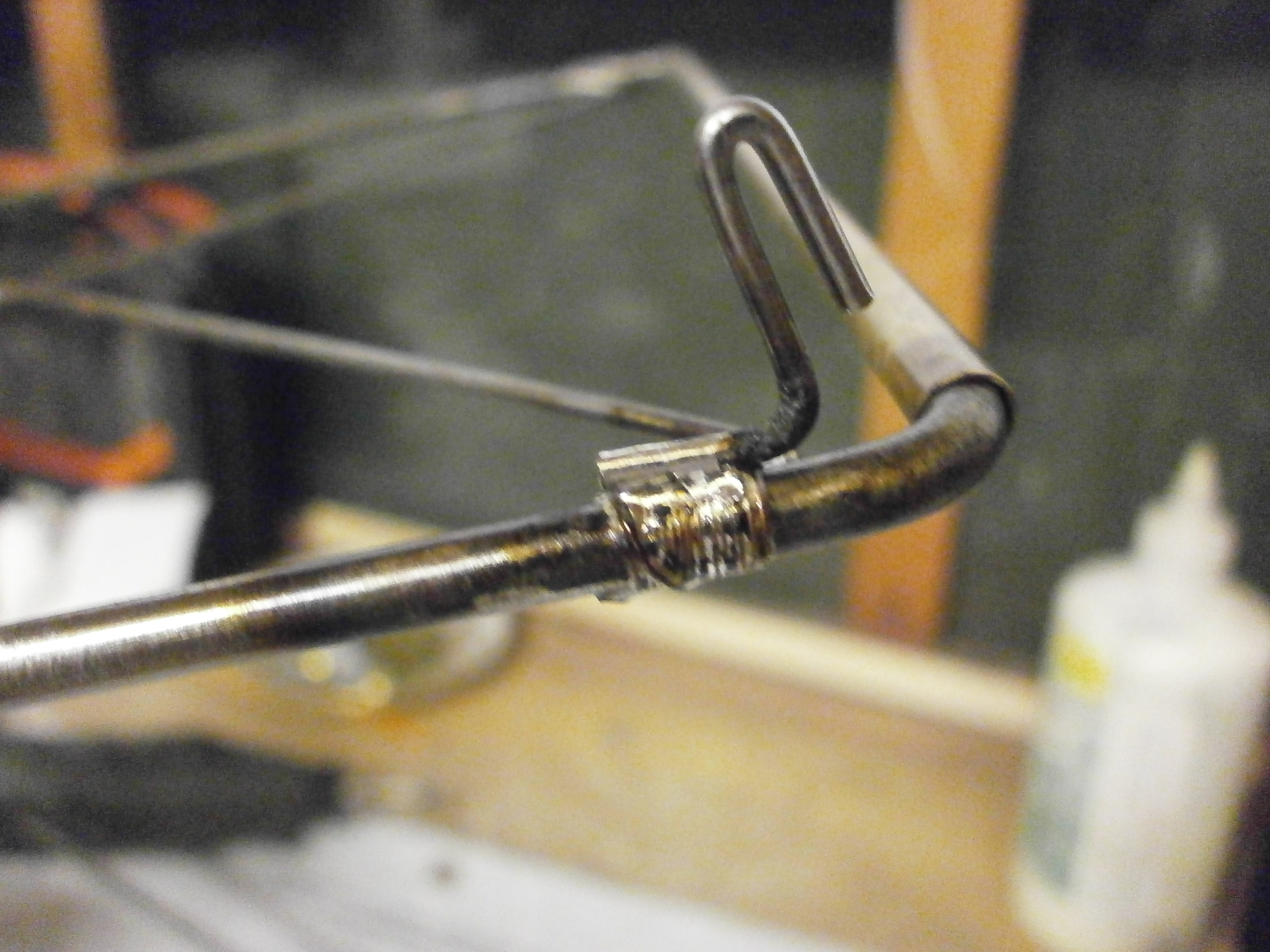
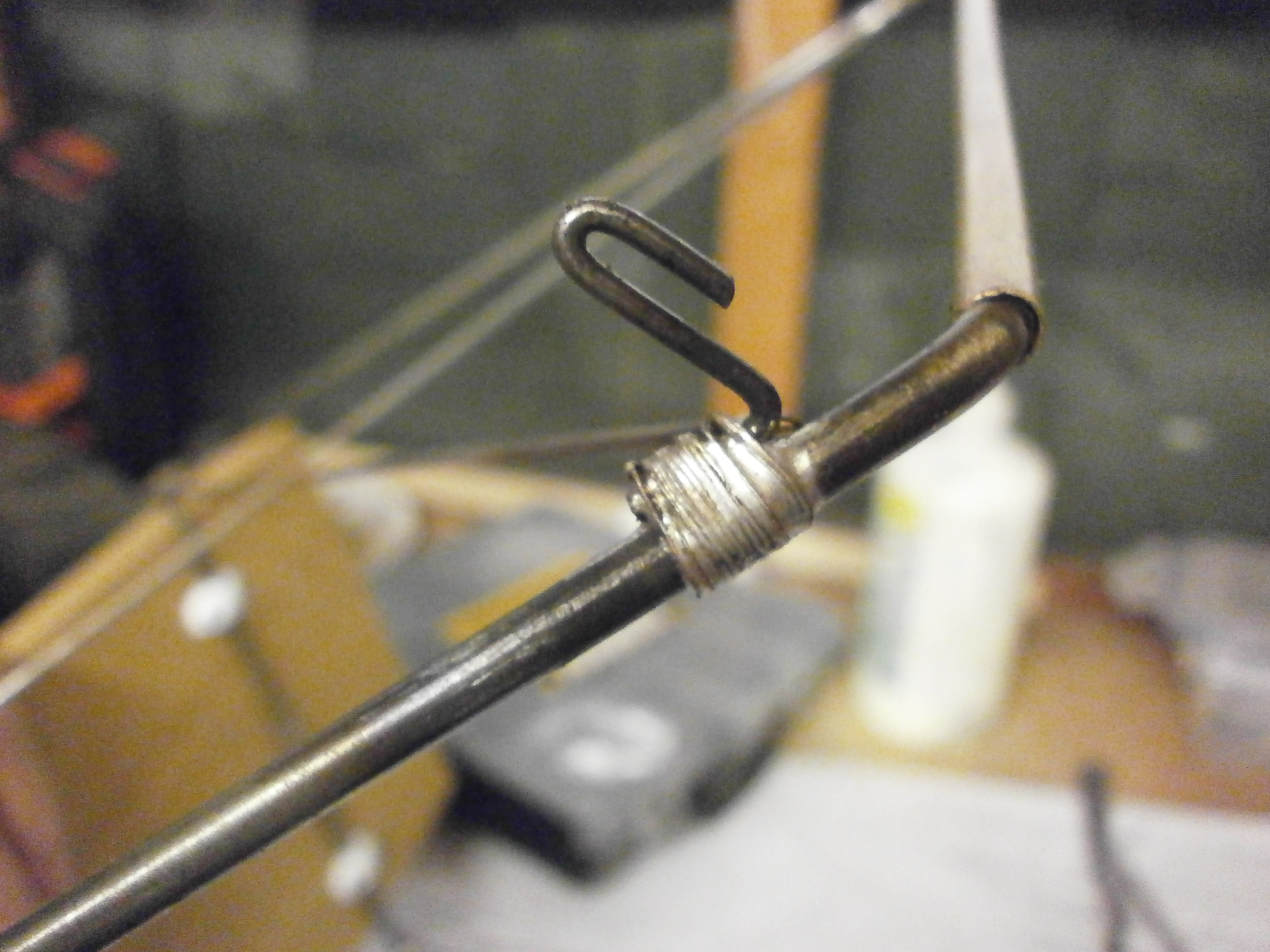
Once all wired up the assembly was carefully removed from the model and secured to a flat board and then soldered up. the second picture here shows the rigging hooks tack soldered into place ready for wiring
 |
 |
The next pictures showing the final result and the top centre section in place checking that everything is in its correct position and not obstructing the wings.
 |
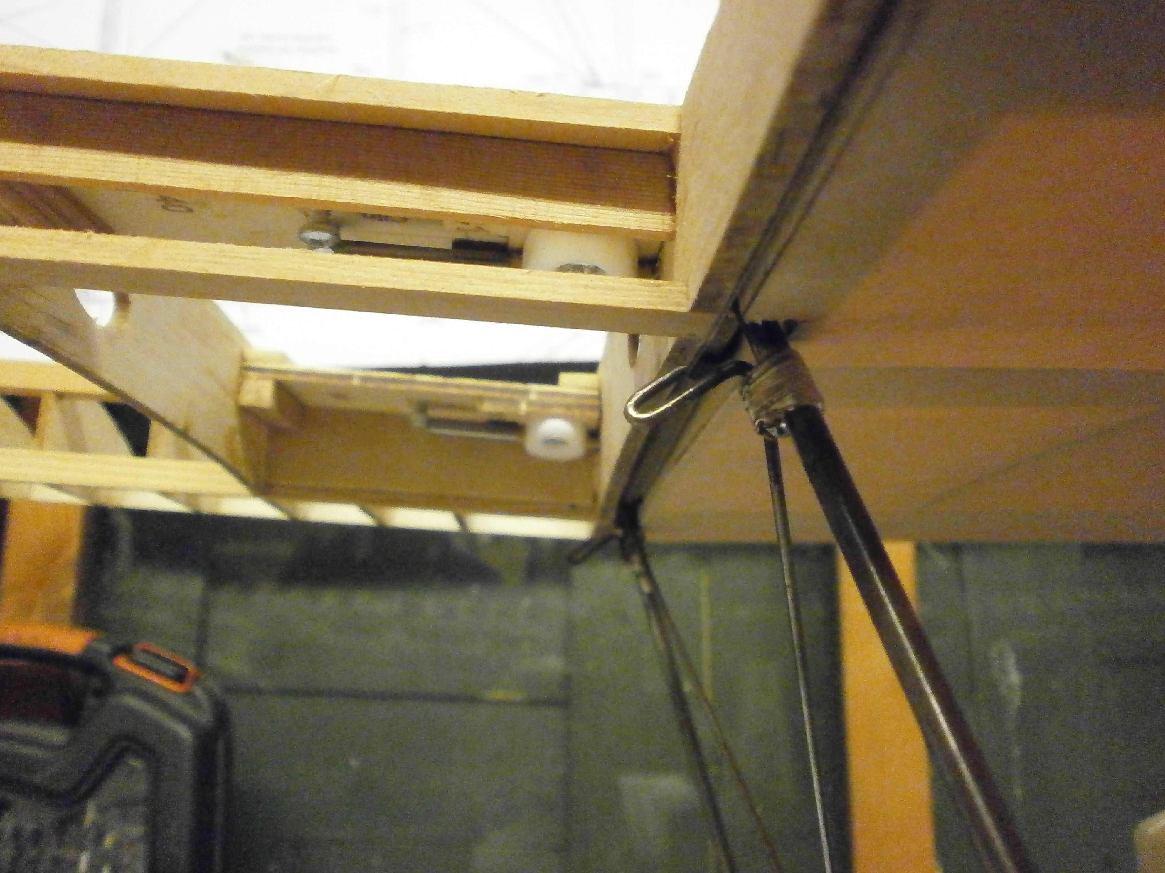 |
Wing located into centre section to check everything is square. The cabane assembly can now be reinstalled back onto the fuselage
 |
Stabiliser Elevator Build
Fuselage page
Fin & Rudder Build
Wing Build Bottom
Wing Retaining
System
SE5A Full size detail gallery
Landing gear
SE5A Cowl
TAIL ASSEMBELY
Fuselage page 2