Engine Installation
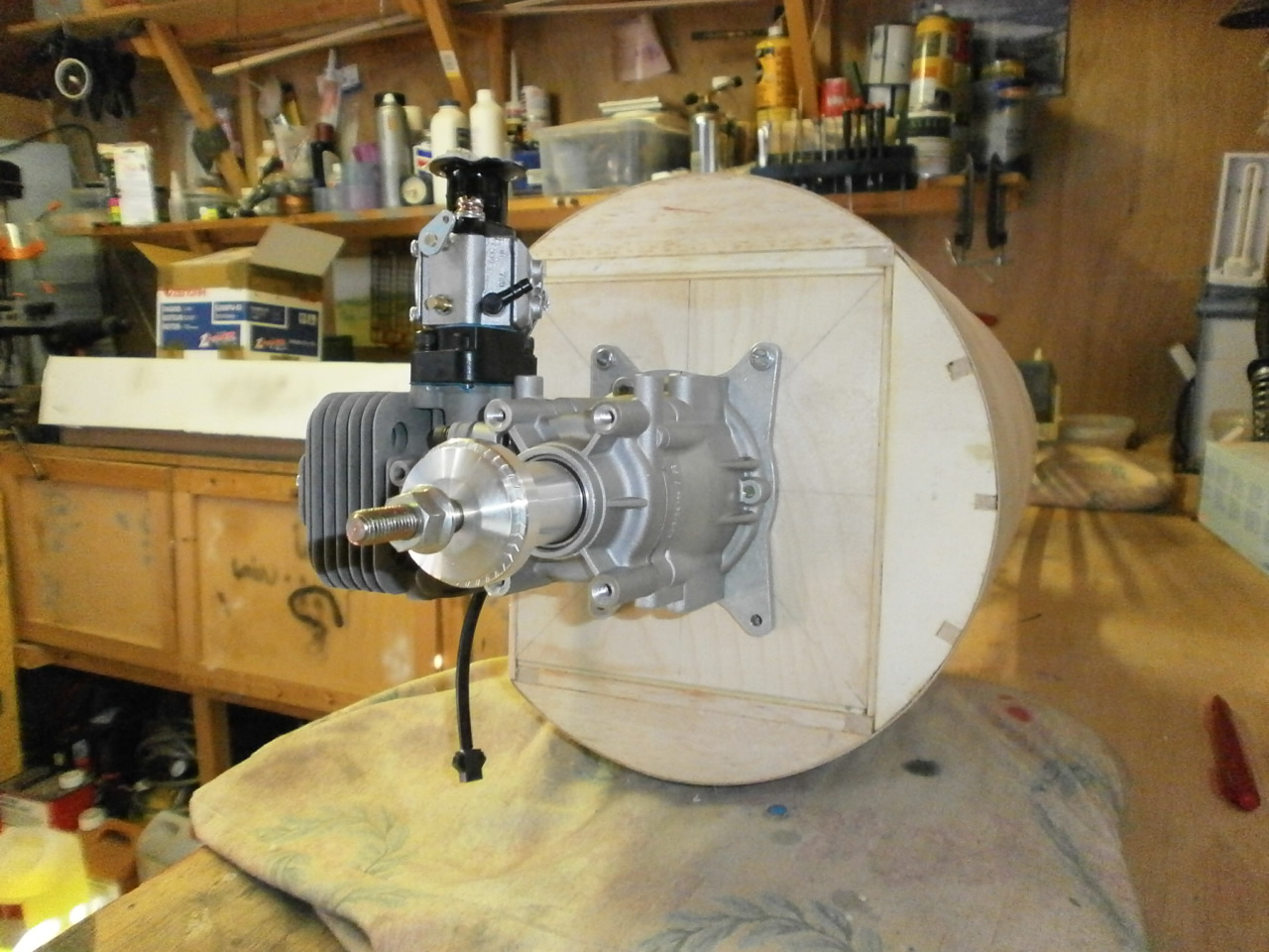
The Engine being used for this model is a Zenoah G26 ei. This fits very neatly into the cowl with just the Spark plug and cap pocking out of the bottom of the cowl.
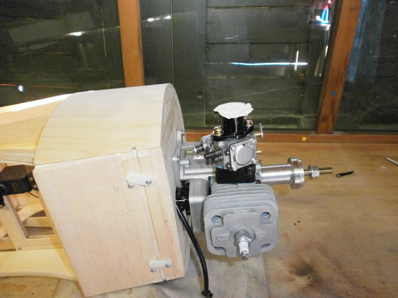
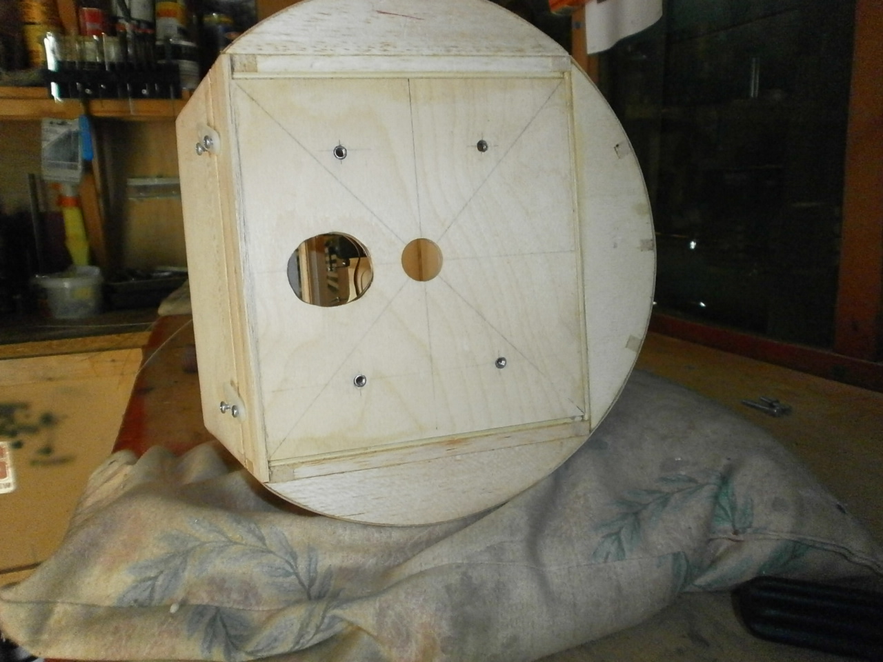
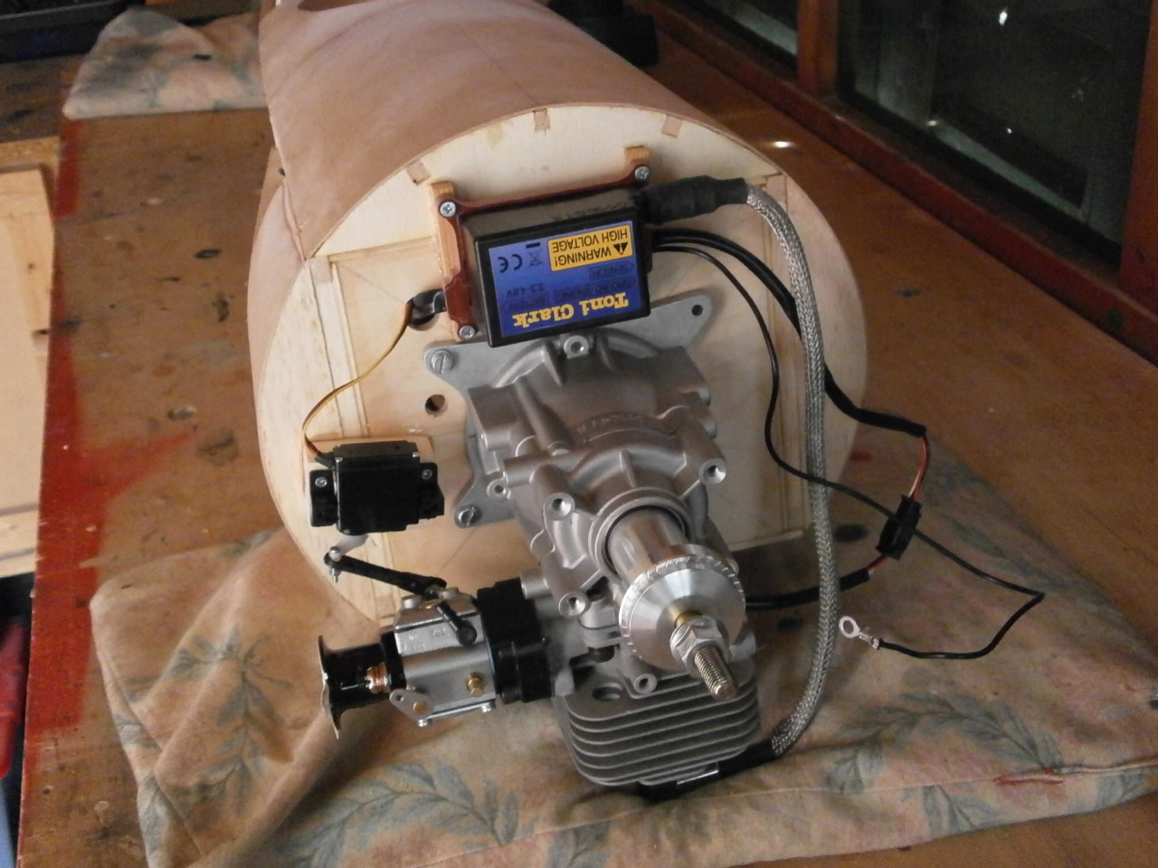
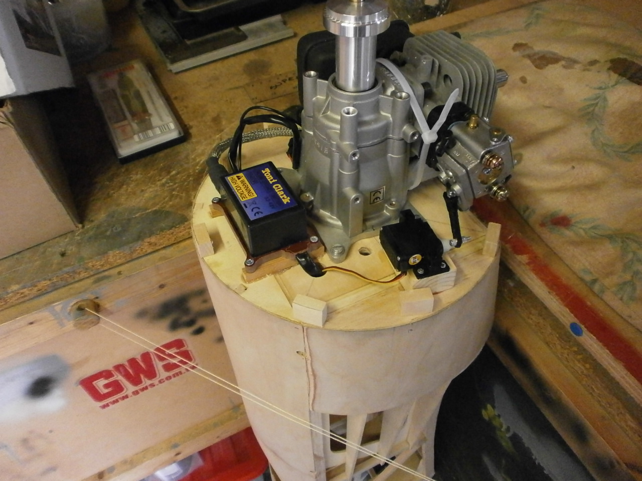
As you can see from the picture below a cut-out has been added to the firewall, below the centre hole. This had to be done, as the ignition censor on the Zenoah is located on the back of the engine crank and protrudes about 2mm from the mounting plate face. Once completed the engine can be placed into position using bolts located into the previously marked and drilled holes with captive nuts that where inserted during the fuselage construction see pic 2 below .
|
|
|
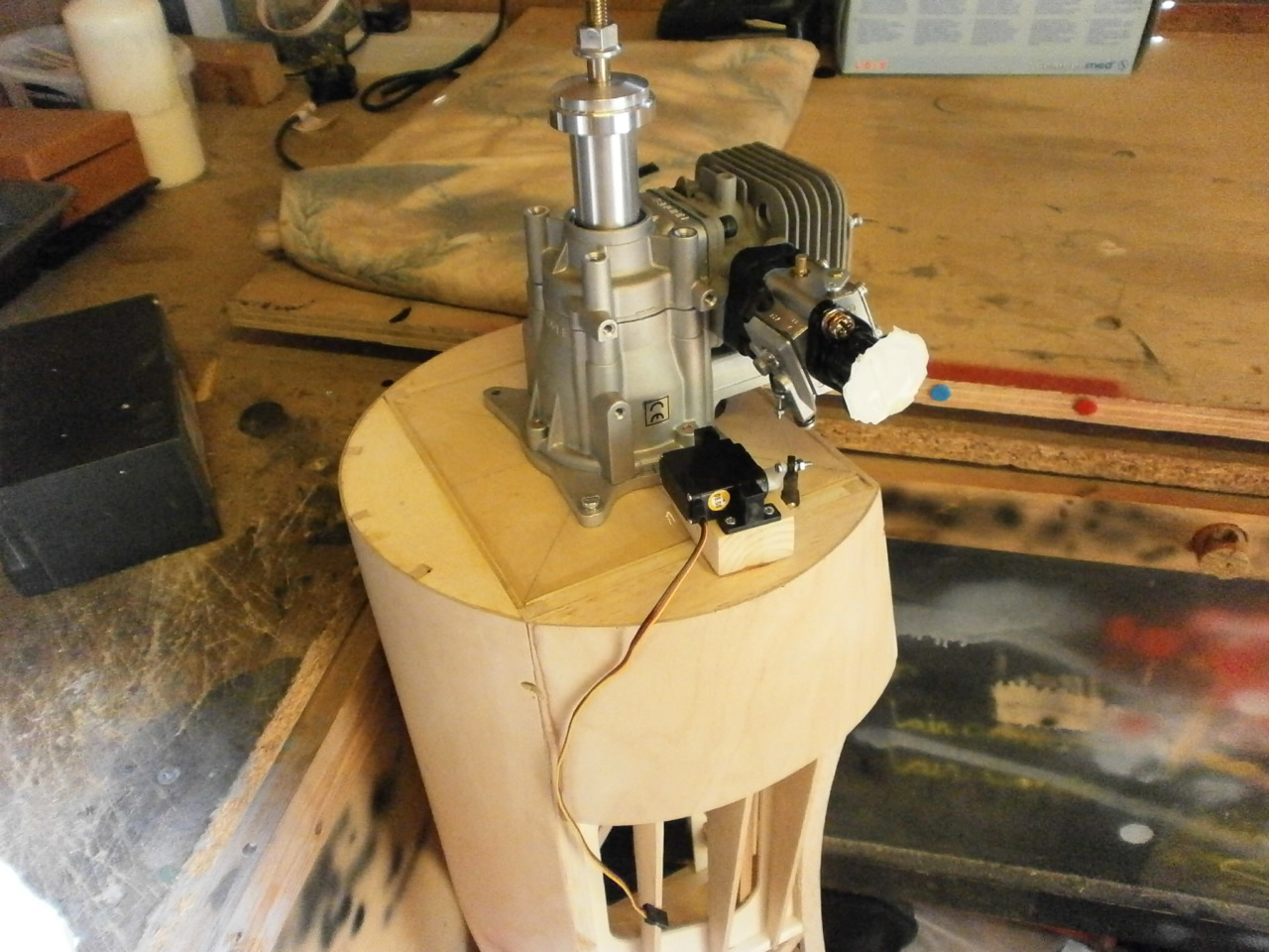
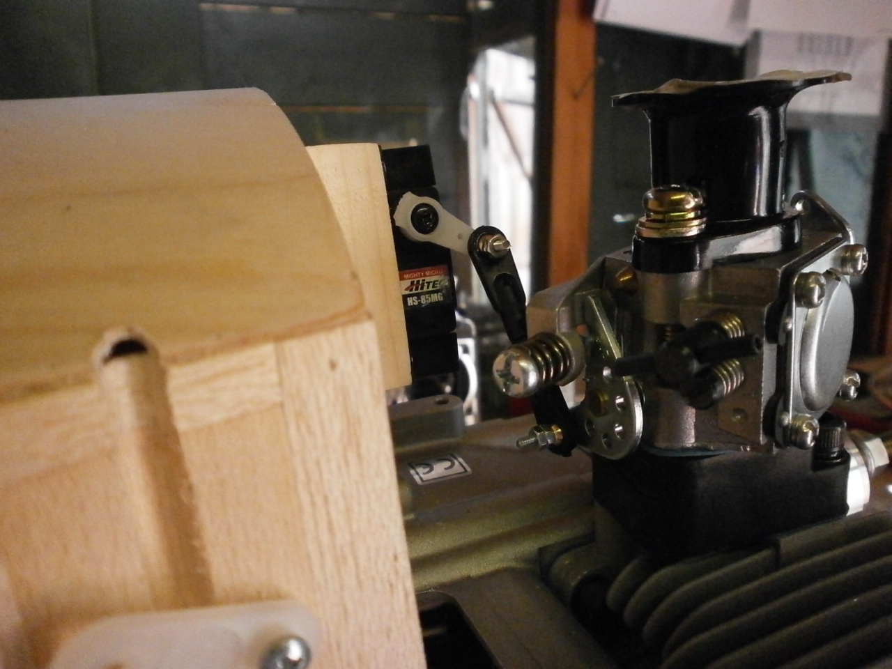
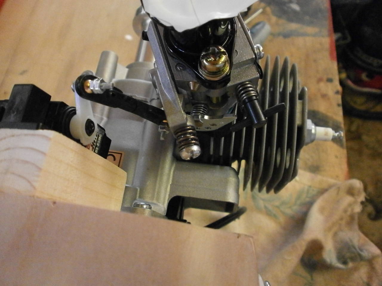
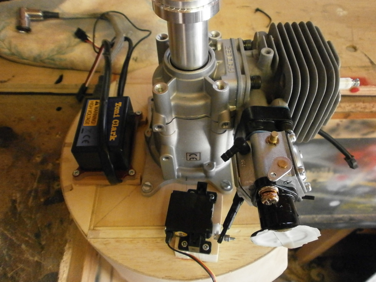
The carburettor arrangement on the Zenoah has the throttle parallel to the firewall ( not conventional as glow engines) making it difficult to set up. After much thought and deliberation the solution came to me. I would mount a servo to the firewall and create a linkage system from from ball mount linkages that would give an unrestricted free movement of the throttle. The only problem here was that with the servo mounted directly to the firewall the angel that was required to connect the two together caused binding of the servo when dry tested. To overcome this a block was introduced bringing the servo closer to the throttle. see video below or click here.
|
|
|
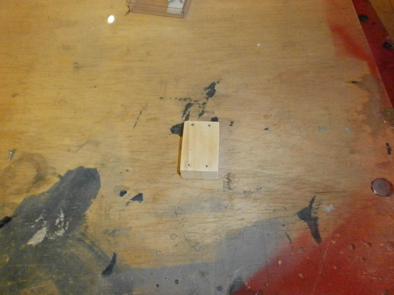
Once happy with the positioning of the servo the servo was mounted to the wooden block and this assembly then epoxied into place see pictures below.
|
|
 |
Once cured the linkage is attached between the two and tested with the radio to ensure everything is working properly
|
|
|
Engine installation video 1
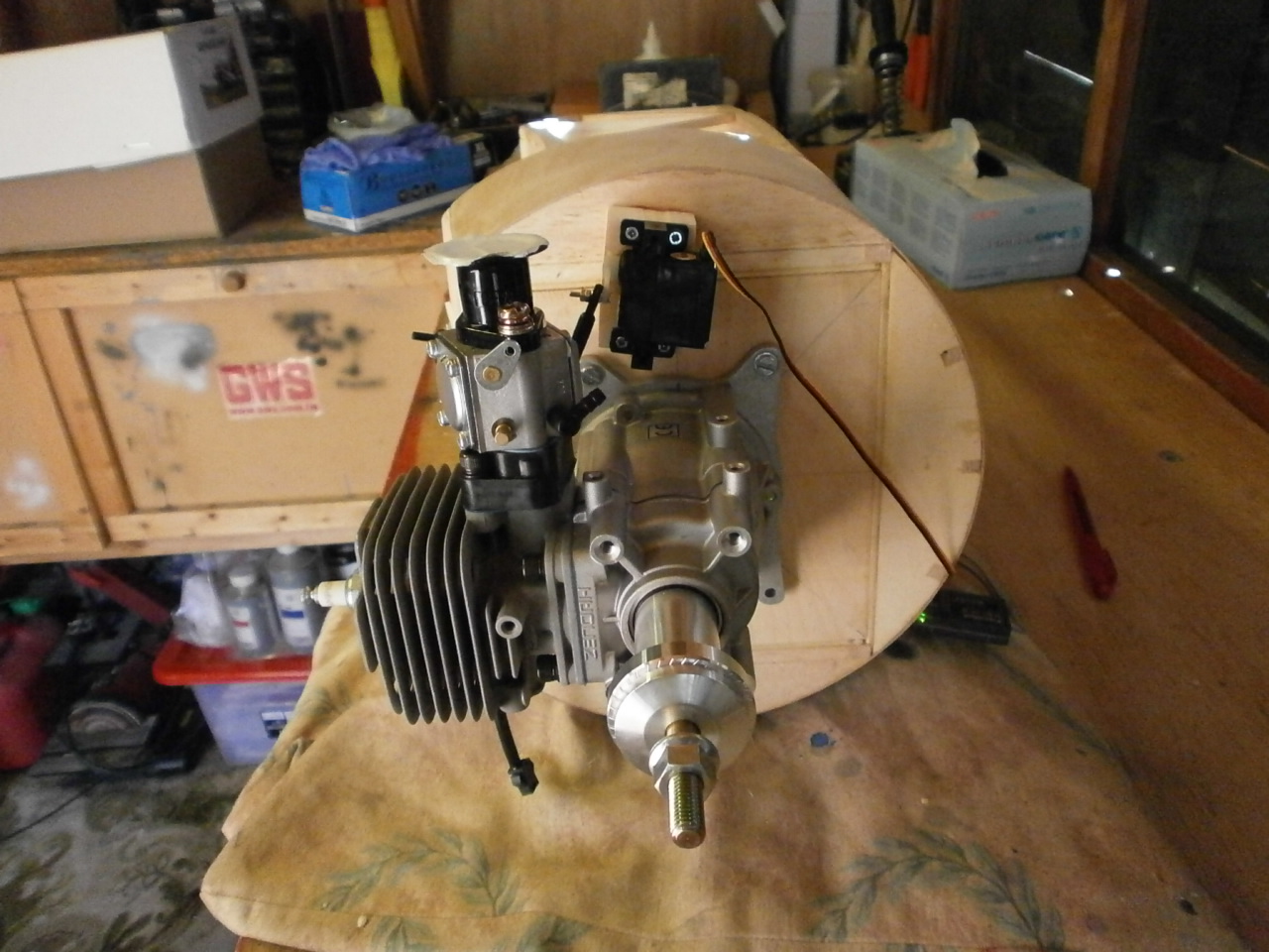
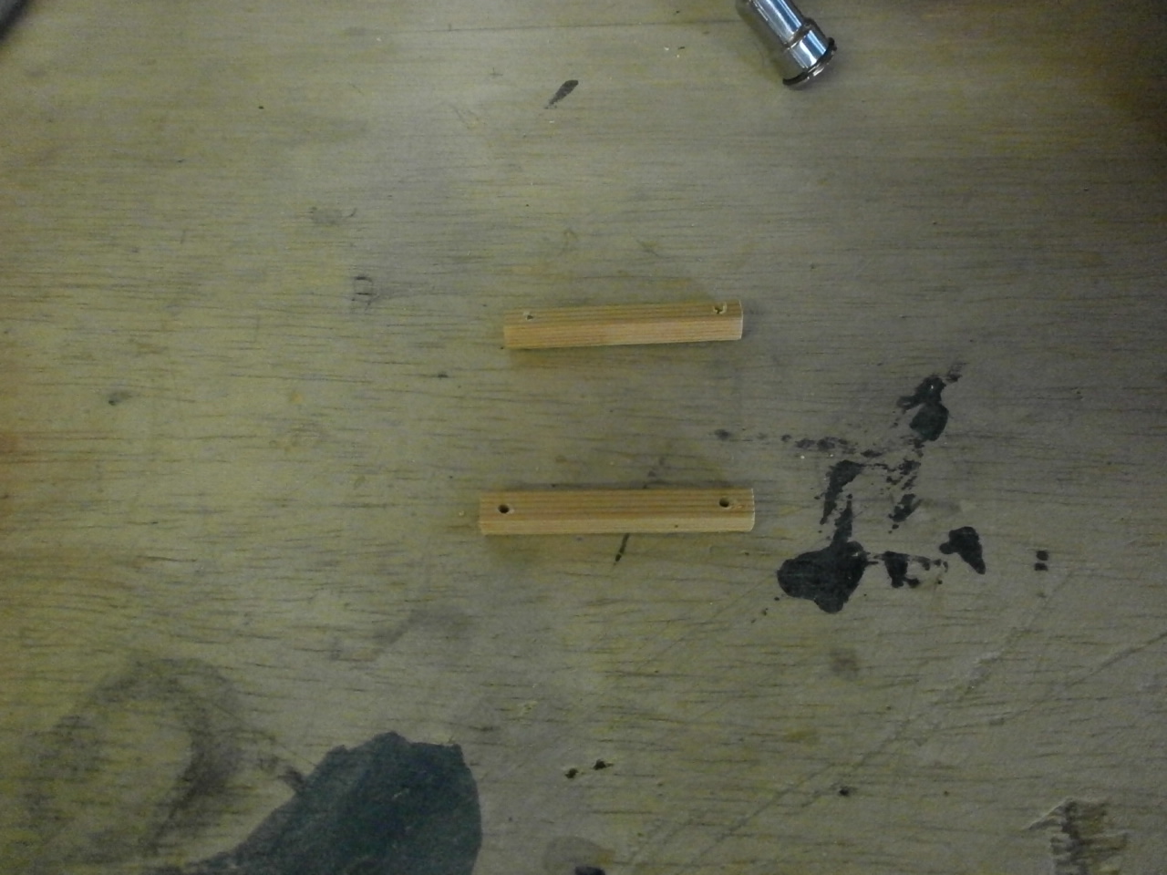
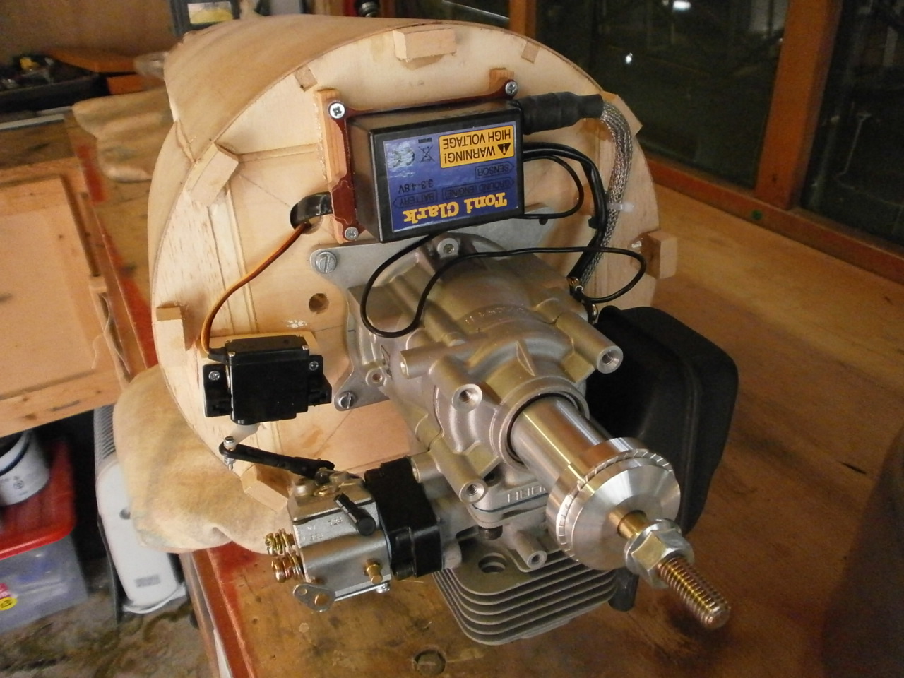
The next job is to install the electronic ignition module. Reading the instruction manual that came with the engine, it tells you that the back of the module needs to be clear of the mounting surface with free circulation of air around it, as the unit becomes hot during operation. This is quite simple to execute by raising the unit about a 1/4 inch with two lengths of square spruce. see pictures below
 |
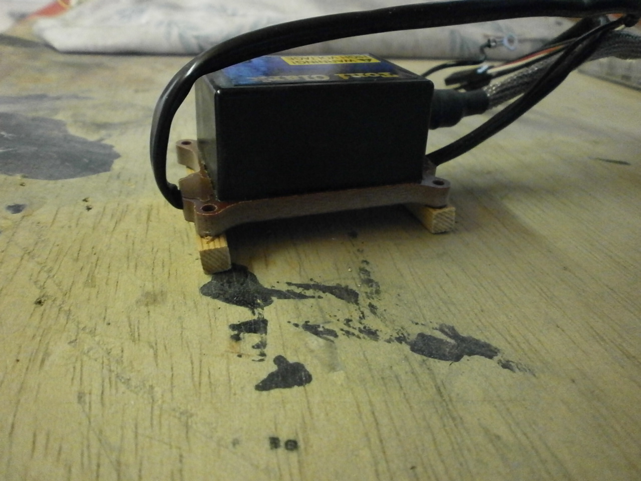 |
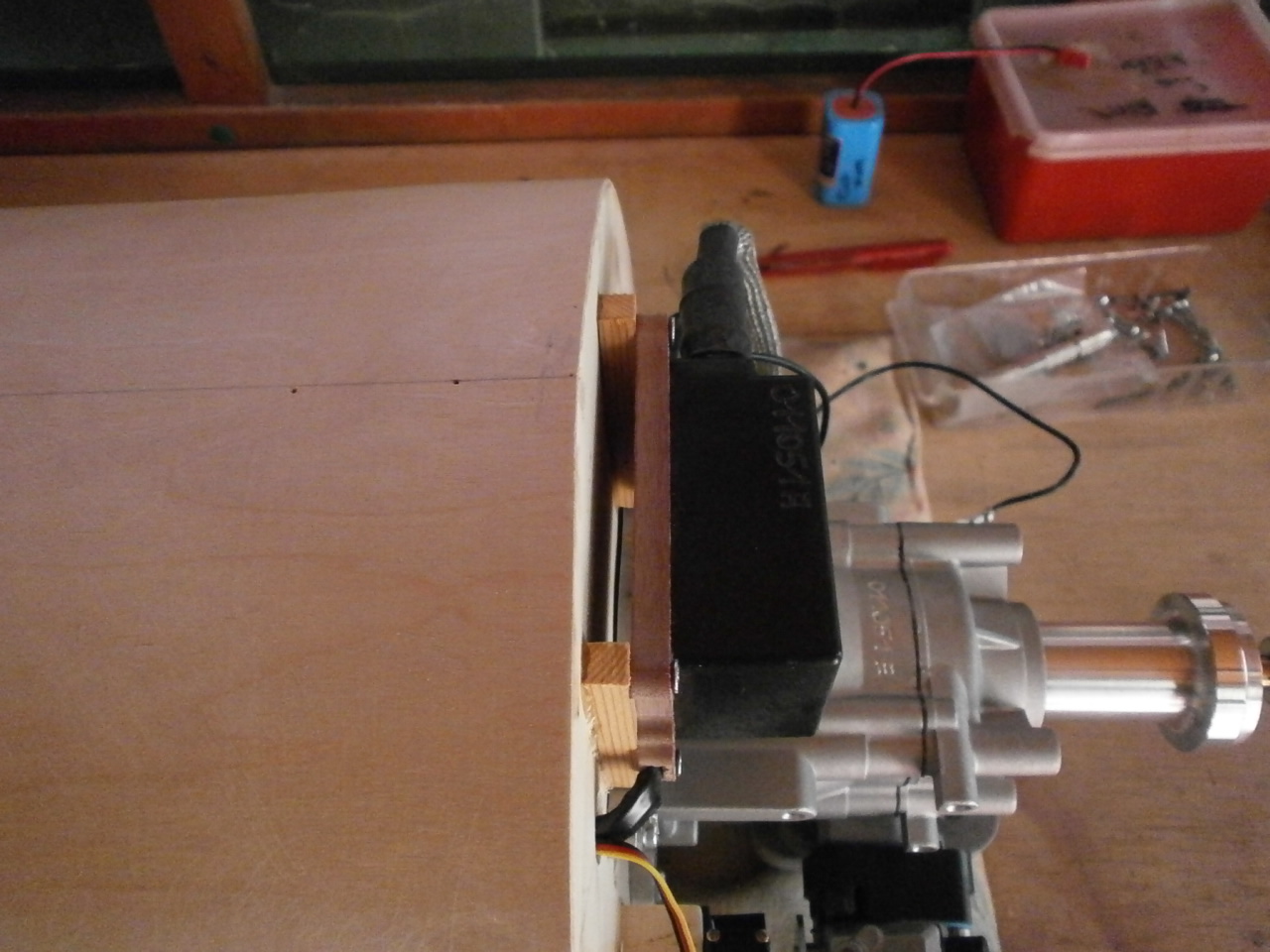
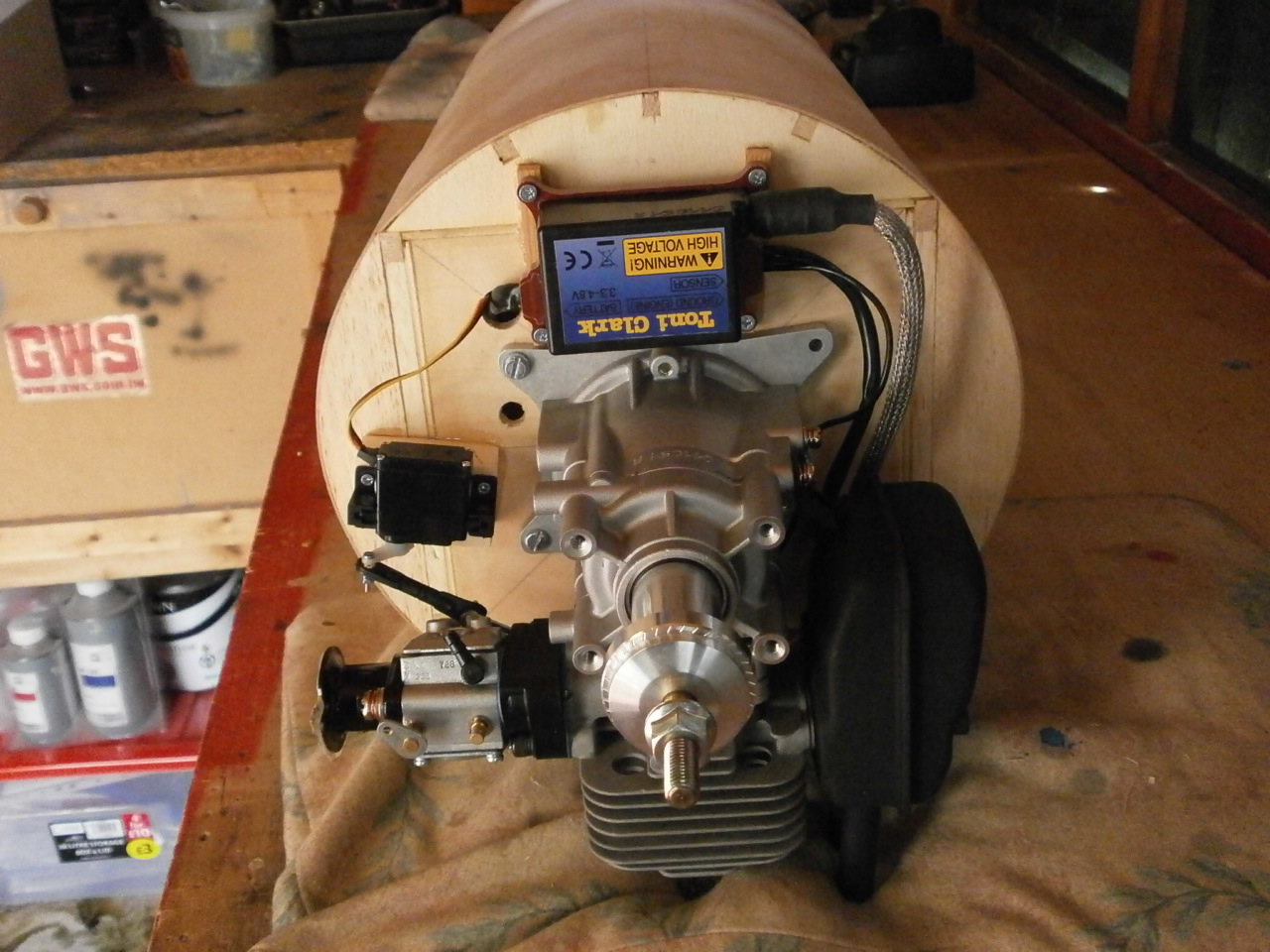
The unit is then mounted to these and epoxied into the predetermined location on the firewall. Again it is better to dry fit this in the first instance to ensure all the wire harnesses will reach to their final locations. The two pictures below show the unit in place and the gap created allowing unrestricted air follow around the unit.
 |
 |
The last two pictures below show the now drilled holes allowing the wire harnesses be routed back through to the fuselage where they will be married up with the battery and on off switch. Note the hole next to the engine mounting. This is ready to receive the fuel tube that comes from the fuel tank to the carb.
 |
 |
Engine installation Video 2
With the engine now installed its time to turn my
attention to installing the cowl.
Again I have not been looking forwards to this. The aluminium cowl was expensive
and has to have the scale opening in its underside cut out. There's no room for
expensive mistakes.
The first thing then is to take measurements from the
firewall to the centre of the spark plug and transfer these to the outside of
the cowl. Then with a small drill bit, drill a pilot hole at the mark. Then
select a drill bit that is slightly larger than the diameter of the spark plug
and open up the hole.
The cowl is then offered up to the fire wall where if all measurements are
correct, the plug should poke through the drilled hole. Once happy with that,
further measurements where taken from the fire wall to the locations of the two
exhaust pipes coming down from the main exhaust body. These measurements
determine the width of the opening with a further few mm added to ensure neither
come into contact with the edges of the cowl opening once the cowl is in place.
The length of the opening is as suggested in the instruction manual. Once happy
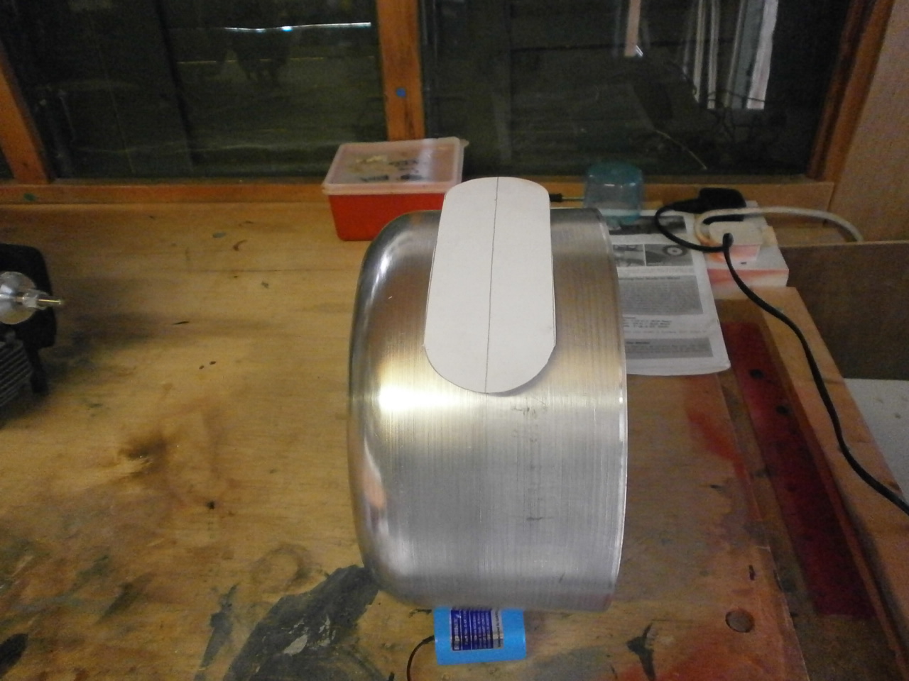
with all the measurements these are transferred onto card generating a template.
This is used to mark out the cutting marks on the cowl. See picture below.
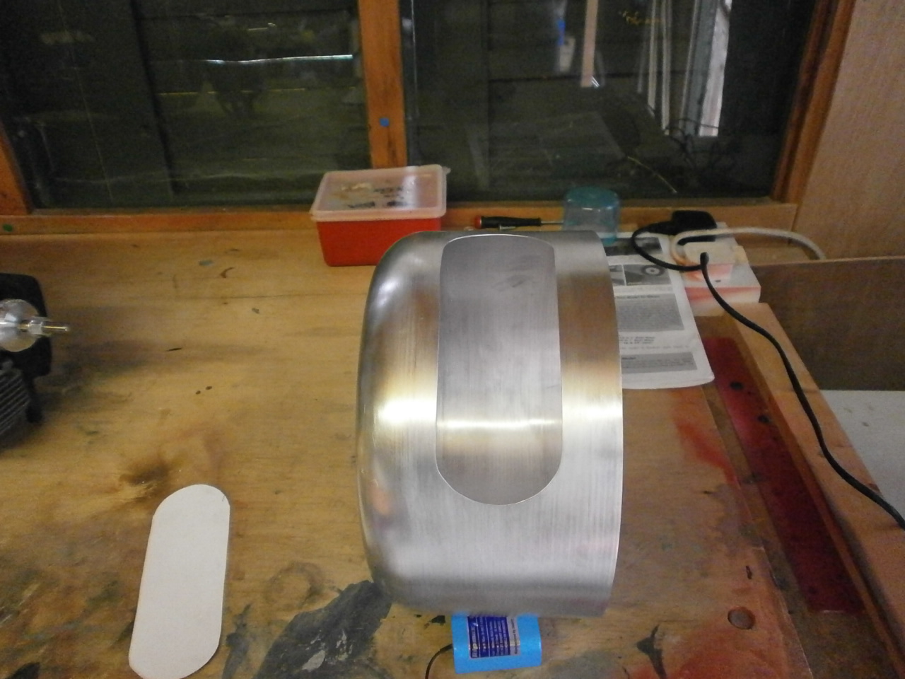
As I don't have any special cutting equipment to cut this aperture out, holes where drilled around the curved portion of the opening and the straight portions cut out with a junior hacksaw blade taking about an hour to achieve. The curves where then filed to their final shape again about another hours work. See second picture of finished opening.
 |
 |
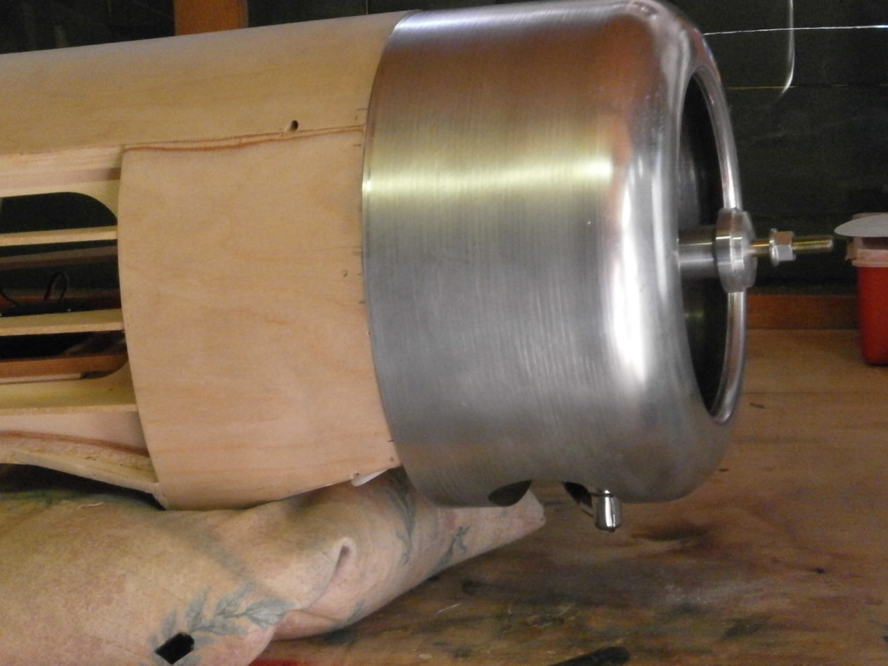
| Once happy with
the cut out, the cowl is offered up to the firewall and aligned into
position and thankfully everything fitted a treat.
Next job on the list is to locate the cowl mounting
blocks (7). As these are going to be placed on the edges of the fuselage
firewall and the cowl needs to fit flush with the fuselage sides, I decided
that the block would need to take on the contour of the fuselage sides. This
is achieved by offering the blocks to the firewall so they are just proud of
the fuselage sides and marked with a pencil to show the contour. see picture
to the right. |
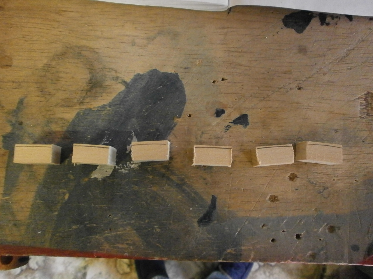 |
With the fuselage standing on end, the blocks are dry fitted into position making sure that no further sanding adjustments are needed. Once happy, they are glued into place using 30 min epoxy. I used a little gig made from scrap cowl aluminium and balsa (see video ) to ensure that blocks where just recessed enough to allow the cowl to fit flush with the fuselage sides. Pictures below showing blocks before and after gluing
 |
 |
With the blocks now in place the cowl is again test fitted to ensure that everything fits flush. See first pic below.
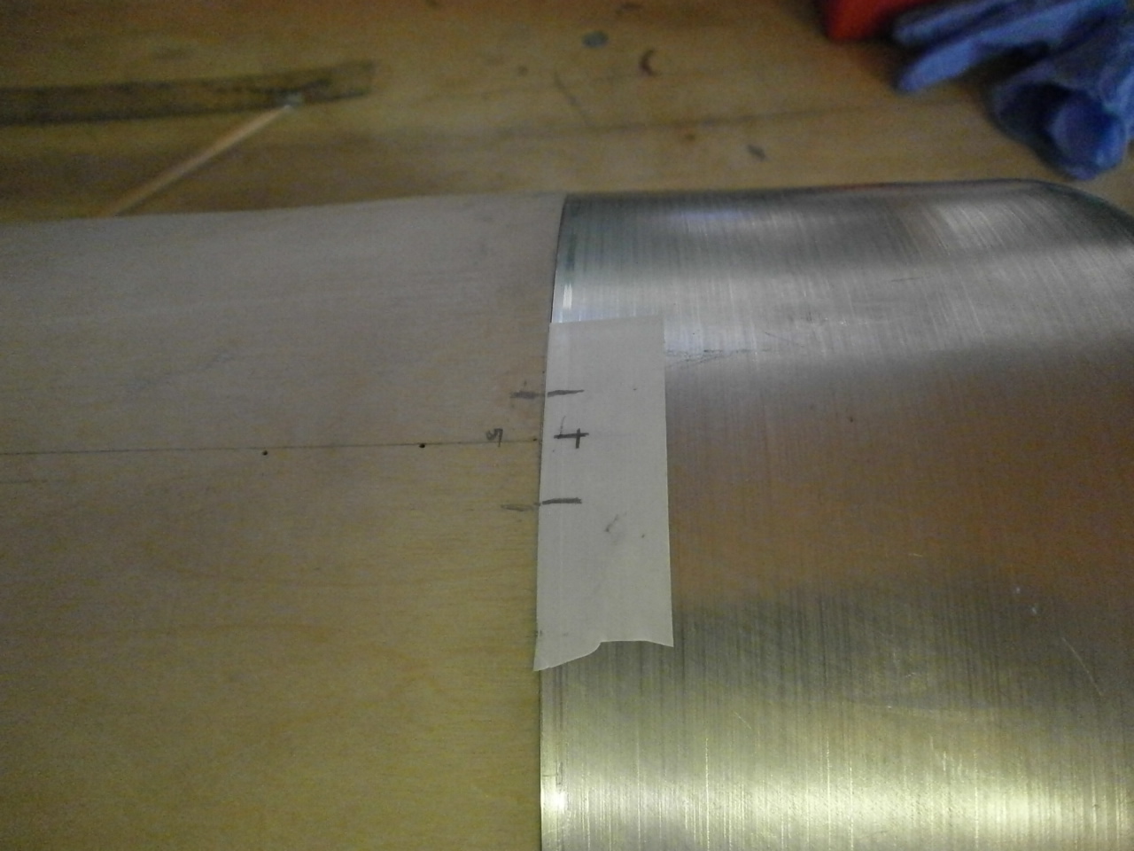
Next job is to mark out the locations where the fixing screws will be located onto the cowl. The screws need to be positioned so that they go through the centres of the mounting blocks. You can see from the second picture below that I have marked the edge positions of each block on to the fuselage. The cowl is held into place with tape located either side of the fuselage and a further piece of white tape placed onto the cowl where the mounting blocks are located. Once in place the lines indicating where the blocks are are carried onto the tape and the measurement between the two lines taken. A further line is then marked indicating the centre. The blocks extend out from the fuselage by 12mm so again a further mark is taken out from the fire wall to 6mm giving me my centre spot to drill the hole through the cowl and the block. This process is repeated for each of the 7 screw locations.
 |
 |
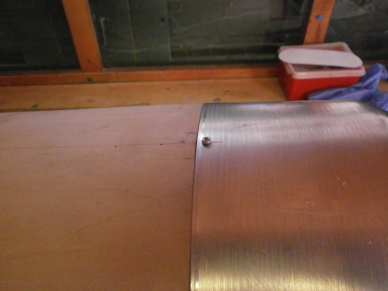
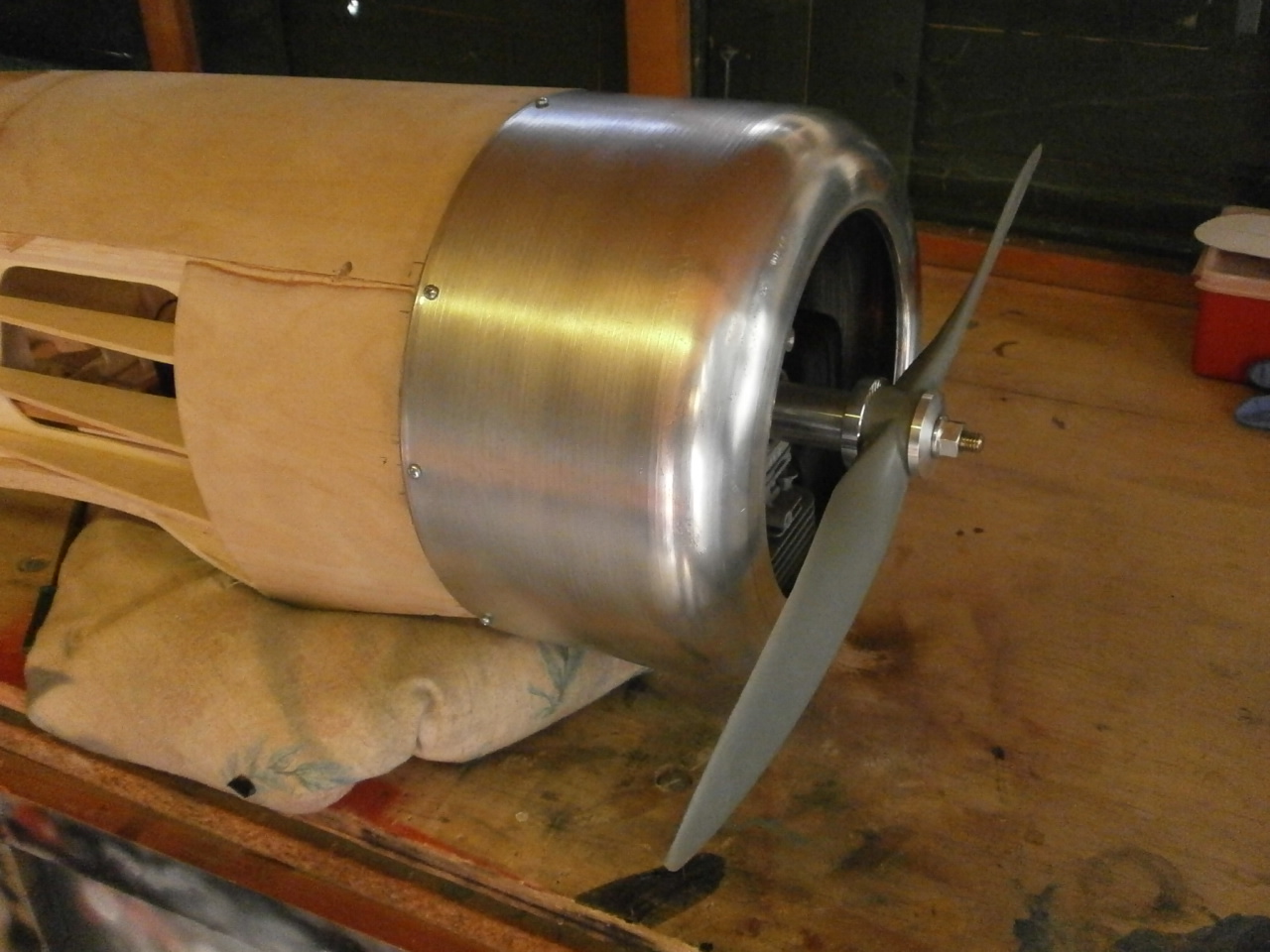
When drilling the holes I started with the top centre one first and then systematically drilled the next mark down on the left and then the right working from the top to bottom. Working like this ensures that everything remains square and no misalignment can be introduced. The last picture below shows the cowl now neatly secured into position.
 |
 |
Cowl installation
Stabiliser
Construction
Rudder construction
Wing Construction.
Fuselage page
Struts &
Control Linkages
Aileron installation
Sopwith page
Final Construction
Home page