
Fuselage Construction
| First attempt at
airbrushing pinup nose art
|
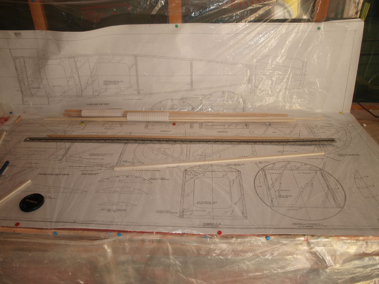
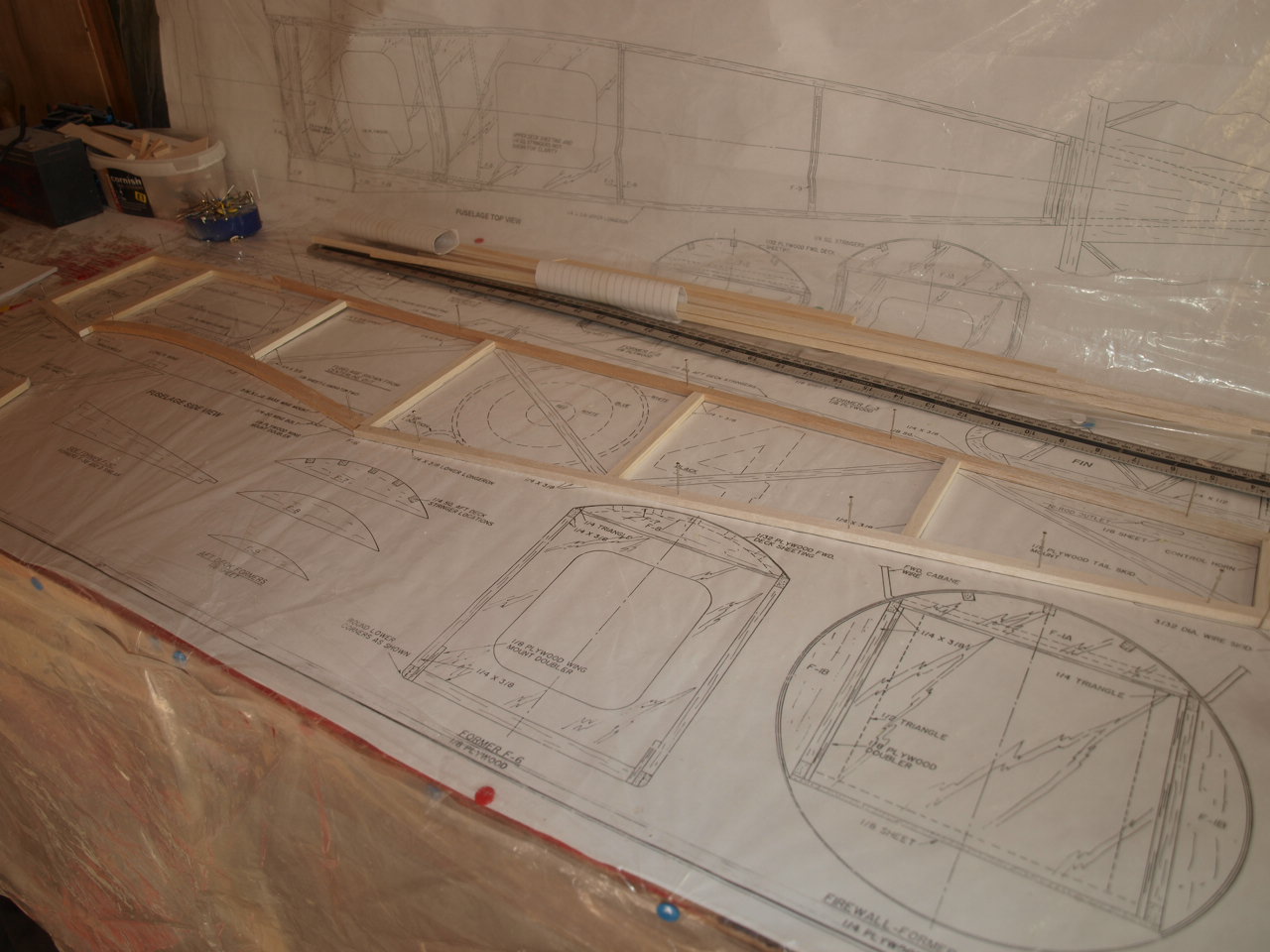
Having completed both wings to a stage as far as I could go before needing the fuselage to set them up and finish them off, I've now moved onto the fuselage.
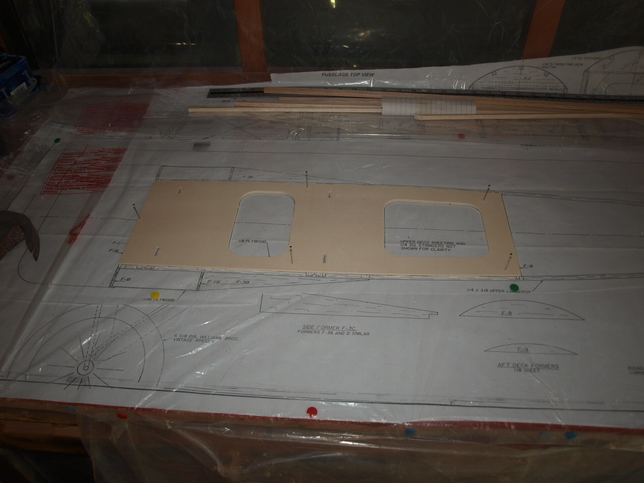
The first thing to do is to lay down the plans and cover with protective plastic.
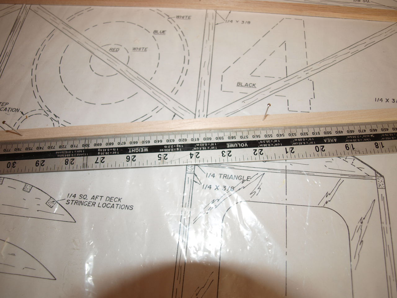
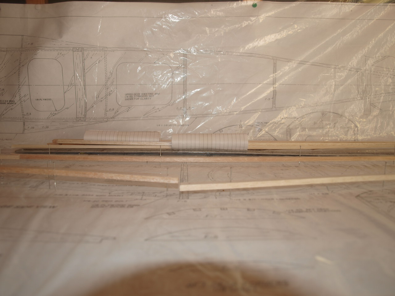
The next job is to locate the lower and
top balsa 3/3 x 1/4 longerons and locate them over the plan.
Again as we
did for the spars of the wings, a steel ruler was used to ensure these seated
squarely on the plan. See below.
 |
 |
The top longeron needs to be spliced together from two pieces of balsa and this was carried out as shown below and the join located between the F3 and F 5 formers. See below.
 |
 |
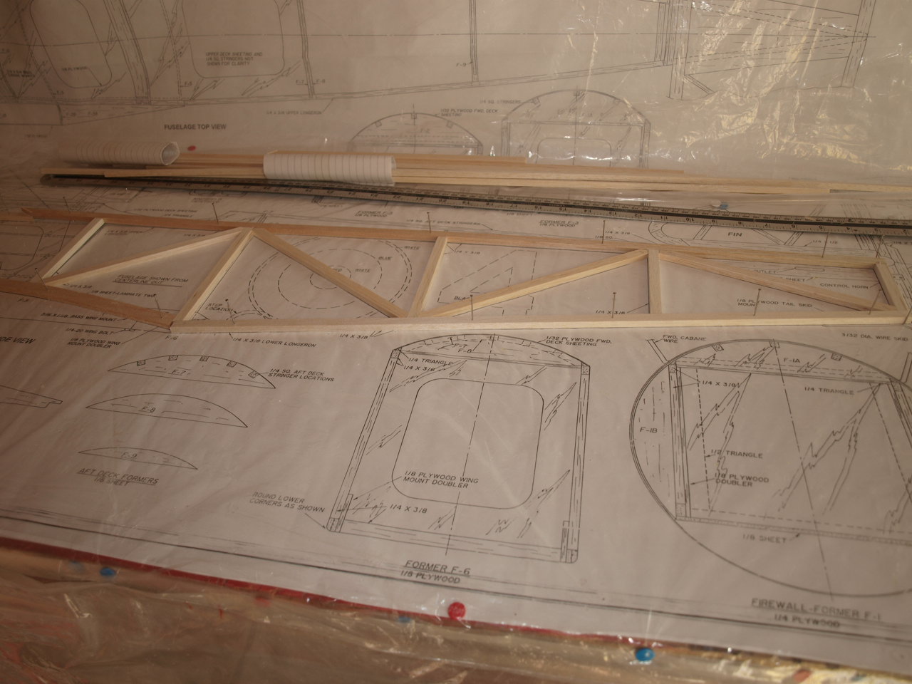
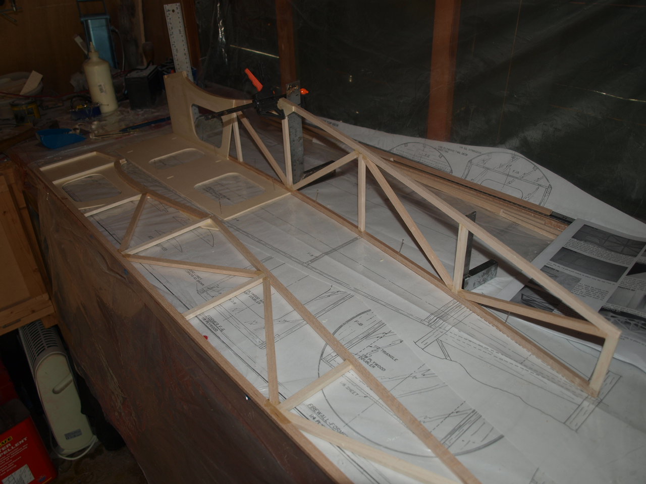
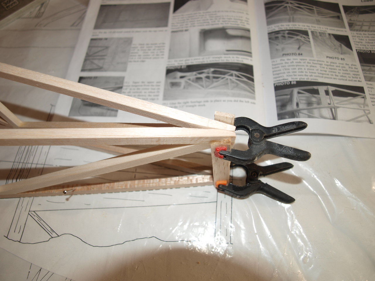
Next the vertical pieces are cut and glued into position. Again as previously explained, the longerons are raised of the board to allow the balsa used for the construction of these parts to slide underneath enabling the accurate marking ready for cutting.
 |
 |
Next the diagonals are measured and cut the same way.
Once happy with all the cut parts dry fitted they are glued into place.
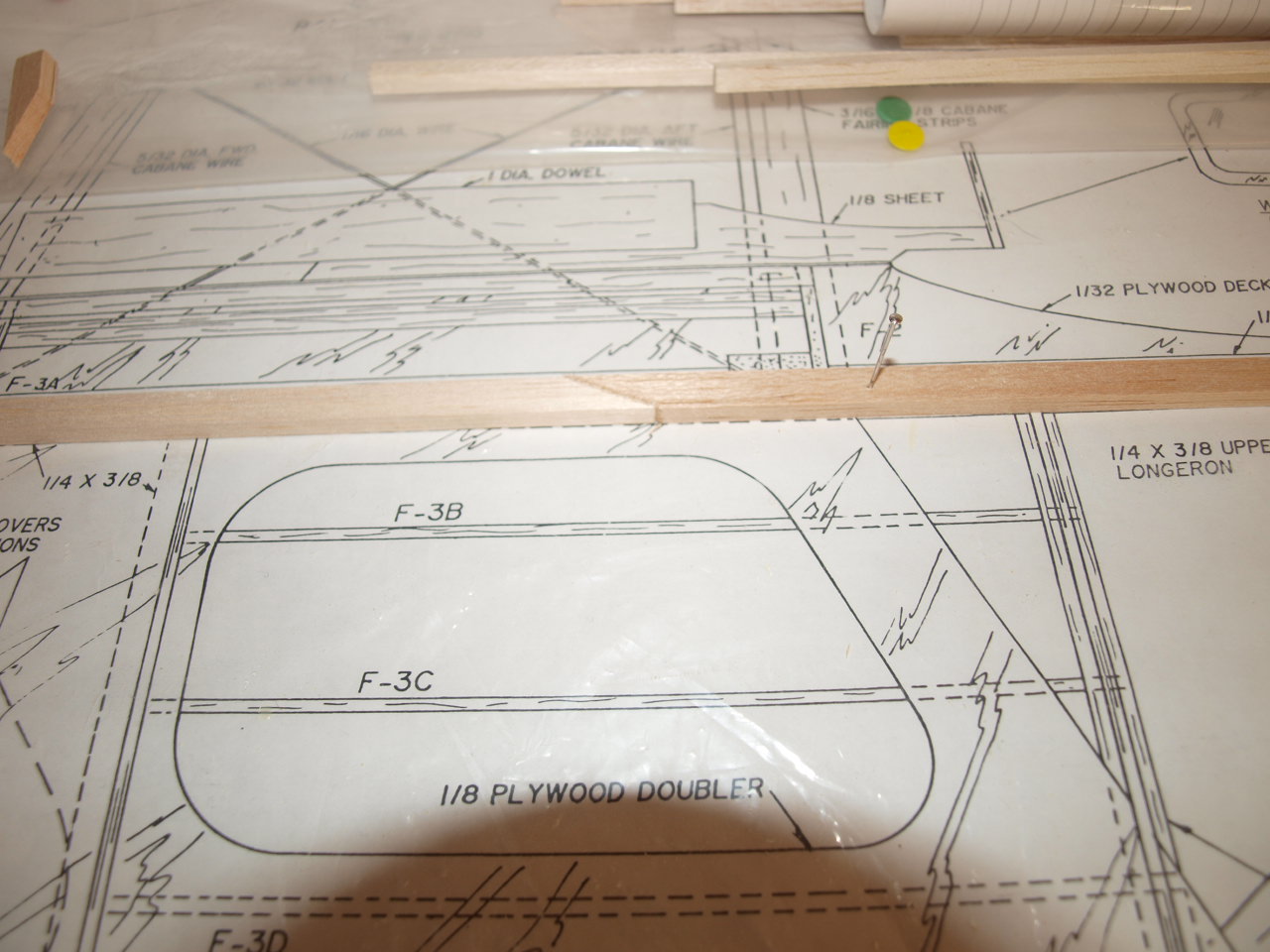
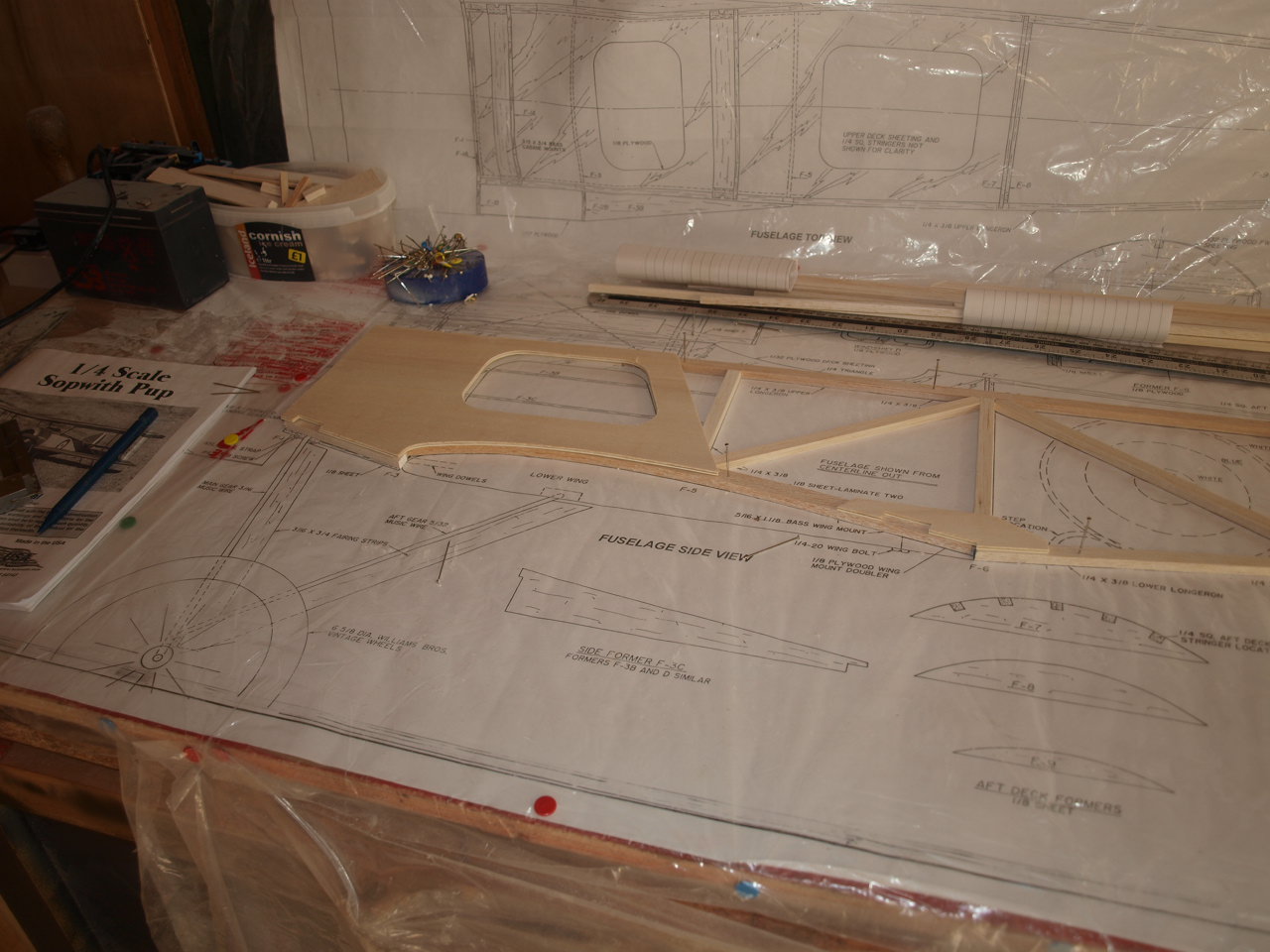
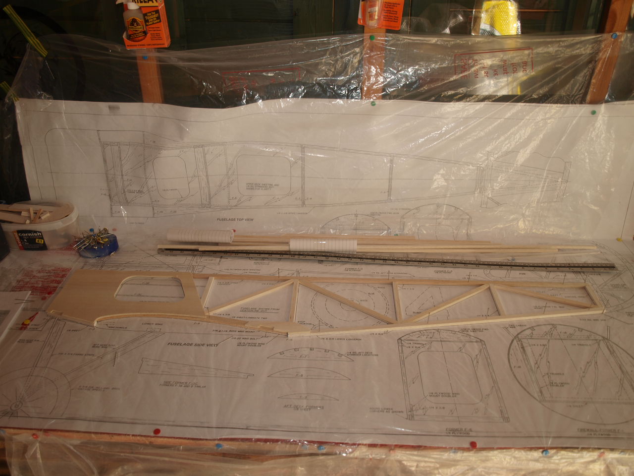
The next process is to locate and install the 1/8 plywood doubler. This is fitted over the balsa fuselage structure we have just built, but this doubler should be 1/8 below the top edge of the upper longeron.
You we also see in the second picture below that the wing mounting doubler has also been glued into place at this point.
The other fuselage side is made up exactly
the same way until you reach the stage of adding the doubler and wing mount.
As
we need a pair of handed sides the frame is removed from the board and reversed
and then the doublers glued into place giving us our handed pair.
 |
 |
The second picture below shows the crutch pined in place over the plan.
 |
 |
Once in place the left Fuselage side is offered up to the crutch with the doubler sitting on top of the crutch and the 1/4 x 3/8 longeron sitting against the crutch. Once happy that this all aligns correctly the assembly is glued into place. Before gluing the rear of the fuselage halves need to be tapered where they will be joined at the tail end. See first pic below
Once the tapers have been added, as just mentioned the left side can be glued into position. Second pic below
 |
 |
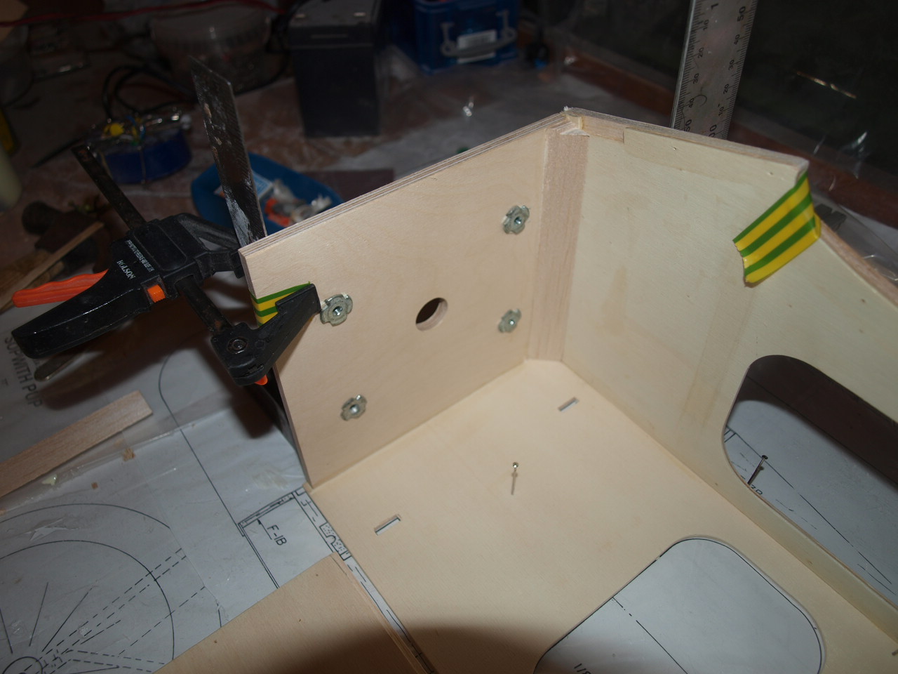
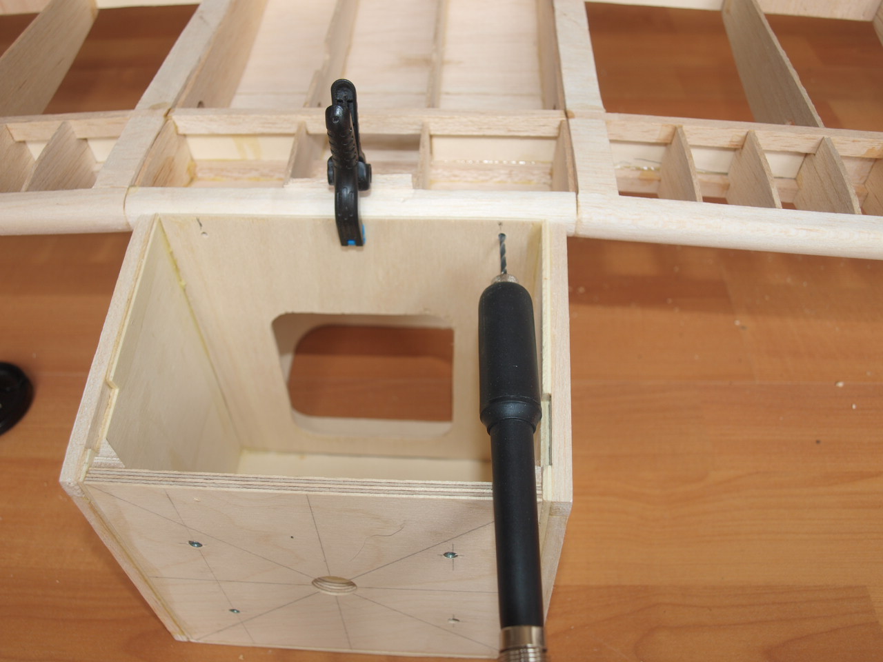
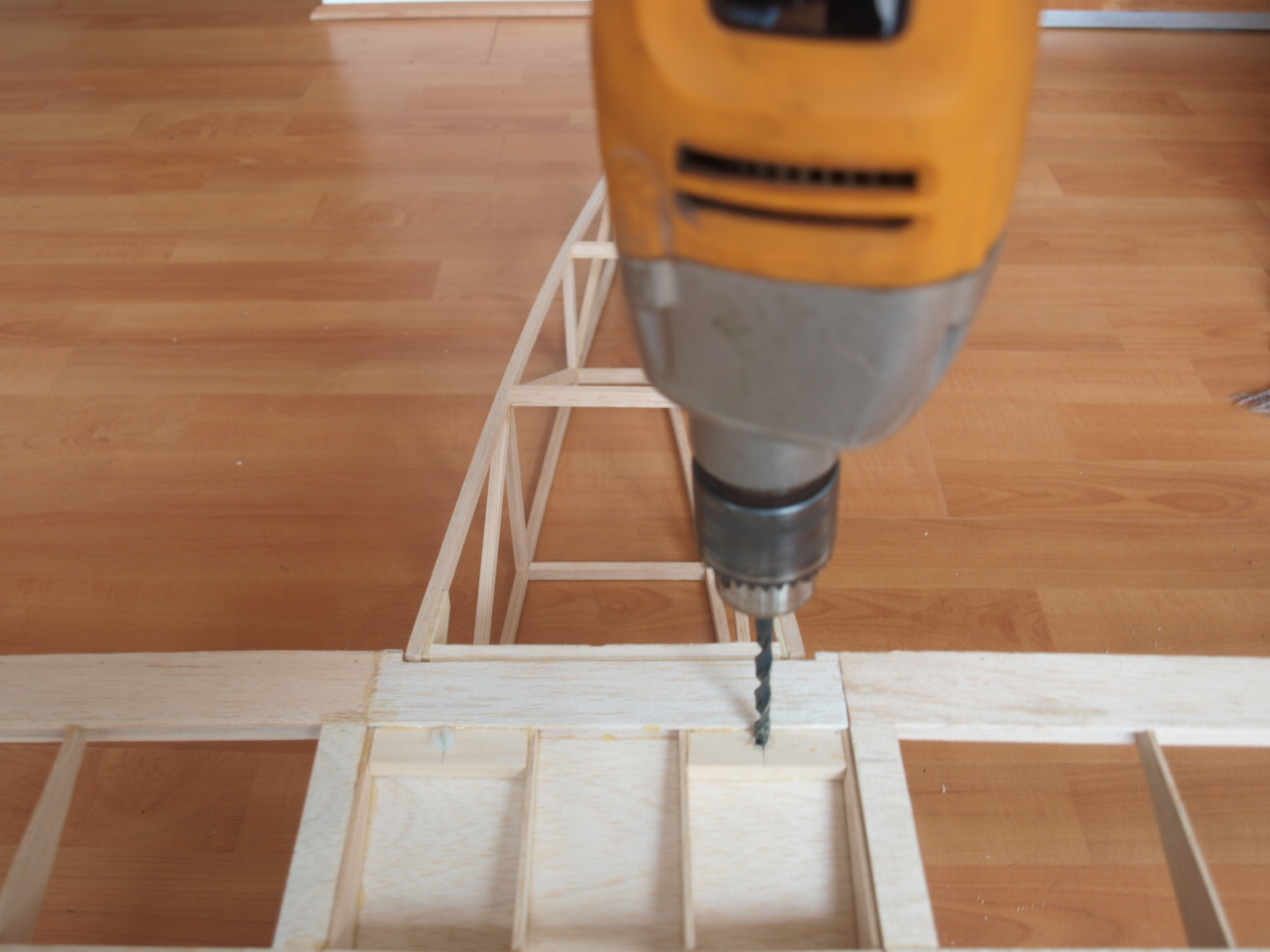
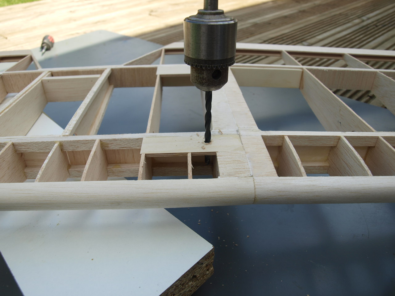
The next step is to glue into position the firewall. I decided to mark up the engine mounting locations before gluing in this part as it is a lot easier to do so at this stage and if you have a pillar drill as I do you are ensured of perfectly straight holes to locate you captive nuts.
Once this had been carried out the firewall was glued into place. Note the clamp and tape ensuring that this piece remains perfectly straight and square.
In picture two you can also see the 1/2 triangle stock piece in position adding additional strength to the joint.
The same procedure is carried out for the right fuselage side. See pic 3 below
 |
 |
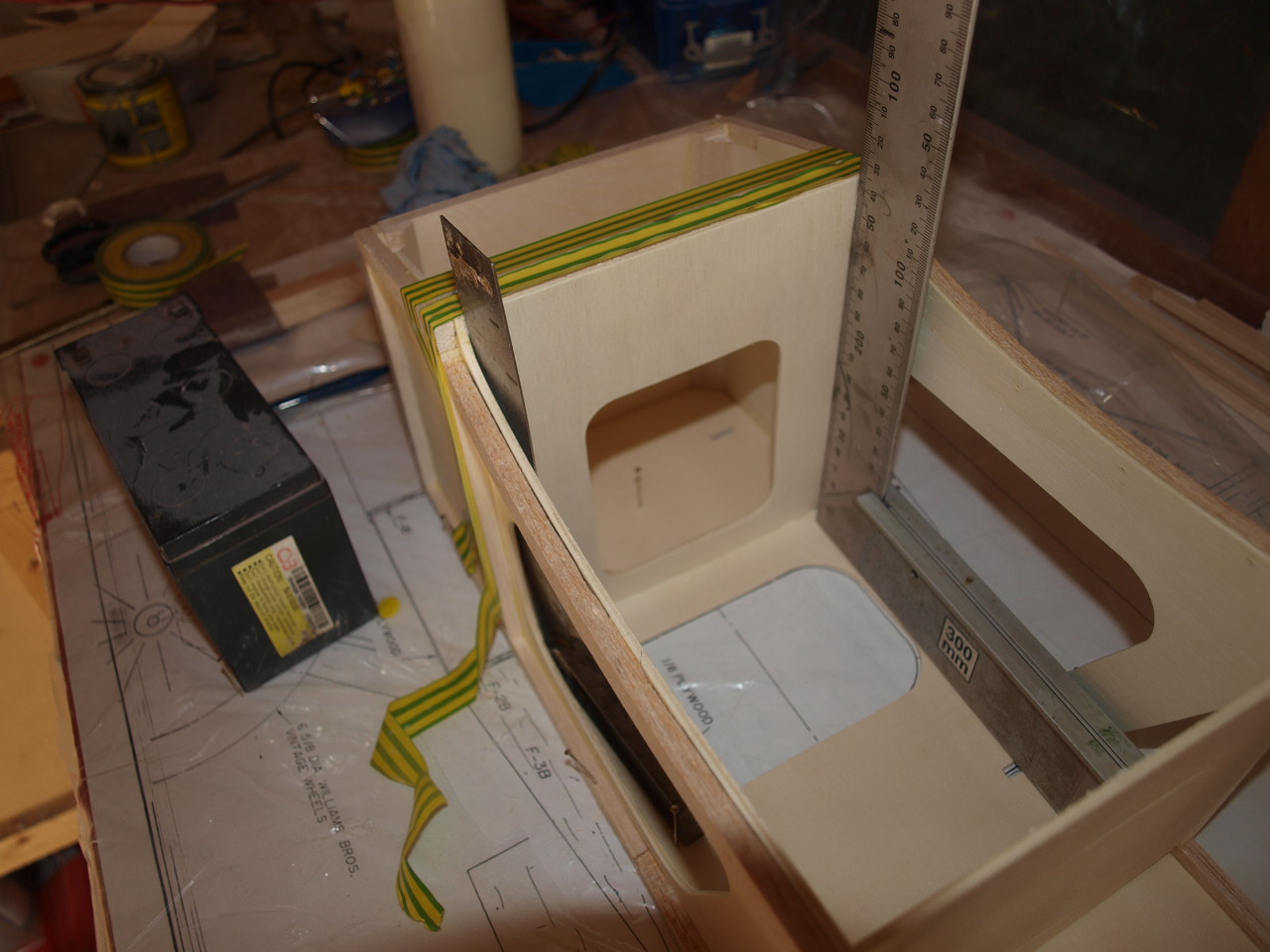
The next job is to locate and install the F3 former. Again note the use of set squares to ensure everything remains square and true .
 |
 |
Once the above has set, the next job is to install both the F5 and F6 formers. Before I could do that I needed to glue 1/4 x 1/4 stiffeners to he bottom of each former
 |
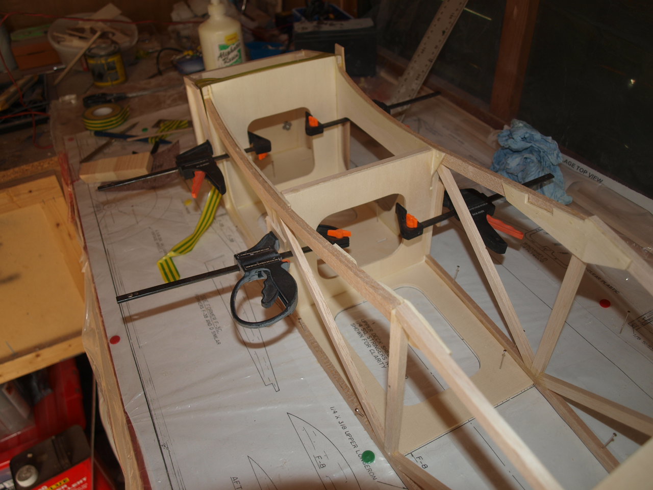 |
Once set the formers where located into
position and glued, kept in place by the use of clamps. Note to avoid damaging
the balsa frame scrap pieces of balsa where used between the clamps and the
frame
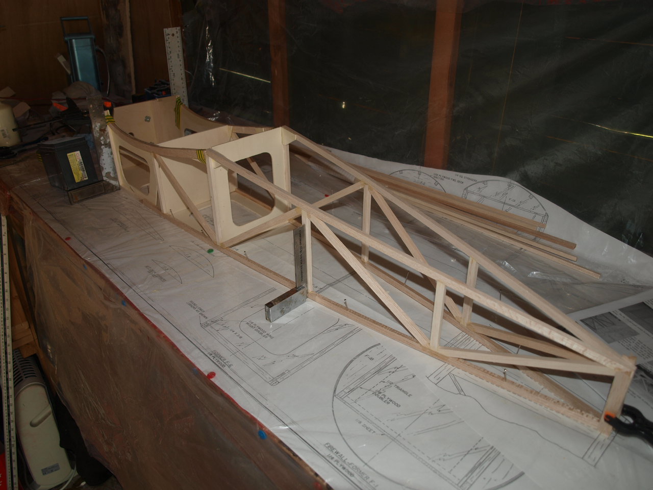
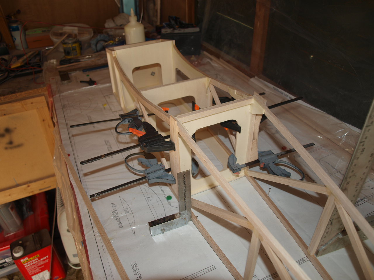
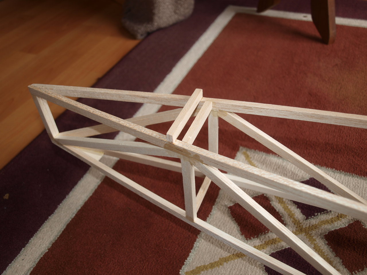
Once set the rear of the fuselage is pulled together making sure to check that everything lined up with the centre line
on the fuselage plan and once happy with
the dry fit glued and pined into position.
 |
 |
The only thing left now to complete the basic structure was to add the cross pieces of 1/4x 1/4 balsa that where glued and clamped into position whilst checking with a set square that the sides where perfectly square.
 |
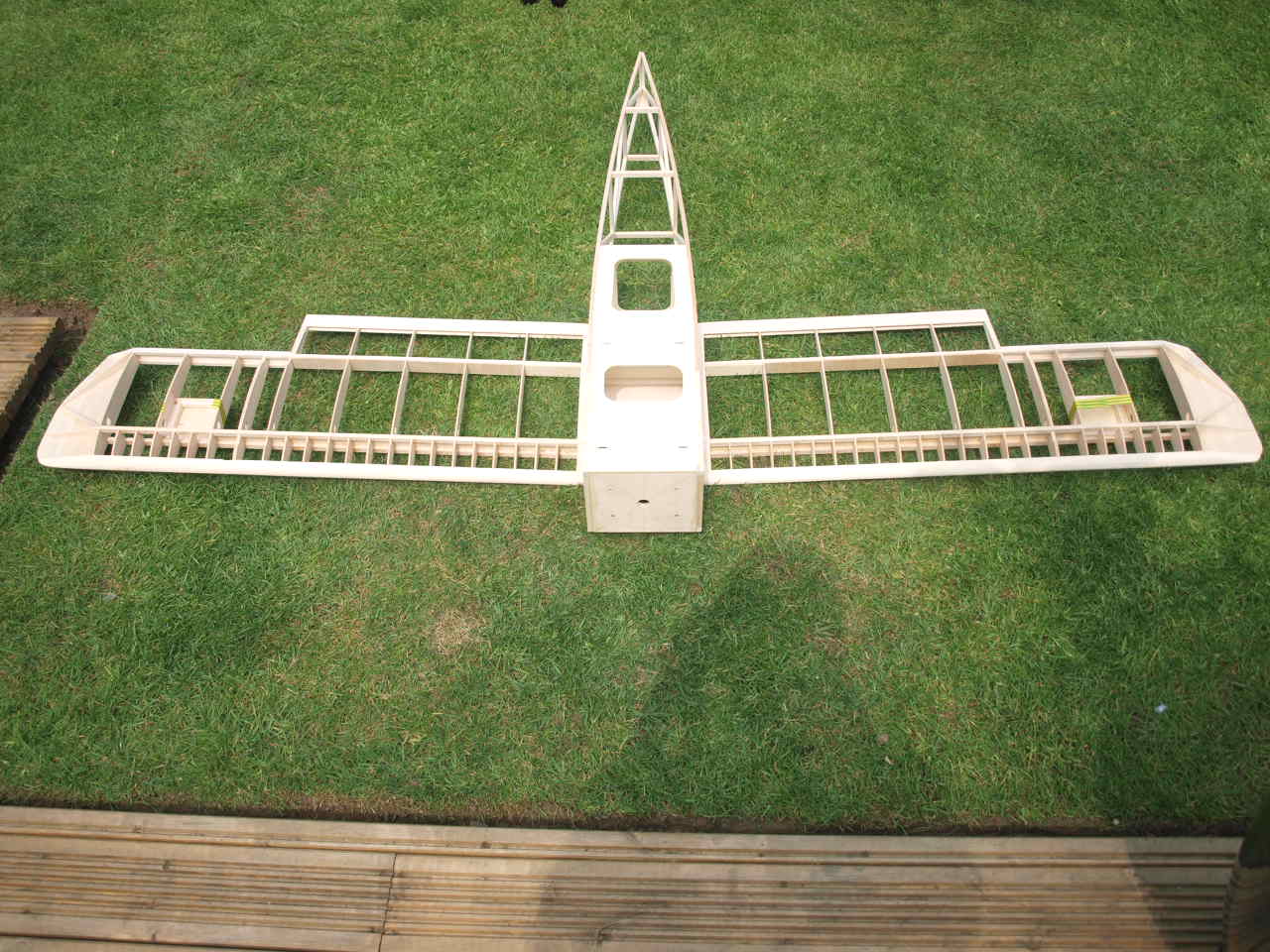
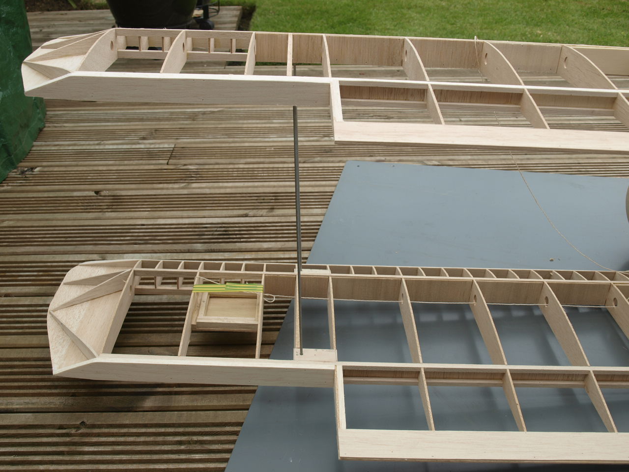
Before any further work can be carried out on the fuselage the lower wing mounting system has to be setup and installed see below. |
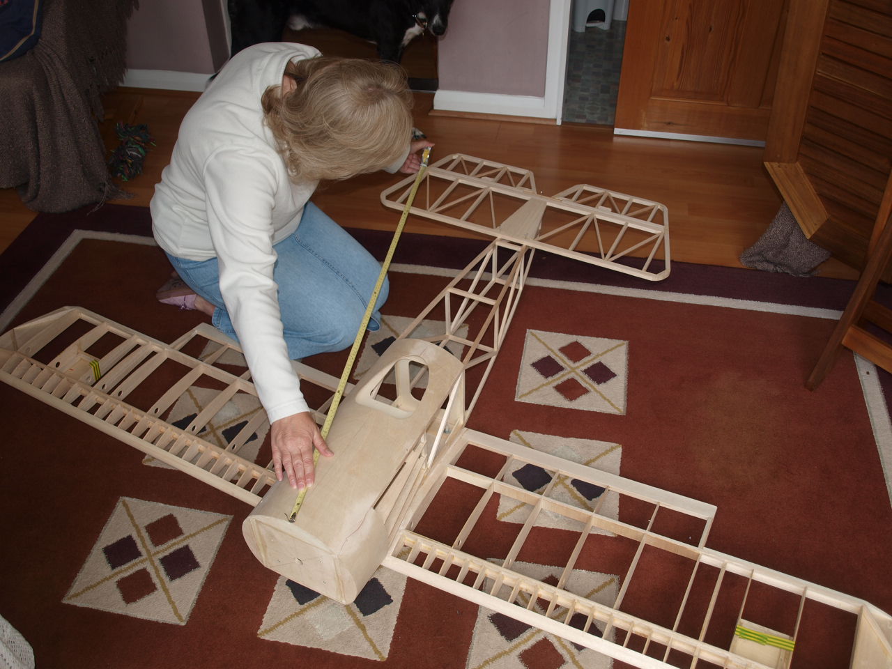
The picture below shows the fuselage and the wing in place.
The next step is to measure from each wing tip to the rear end of
the fuselage obtaining an equal measurement from each side.
Once happy that
everything is square the wing can be marked ready for placement of the wing
fixing dowels and screws.
The second picture shows the fuselage now inverted with the wing in position whilst taking care to ensure our marks placed earlier remain in their correct positions and the wing square with the fuselage..
You can see in this picture that the locations of the dowel holes have been marked on the F2 former at the measurements given in the construction manual.
The wing is clamped into position ( it is helpful if you also have someone help keep the model firm throughout the following stages) and the wing fixing dowels holes drilled through both the F2 former and the leading edge of the wing and through to the front spar dihedral brace.
 |
 |
The following two pictures show the holes in the F2 former and the now located dowels inserted into the wing.
 |
 |
With the wing now relocated into position see top right
picture we can concentrate on installing the wing bolts.
Again following the construction manual measure out the locations of the wing
bolt holes. You can see in the picture the marks will fall onto the hardwood
tapered blocks that we installed at an earlier construction stage.
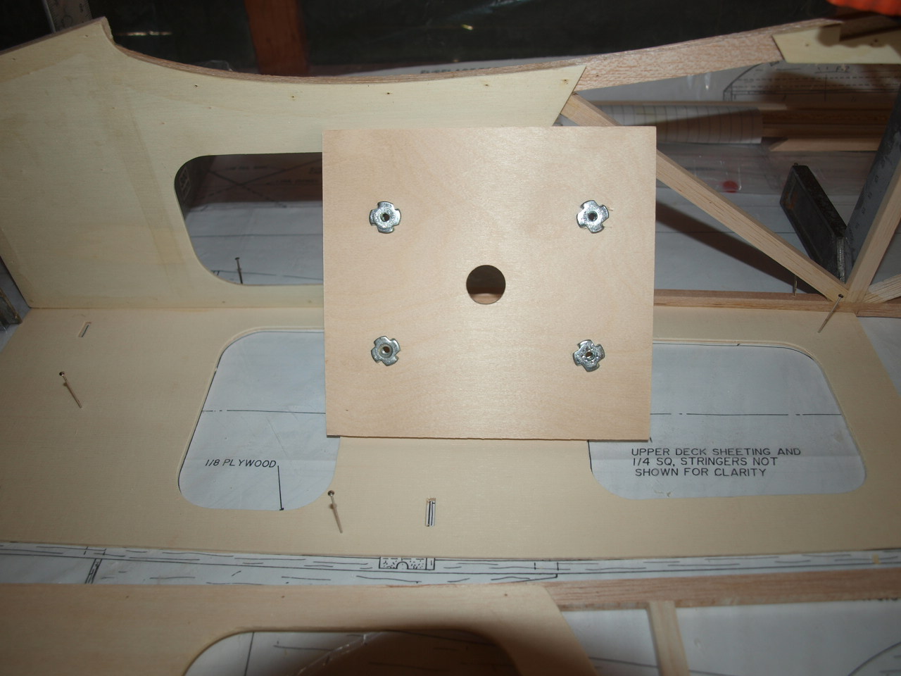
Once happy that everything lines up drill through the wing and into the wing mounting plate of the fuselage.
Now we can remove the wing and install our captive nuts to the fuselage wing mounting bracket.
You can also see in the second picture that I have placed the front bottom sheeting in place, now that the dowel holes have been placed and there is no further need to access the F2 former from the front.
 |
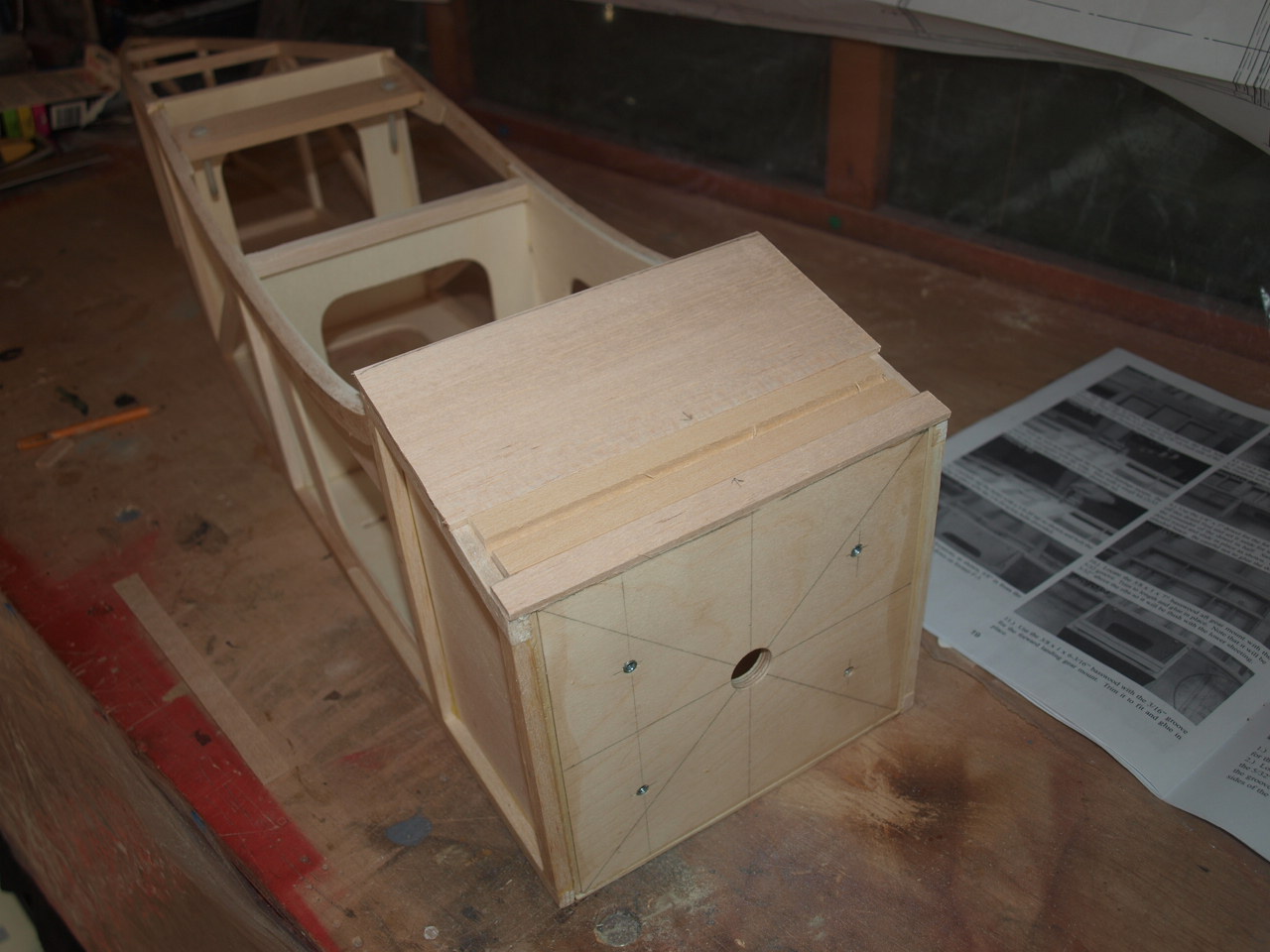 |
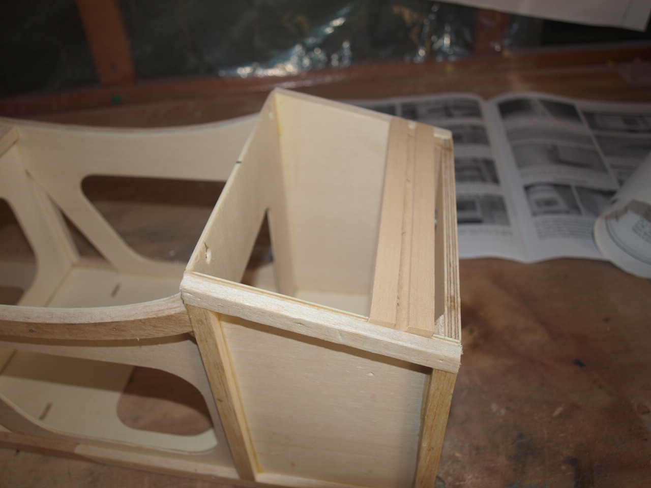
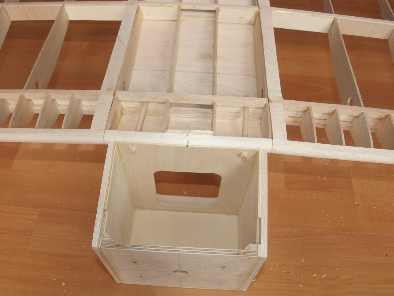
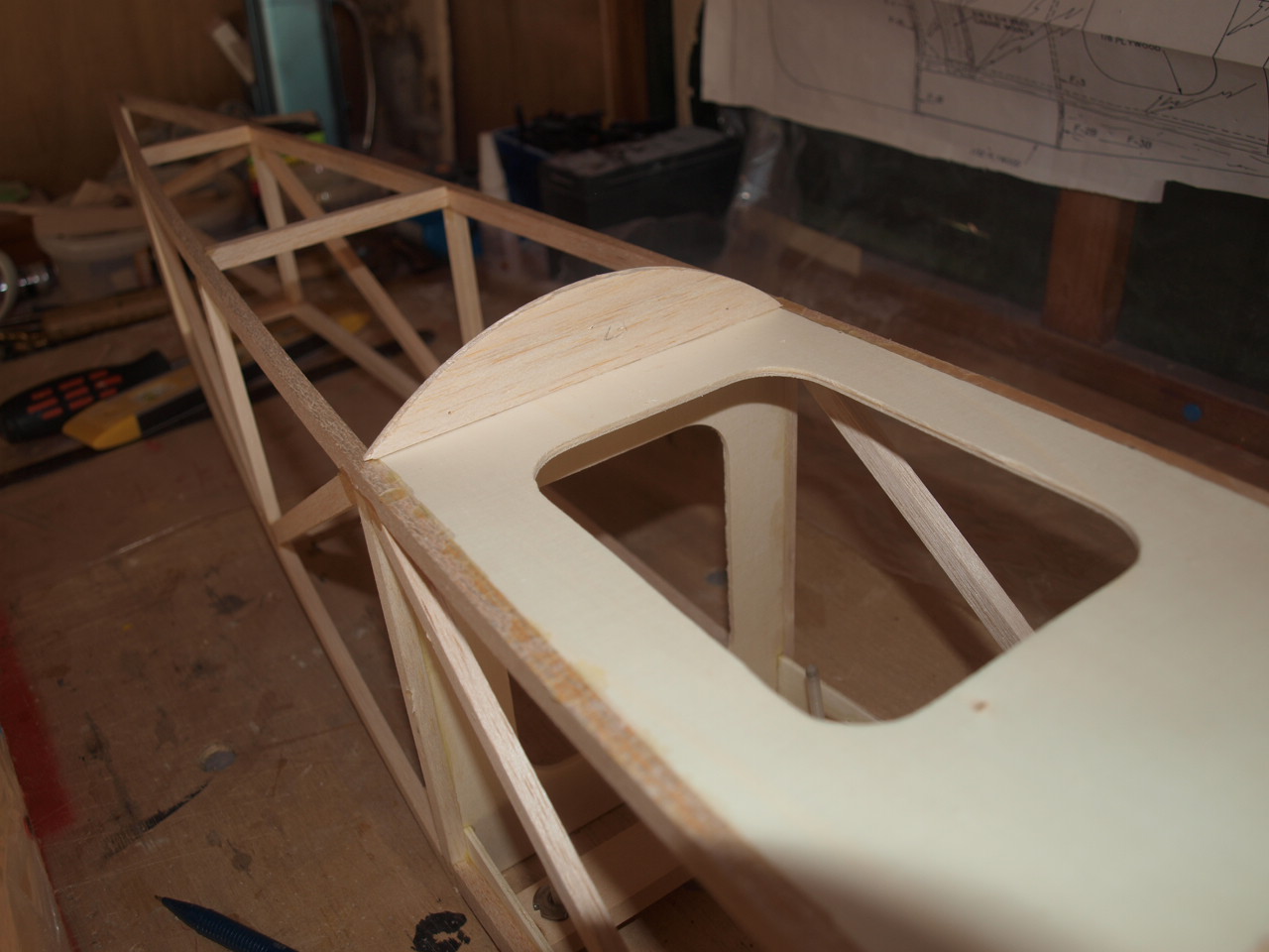
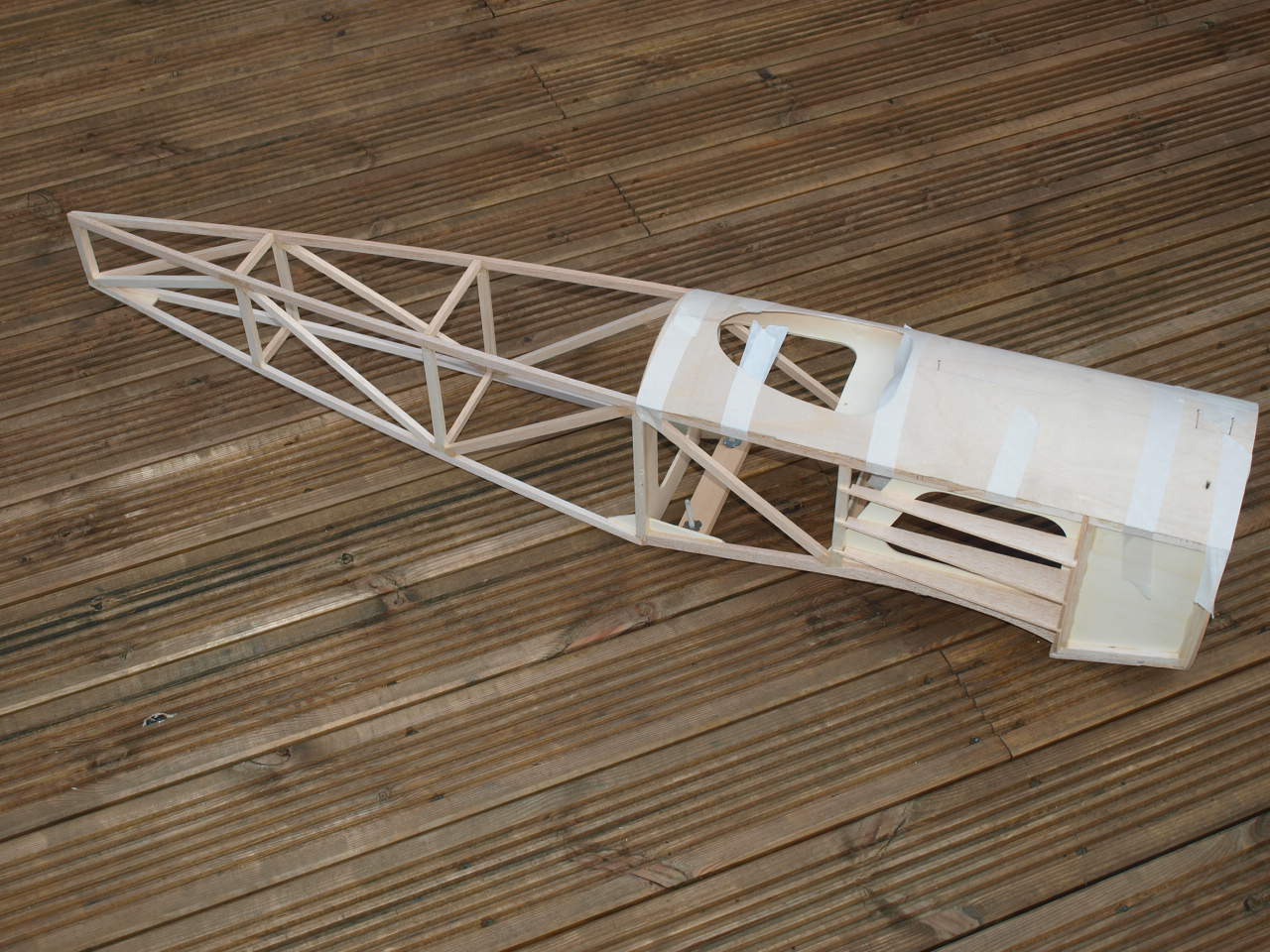
The next job is to locate and install the front top
decking formers and stringers ready to accept the ply decking sheet.
Also note the two ply blocks one towards the front of the fuselage and the
other just before the cockpit area. these are what will hold the centre wing
struts ( all will be revealed later)
 |
 |
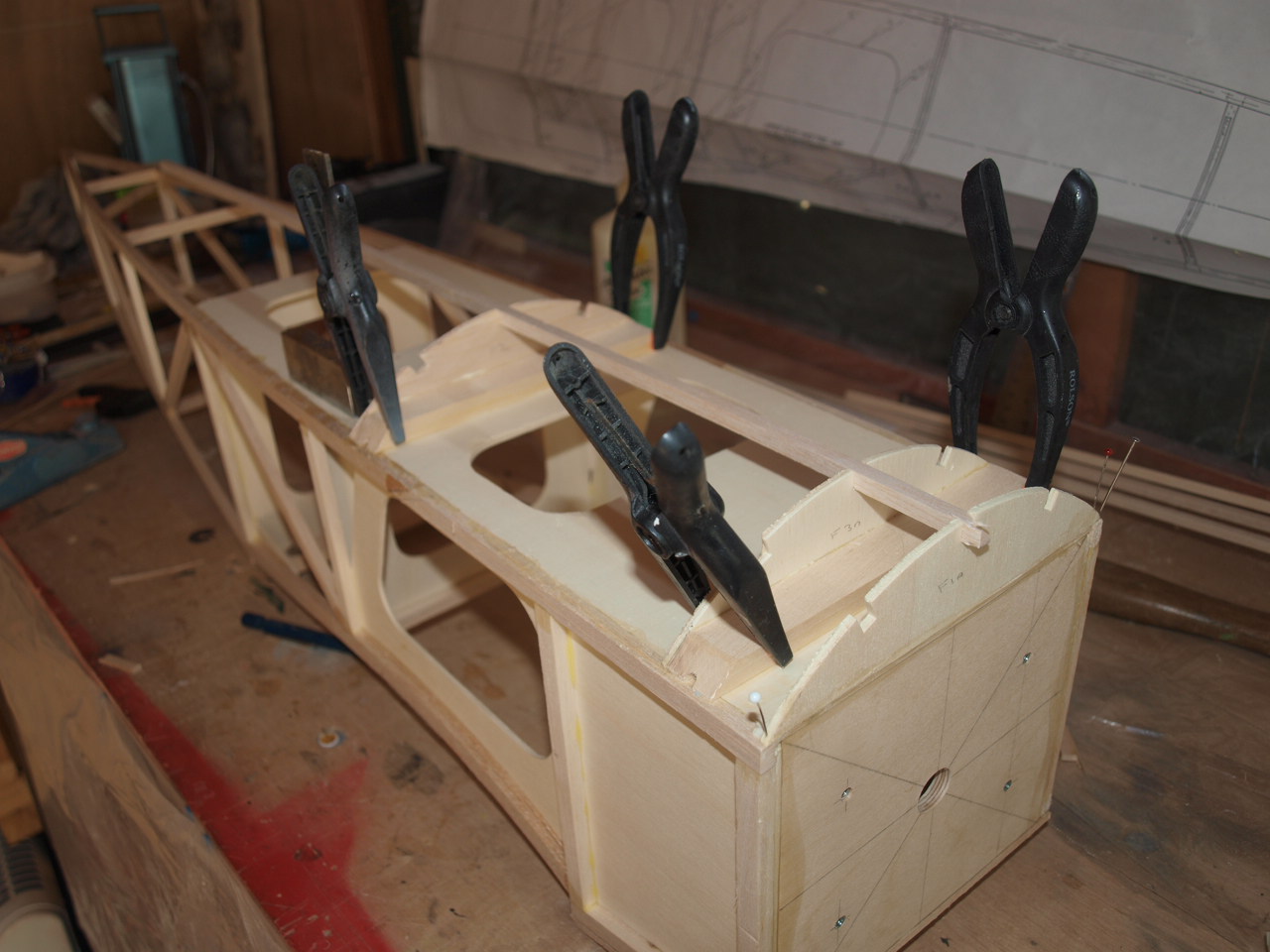
The next picture below shows the back decking former in place ready for when the ply decking sheet is placed
The fuselage is now placed on its side and the side fuselage formers glued into position, again ready to receive the ply sheeting.
 |
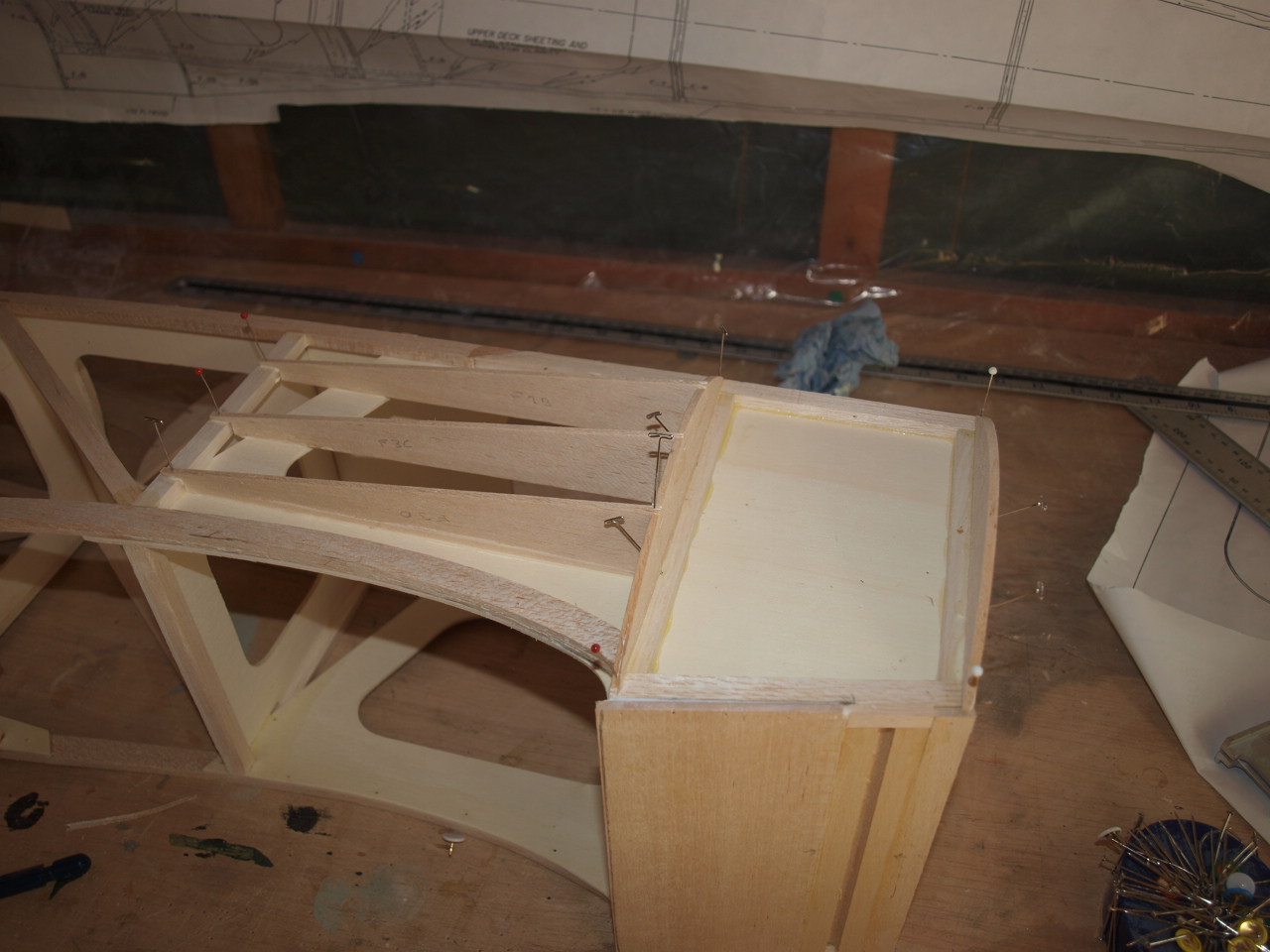 |
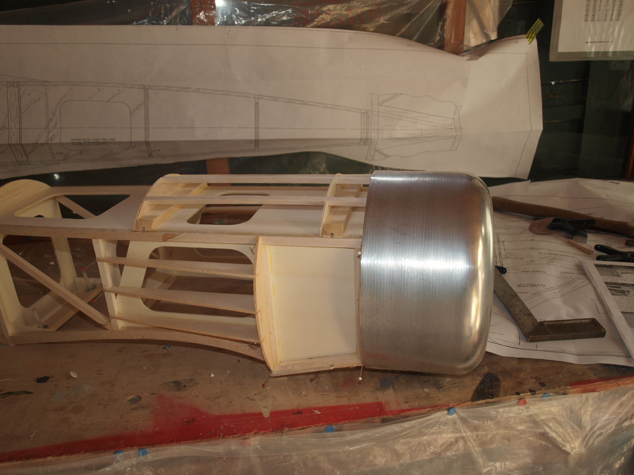
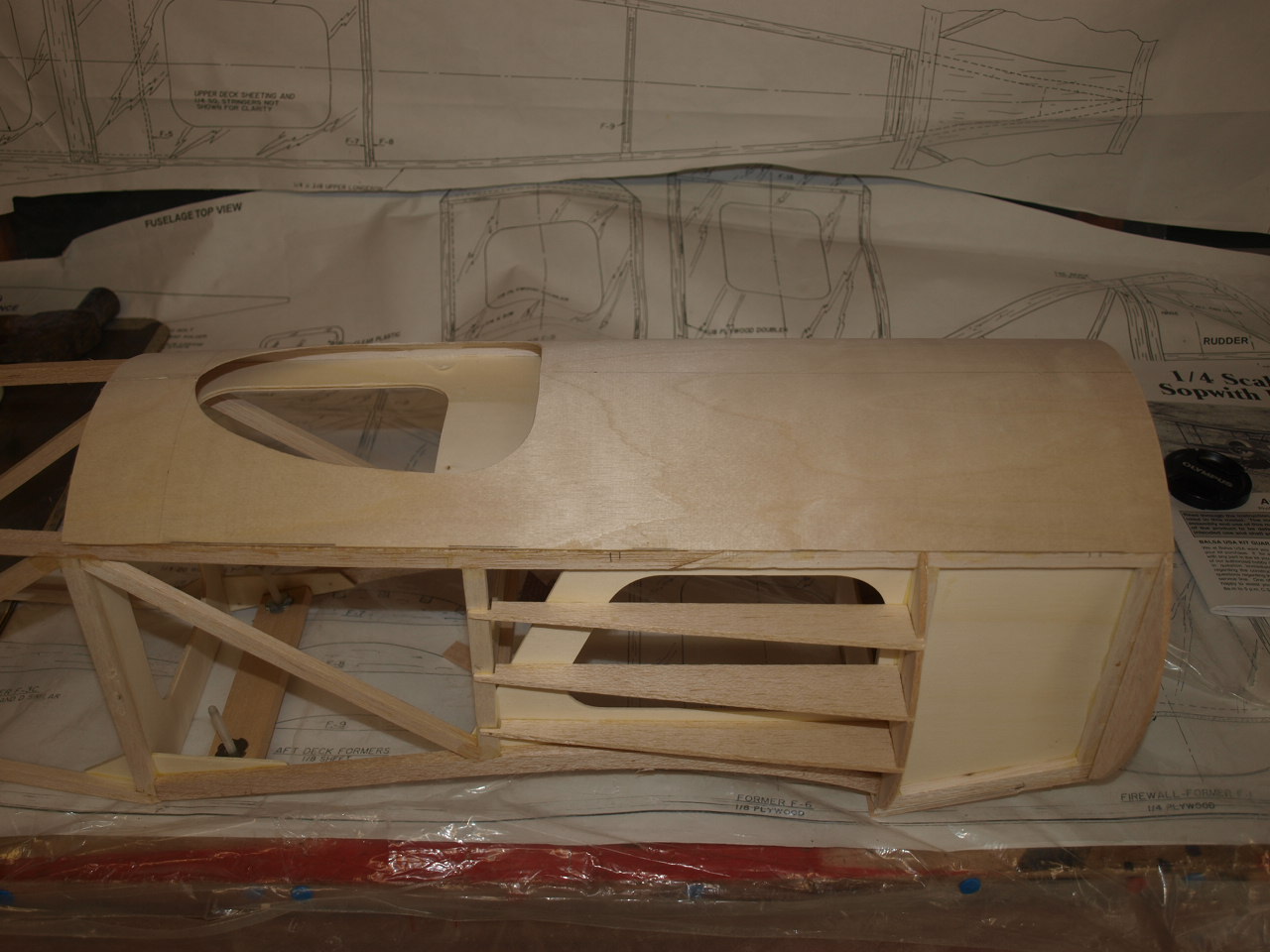
Sorry just could not resist seeing what the fuselage would look like with the cowl in place.
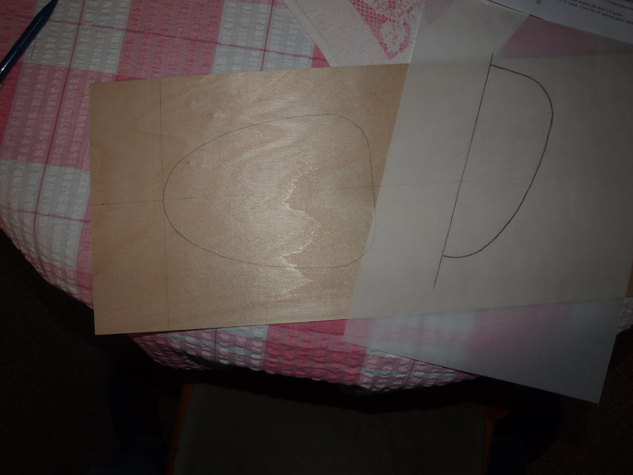
The next job is to mark out the cockpit cut out on the ply sheeting. The way I have done this, is to trace the cockpit template from the plans and then transfer the image to the ply.: see second picture below
 |
 |
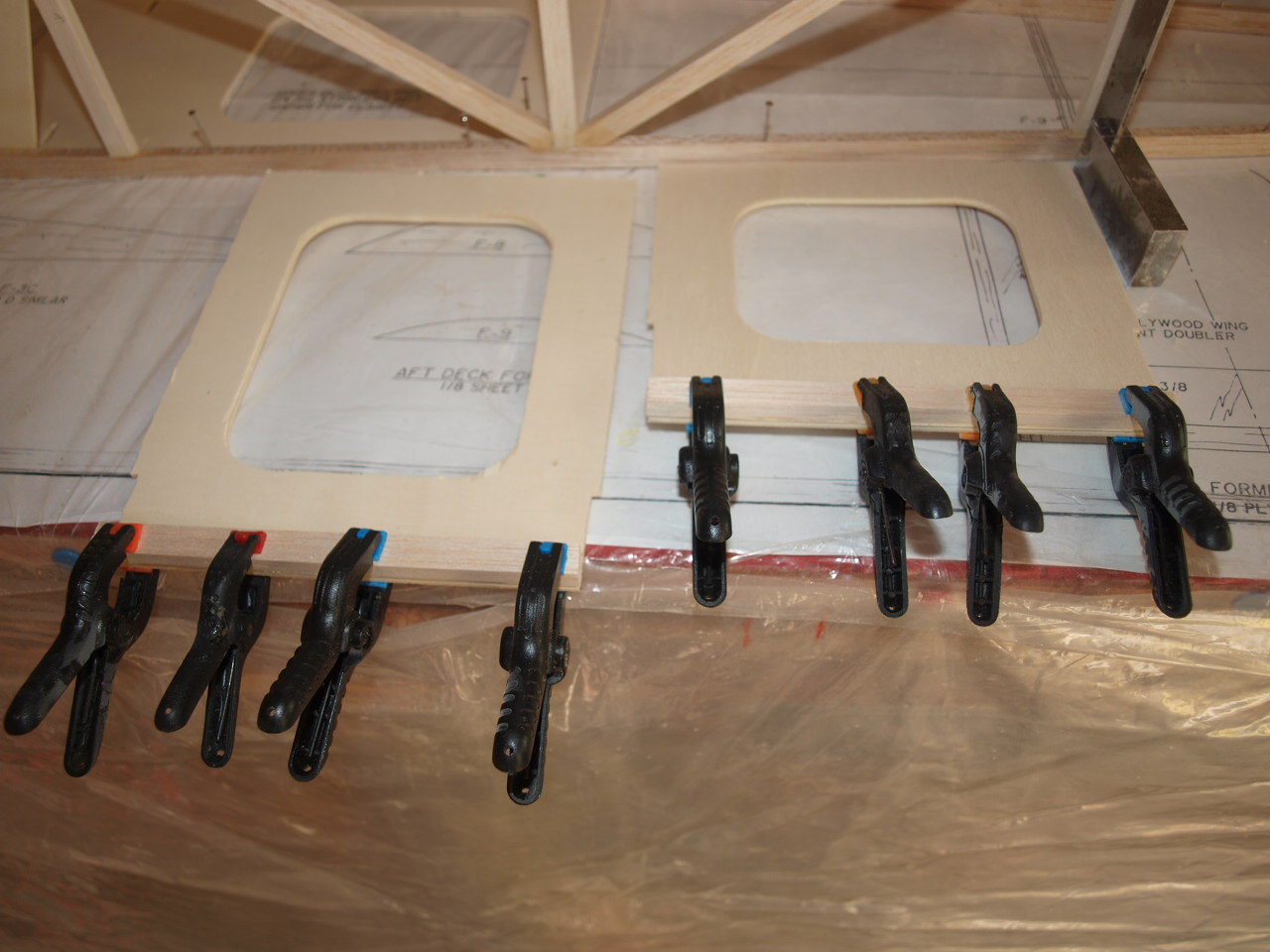
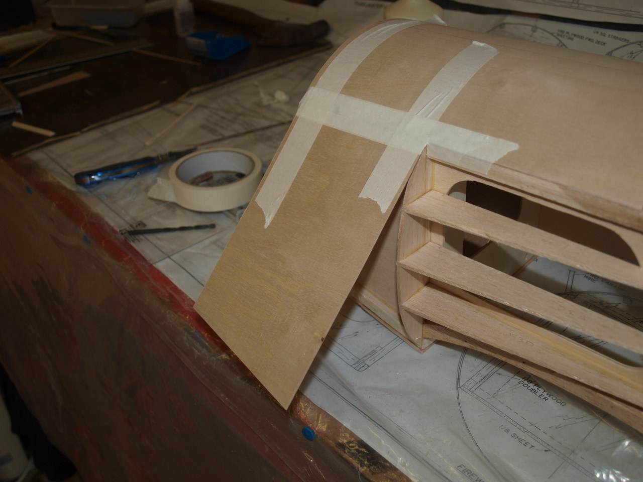
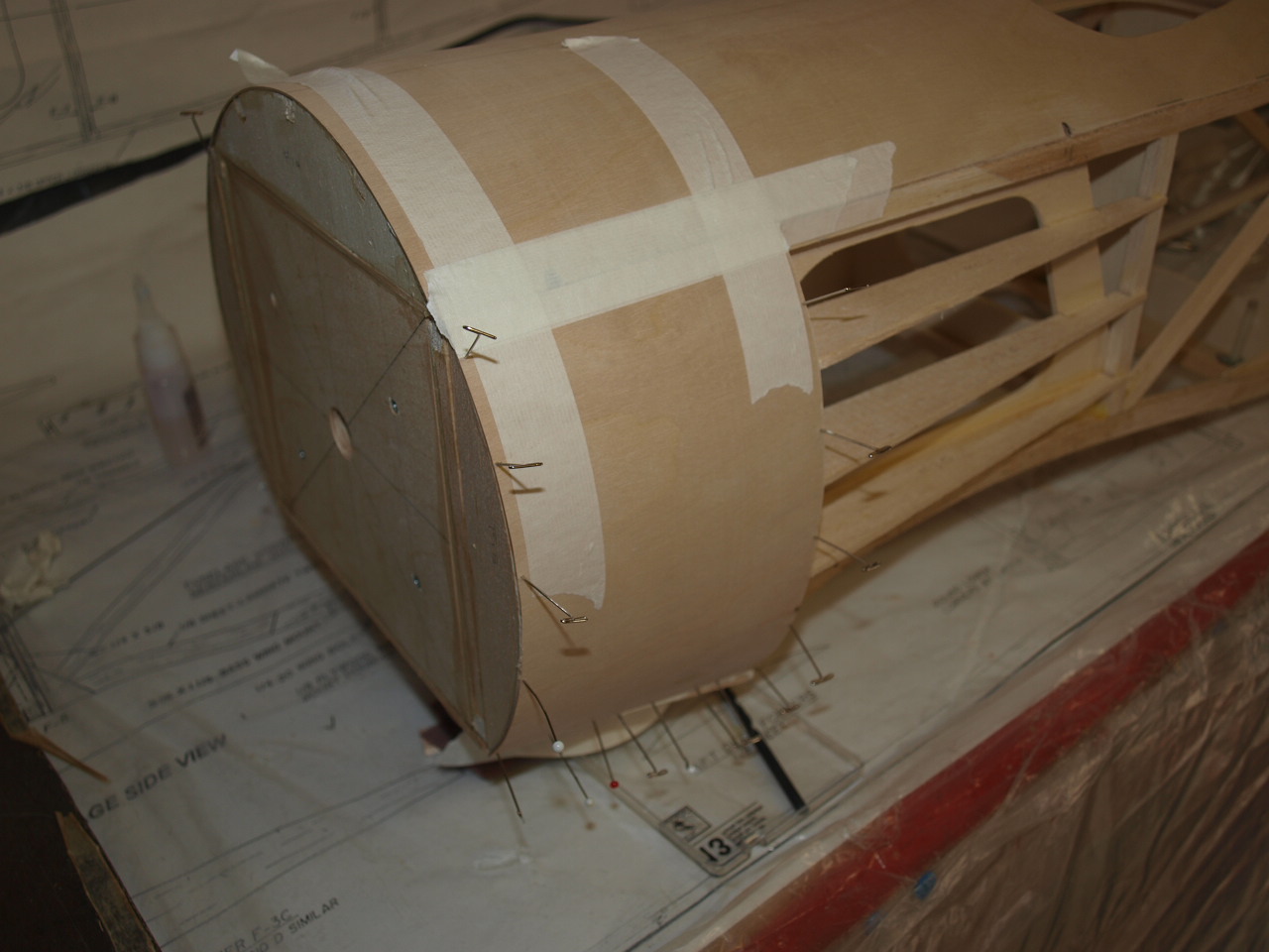
Once the cockpit has been cut out the ply is glued pined and taped into place. Again it is a good idea if you have someone help you with this as it is a little tricky getting everything lined up and secured into place.
Second picture showing decking with pins and tape removed.
 |
 What a silly boy an I. As you can see I've cut the cockpit cut out the wrong way around. This has since been removed and a new ply sheet re-cut this time with the cut out facing the right way. |
The next process is to install the side ply sheeting. this is done in a similar way to the top decking, but as you can see in the first picture below I have butted the top edge of the ply to the top decking sheet and only glued this into position to start with and left to dry. Once dry the rest of the sheet is glued into position and held in place with tape and pins until dry.
 |
 |
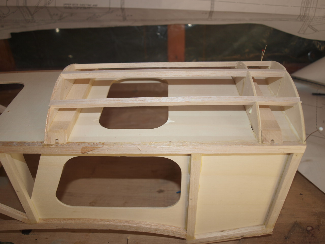
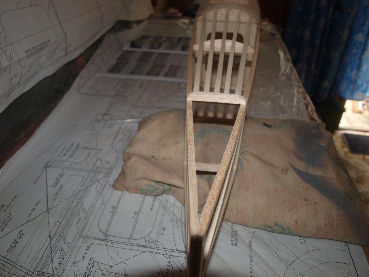
Before we can place the top rear stringers to the fuselage
the Stabiliser needs to be placed into position and squared up.
This process is carried out in a similar manner to the wing mentioned earlier. The only difference
is, instead of the measurements coming from the rear fuselage
the are taken from the front. See below
Once all lined up we can install the stabiliser stop
 |
 |
Now the top stringers can be put into place.
 |
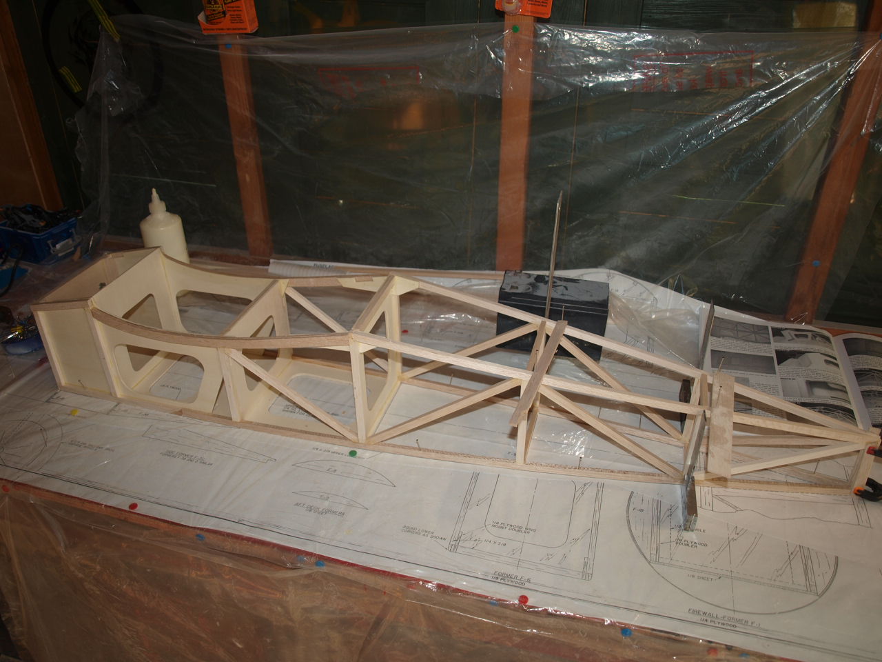
Now that the fuselage structure is complete I
can move onto making up the cabane struts.
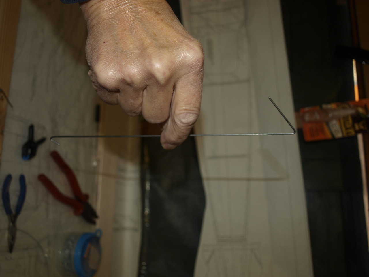
The first thing to do here is make up two identical strut gigs from a pieces of
11inch x 1/4 x3/8 balsa.
As per the instruction booklet 5/32 holes where drilled into each piece at 2 1/2
and 9 1/2 from the end of the balsa. This is then placed on the strut wires as
shown in the first picture below.
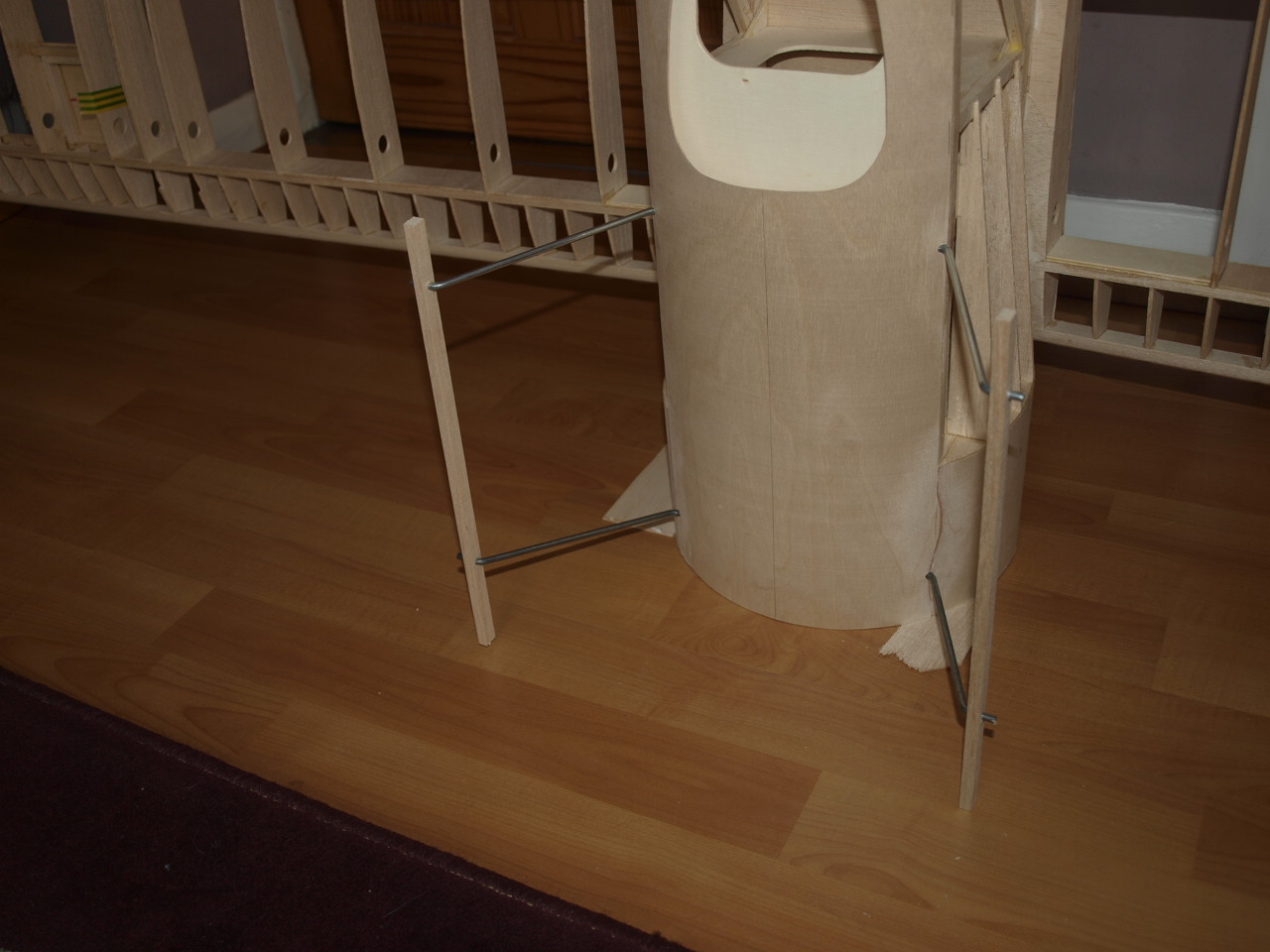
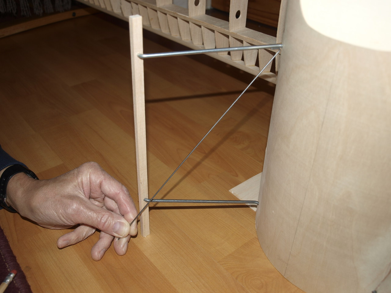
Before I can start measuring up x
soft wire pieces, the lower wing was attached to the fuselage and the fuselage
then stood on its firewall, on a level surface.
The wing is then measured at each
wingtip to to ensure that the wing is parallel to level floor surface. If not it has to be shimmed up under the firewall until the wing is.
Again see picture 1 below.
Once this has been achieved the jigs are then pushed to the level floor surface and a square used to ensure that the aft cabane wire is at 90 degrees to the upper longeron of the fuselage.
Once I was happy that all was square I could
set about making the x wires. I must say the the method described in the
manual for working out the lengths and bends needed for these, confused the hell
out of me, so I asked a fellow club mate to read the manual and he to got as
confused as me.
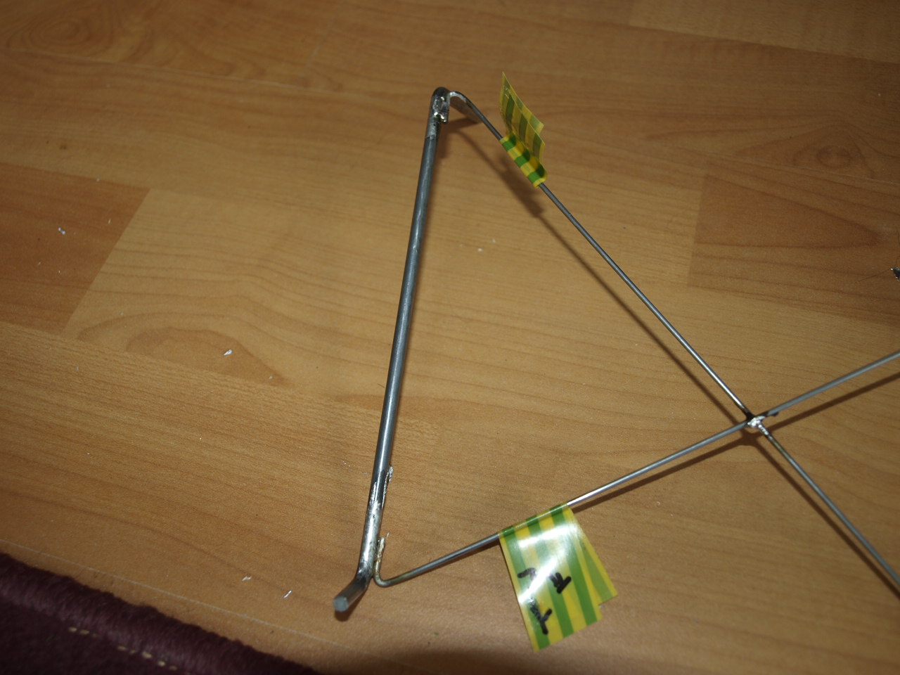
In the end I decided to do things my way which involved bending the first end of
the wire to shape and then offering this into its position (see pic 2) and
then mark the other end to where the other bend needed to be. This was the bent
and hay presto we have a perfect fit. This was then done for the other cross
wire that indecently was slightly shorter as per the plan.
 |
 |
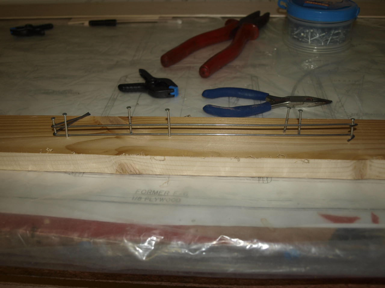
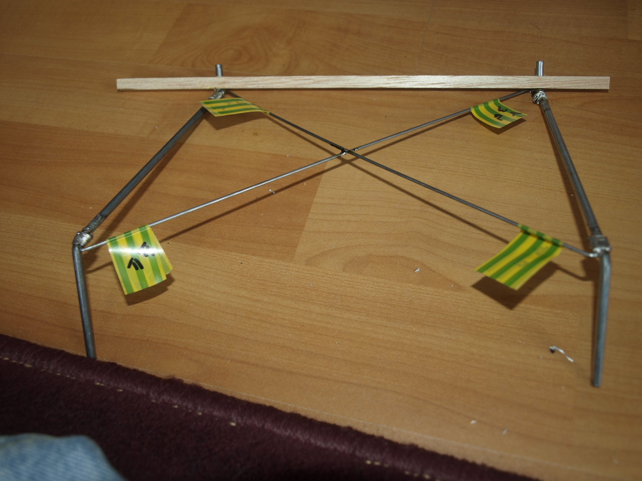
To ensure the other side was an exact match the wires where laid onto a scrap piece of old pine strip and nails taped into place at the bends with a couple either side of the wire down its length to stop any bowing (pic 2)
Once this was completed the wires for the other side could be bent on this gig giving me an identical set
 |
 |
The next job was to tin both the struts and cross wire with solder
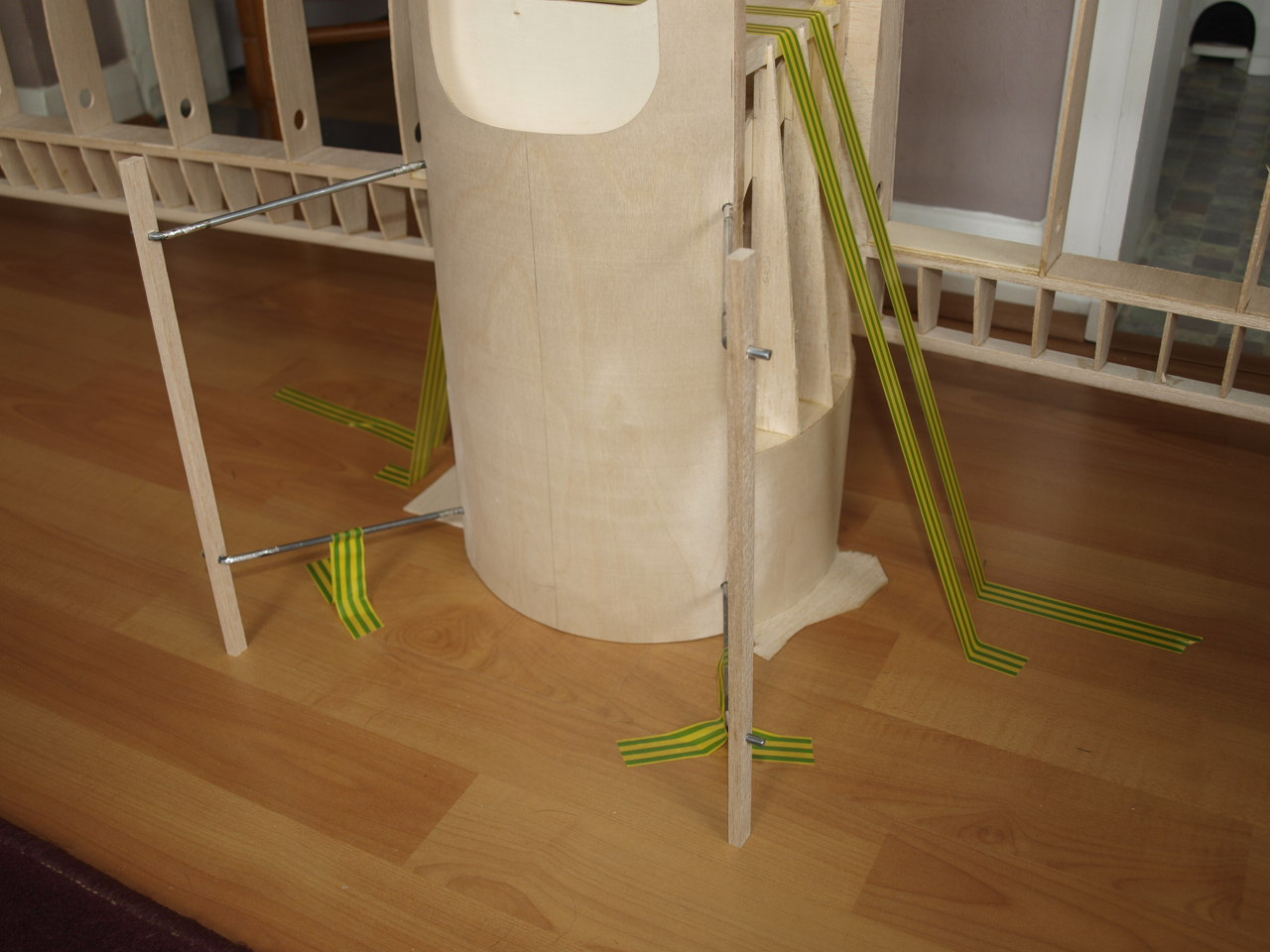
Once this had been done the fuselage and the struts where married up and firmly secured to the level surface ready for tack soldering see picture below
Once all was secure the cross wires where
located one at a time and tacked into position.
The second picture shows the tacked up cabane strut removed from the fuselage
ready to be bound with fuse wire. This method of building the structure is so
much easier than trying to bind with the wires whilst situated on the model.
 |
 |
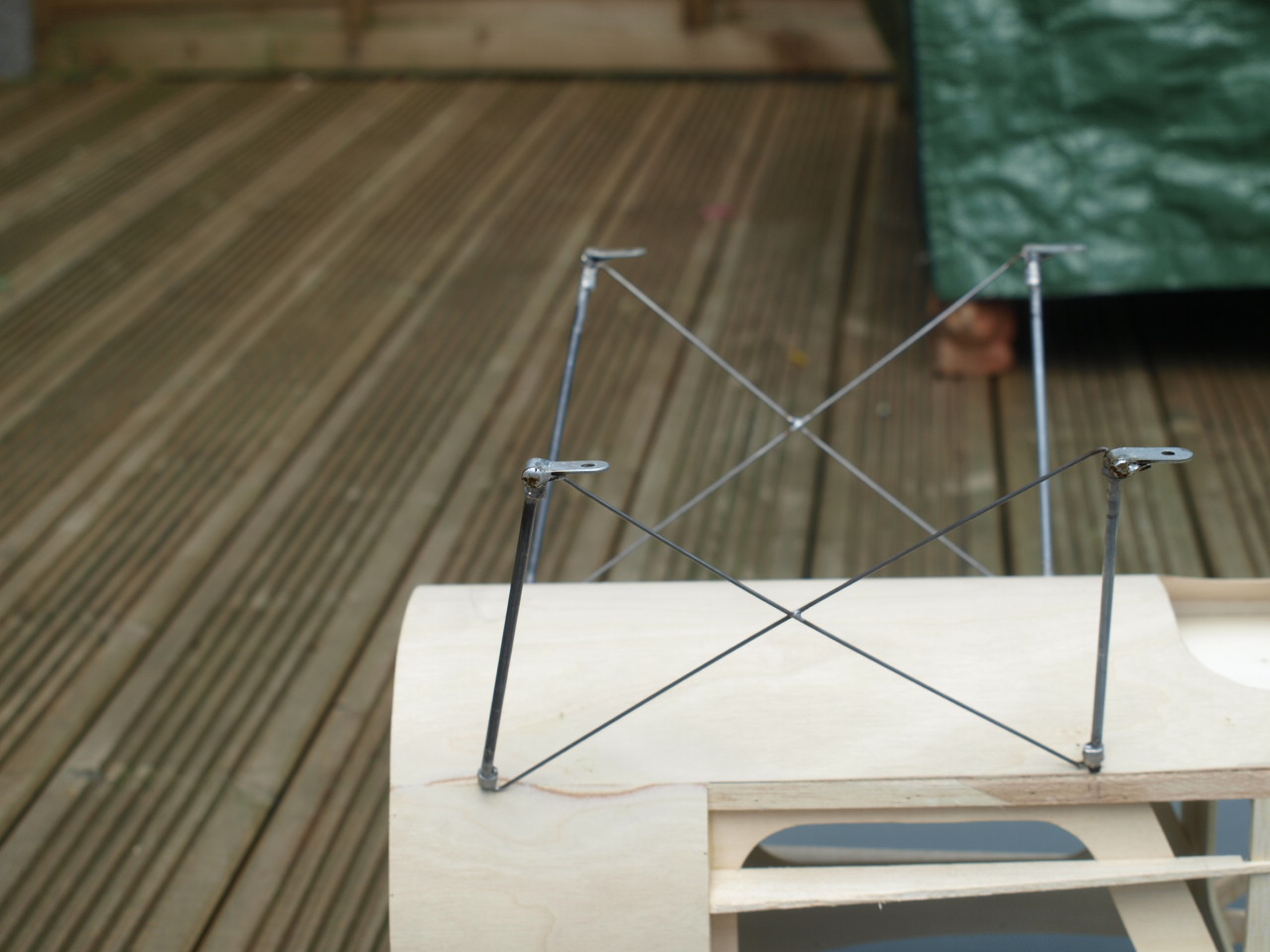
Once all bound up the structure was re located back onto the fuselage and checked again for square. Once happy the bindings were all soldered up giving a nice strong joint (pic 1 below)
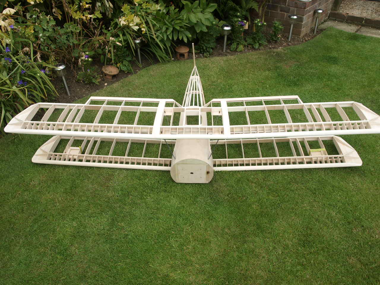
The Second picture shows both struts finished and sitting in their correct positions.
 |
 |
The next picture shows the wing mounting
brackets soldered into place. The brackets are place over the cabane struts and
then crimped with pliers to form a tight fit. The fuselage is turned upside-down
so that the brackets are resting on a level surface. Once I was happy that all
where sitting square they are soldered into position.
The upper wing is then
placed upside down and chocked up. The fuselage again upside down placed on to
the ply plates that receive the cabane structure. The position of the wing has
to be lined up so that it is square with the fuselage using the same method as
that when we lined up he bottom wing for square ness. Once square the holes in
the mounting brackets are marked on the ply plates and then drilled to 3/16 dia.
(picture 2)
 |
 |
Once drilled out a captive nut is pushed through the hole and pulled into position The wing can now be bolted into position. The bottom wing is placed onto the fuselage and the two eyed up to ensure everything is square (Pictures below)
 |
 |
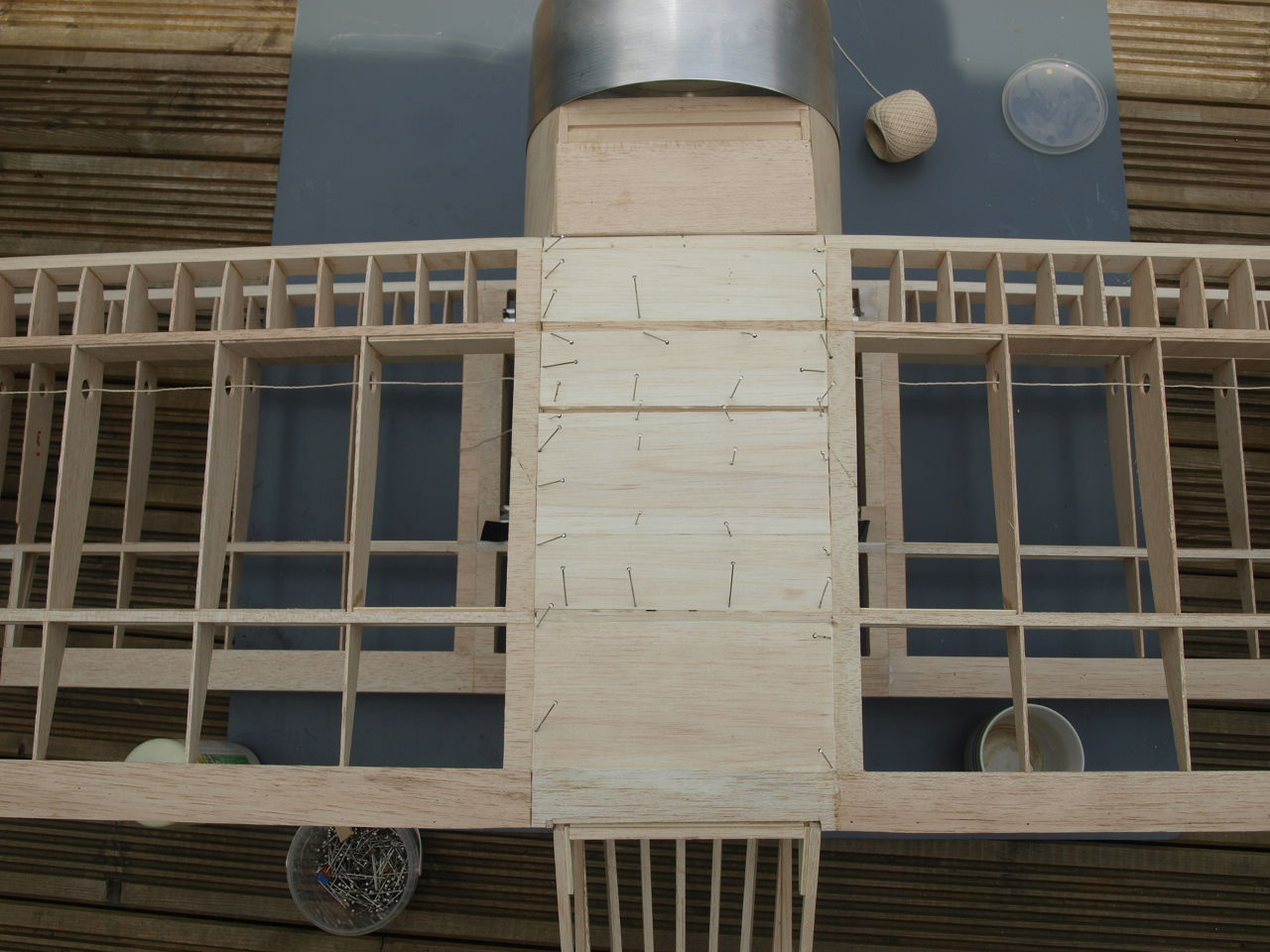
With the wing in place I decided it was as
good a time as any to finish of the final construction of the centre section.
All that is left here to do is glue in the undercarriage mount and the balsa
sheeting.
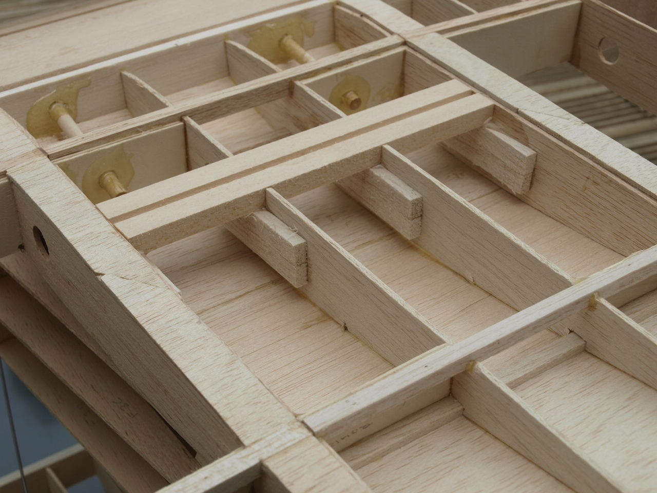
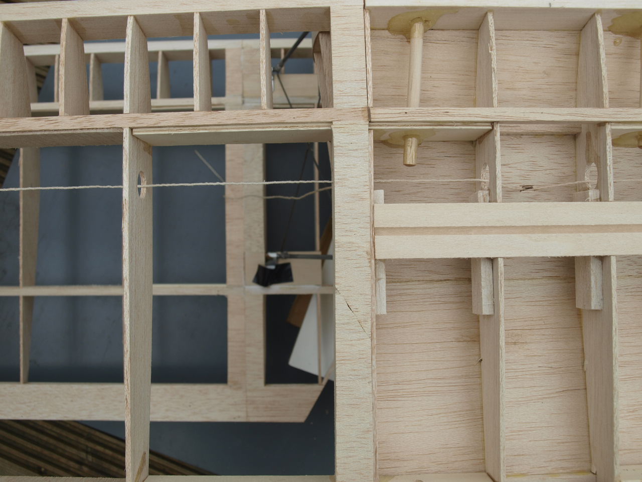
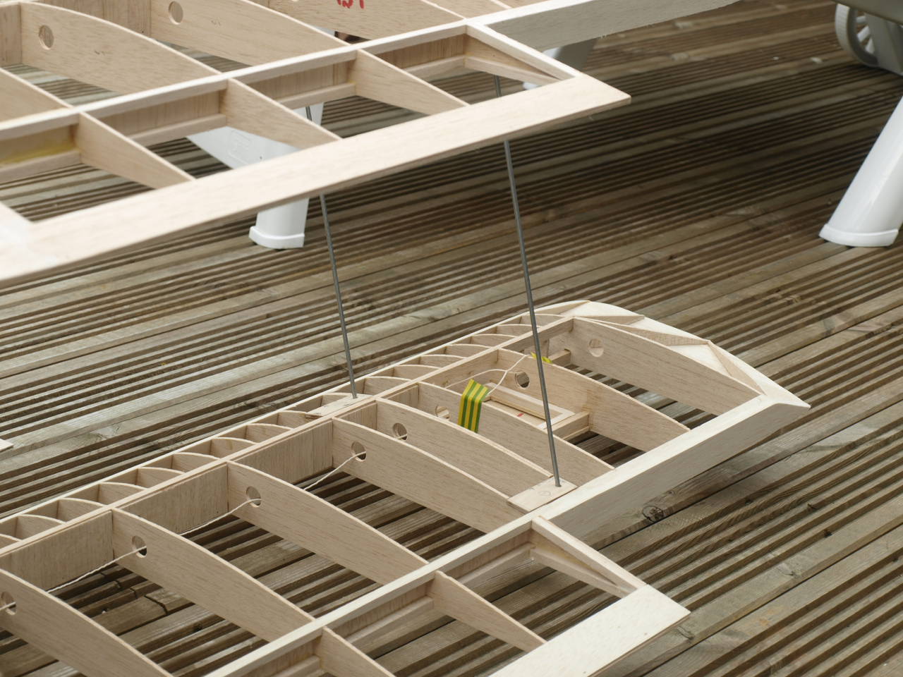
In the second picture below, you will see that I have run string
through the ribs out to the servo hatches and also made a small opening in the
top sheeting and threaded the string through this.
The String will be used when
I install the servo leads as once the bottom sheeting of the wing is
placed in position, it will be very difficult to locate the holes in the ribs. You can also
see in the first picture below the undercarriage block in place. The balsa
blocks glued to the ribs and undercarriage mount are not as per the plan and I
have added then to add additional strength to the structure.
 |
 |
The next picture shows the balsa sheeting in place.
Picture 2 shows the outer strut mounting ply plate in place, which has been drilled to 5/32 ready to receive the metal rods that help make up the structure. The process is carried out for both top and bottom wing
The hole locations where taken and transferred from the wing plans using tracing paper .
 |
 |
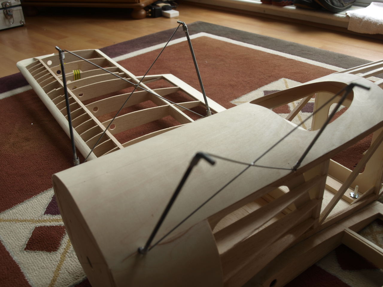
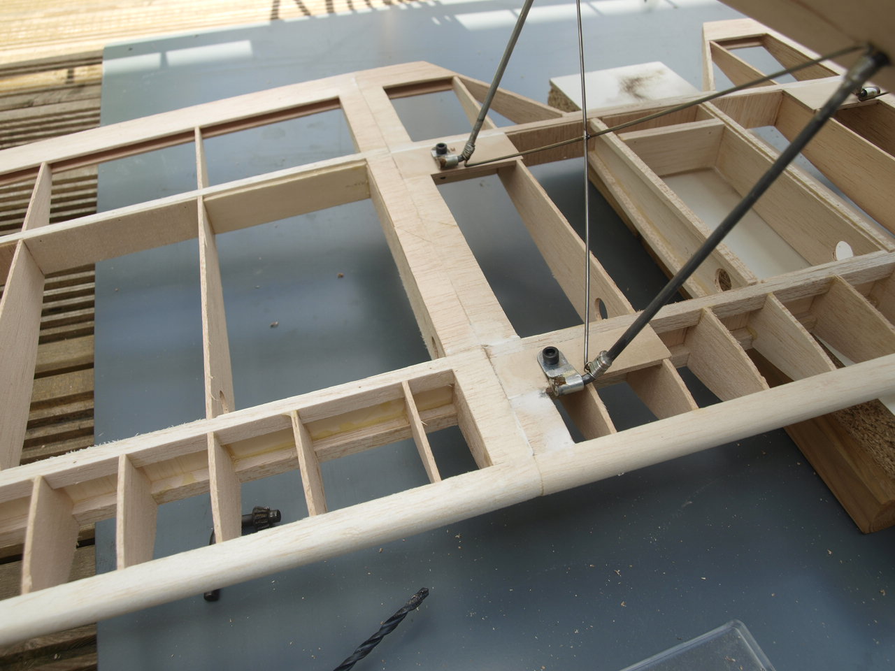
The two pictures below show the steel wires in position for illustration only at this point. Their final setup will be covered next. See Struts and Linkages page
 |
 |
Stabiliser Construction
Rudder construction
Wing Construction
Aileron installation
Struts & Control Linkages
Engine installation
Final Construction
Sopwith Page
Home page