STRUTS AND CONTROL LINKAGES
I can't put it off any longer, so have started the construction of the struts. I have been dreading starting these, as the instruction manual when reading, has really confused me. Anyway here we go.
The first thing that is needed to be done is to bolt on
the bottom wing to the fuselage and the top wing to the cabane struts. Once this
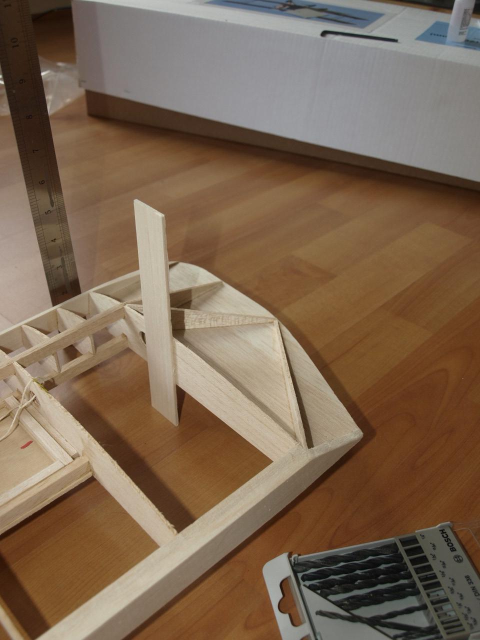
is complete you need to place the structure on a level surface. Once in place
with a ruler measure at each wingtip of the lower wing from the ground to the
top of the wing main spar, ensuring that you have an equal measurement both ends
. Once this is achieved, tack glue scrap balsa sheets in place ensuring
that the structure can't tilt or move. (see first pic below). Once you have done
this measure from the ground up to the top main spar of the top wing and make
sure as you did with the bottom that the measurements are equal both ends. If
not then you will need to loosen the top wing from the cabane struts and
shim up the wing until you have achieved an equal measurement both ends. Luckily
for me I did not have to do the later.
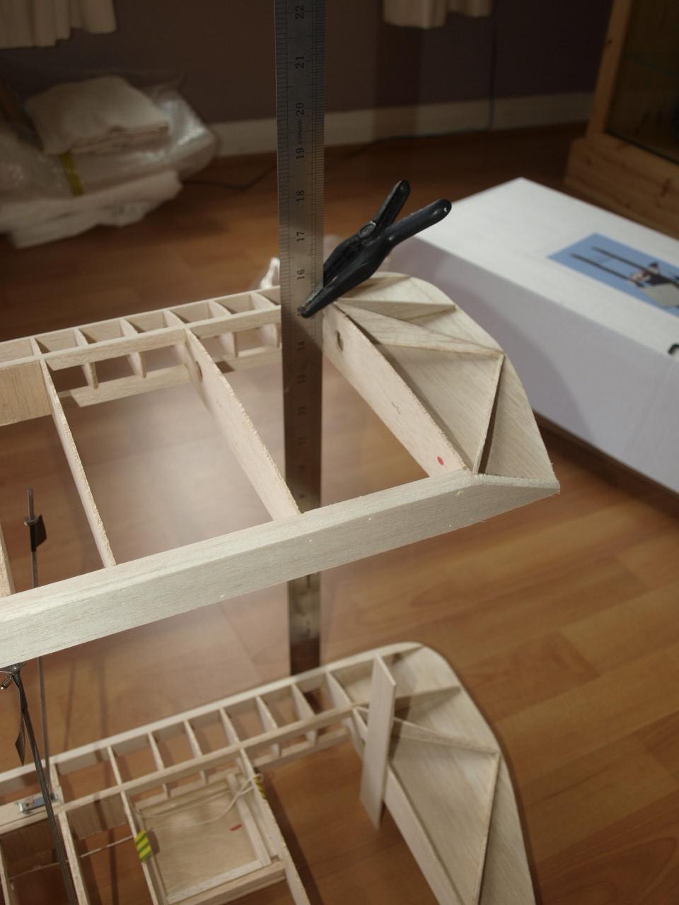
To ensure that the top wing did not move
whilst working on the inter plane struts I clamped two long rules into
place at both ends of the wing. (See pic 2 below)
|
|
|
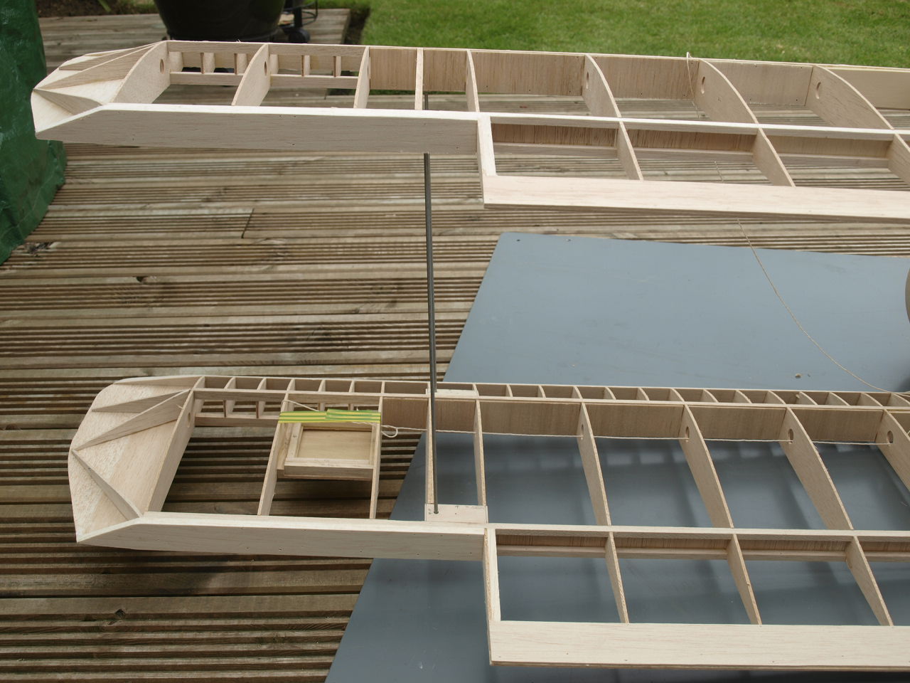
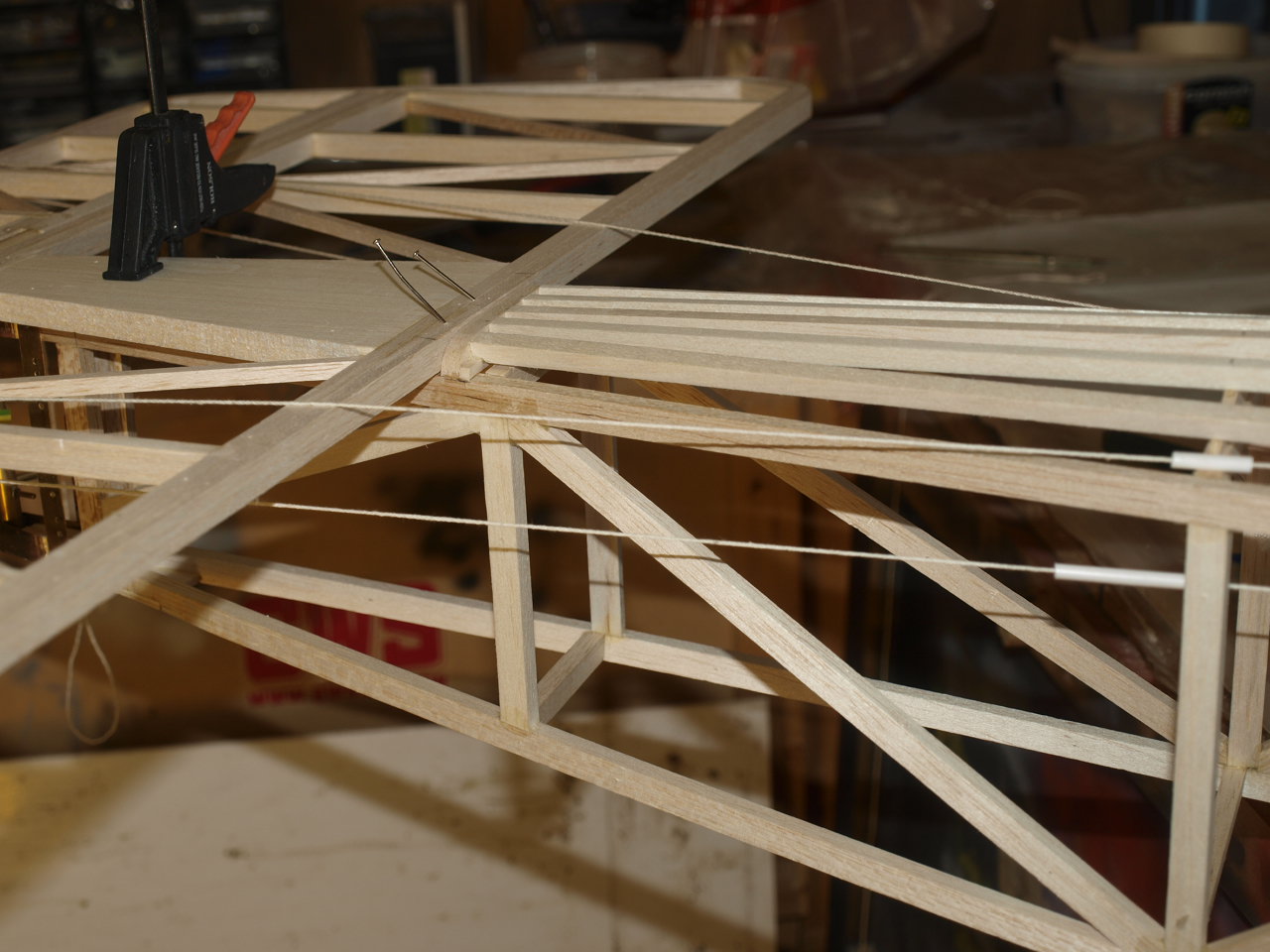
The next two pictures below show the inter plane wires in position after holes had been drilled as shown on plan. This was done prior to the above as I wanted to figure out how this was all going to work.
 |
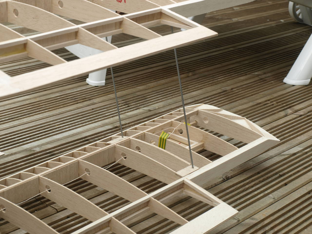 |
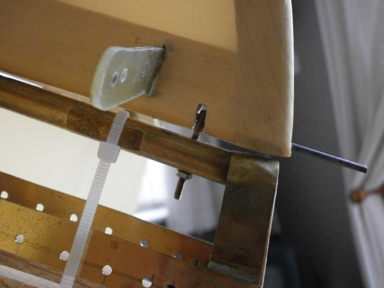
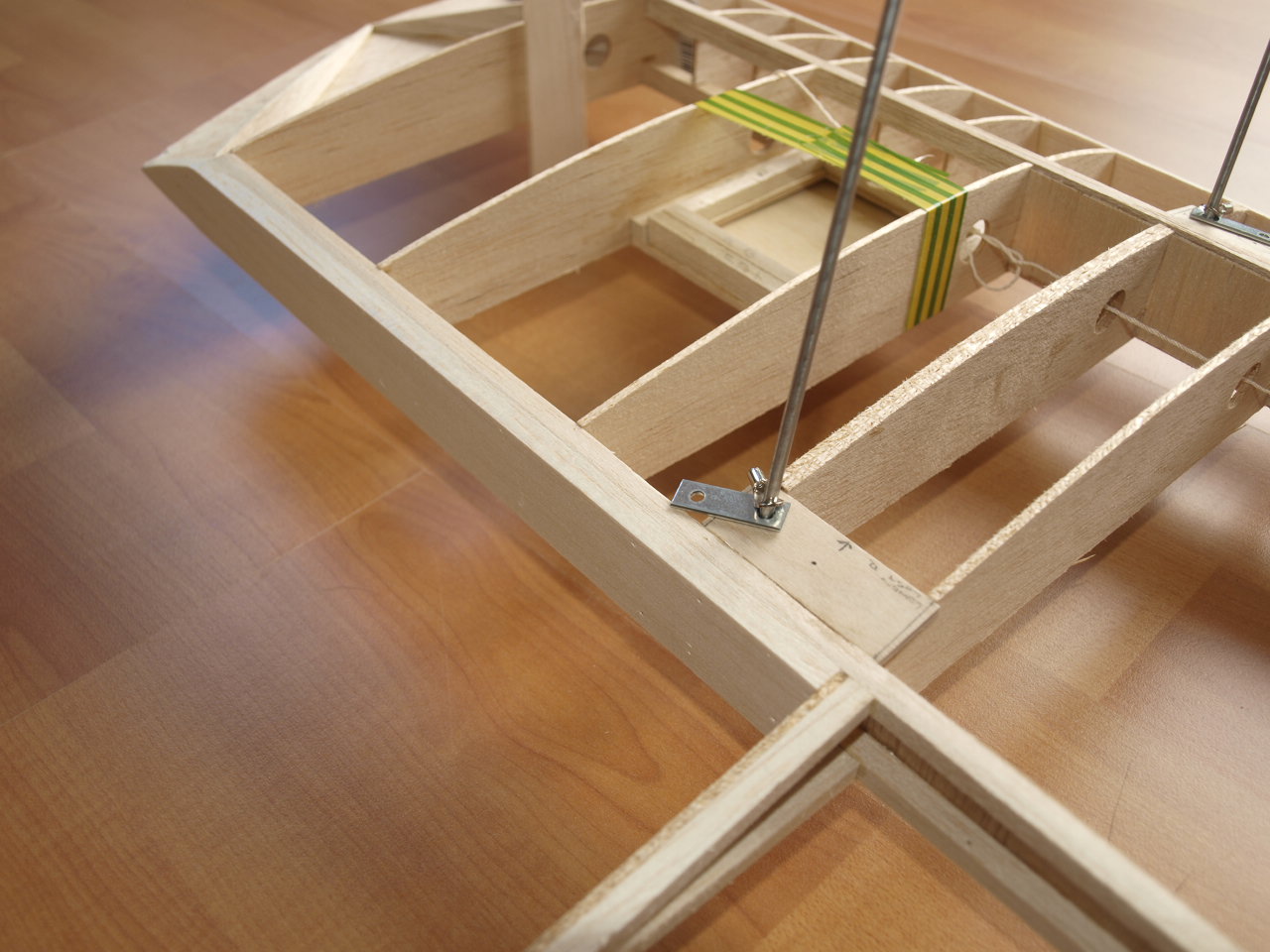
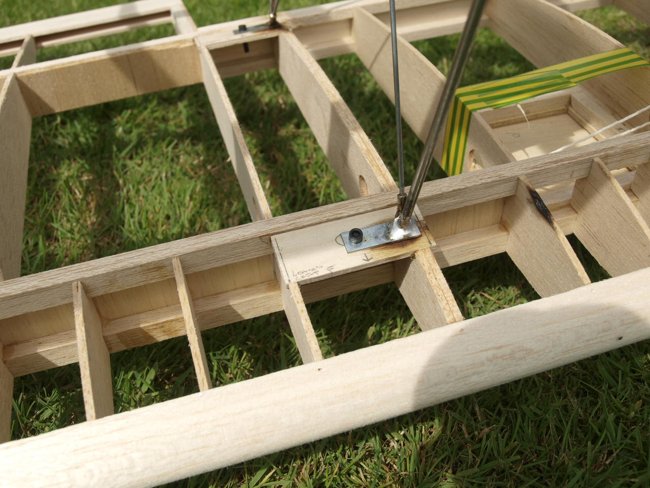
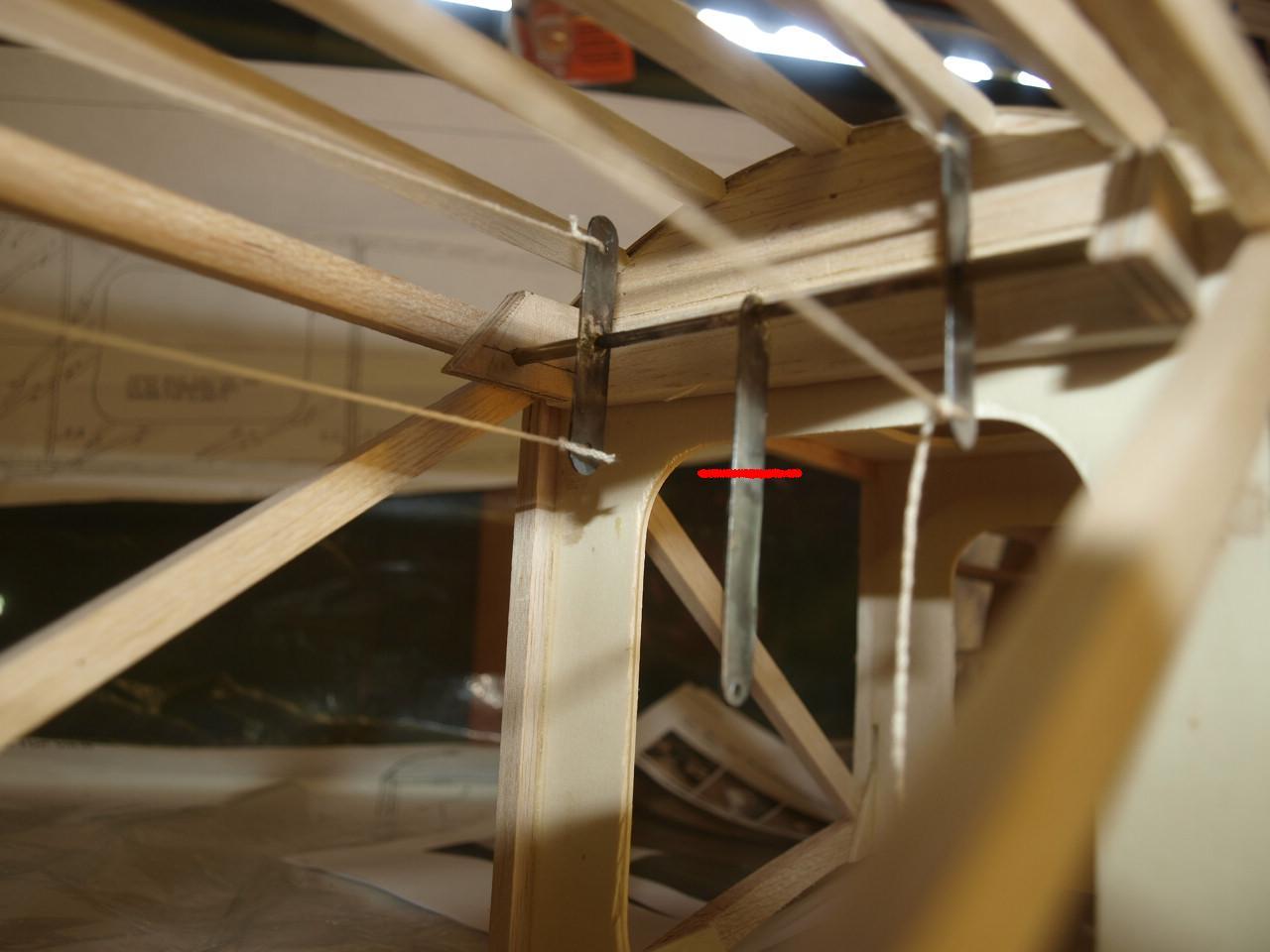
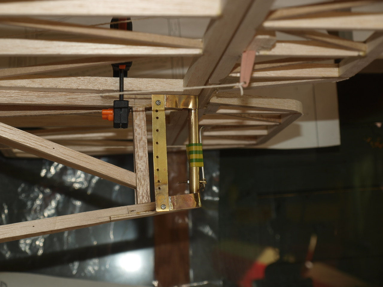
With the plane all squared up now as explained above, the piano wire rods have a small metal fitting placed on then, one for the top and one for the bottom wings, with a small solder lug above them. (see pics below). Note the other hole. This holes position is marked once squared up and the ply plate drilled out to accept a captive nut that will accommodate the bolt that secures the structure once complete.
 |
 |
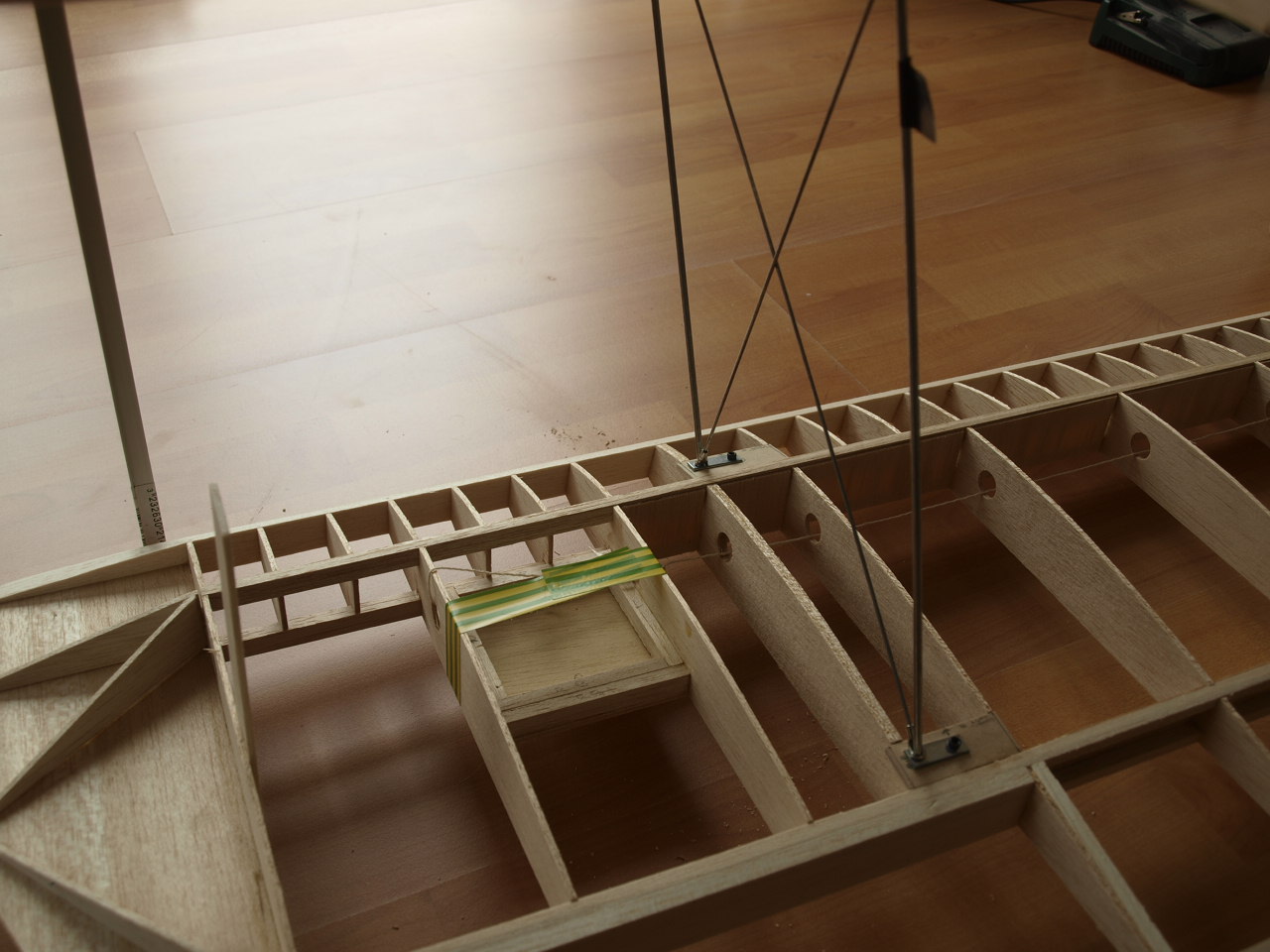
The next bit is the tricky bit and takes a considerable time to measure up and cut. These are the cross wire pieces. It is critical that they are measured and cut accurately, as these will be what keep the struts square and true once they are removed from the wings. These wires locate in the solder lugs and need to be cut to size which is very tricky as you do not want cut them to short, but trying to measure their exact length took a lot of patients, as the lugs keep moving out of alignment. I should have got someone to help me here, as two pairs of hands would have been better than one.
Anyway after about two hours of cursing and swearing I finally got there.
Now these all need to be soldered up another job that I do not enjoy.
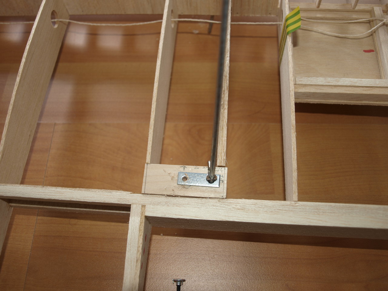
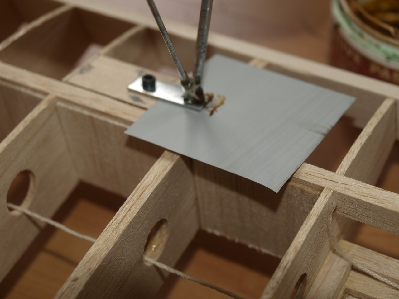
The first pic below shows the structure ready to be
soldered and the second picture shows a little gig I made up to slide under the
metal fitting to reduce the scorching of the ply plate when soldering.
I
soldered the bottom wing first checking to ensure nothing had come out of
alignment before moving on to the next joint, This process was carried out until
all eight joints had been completed.
 |
 |
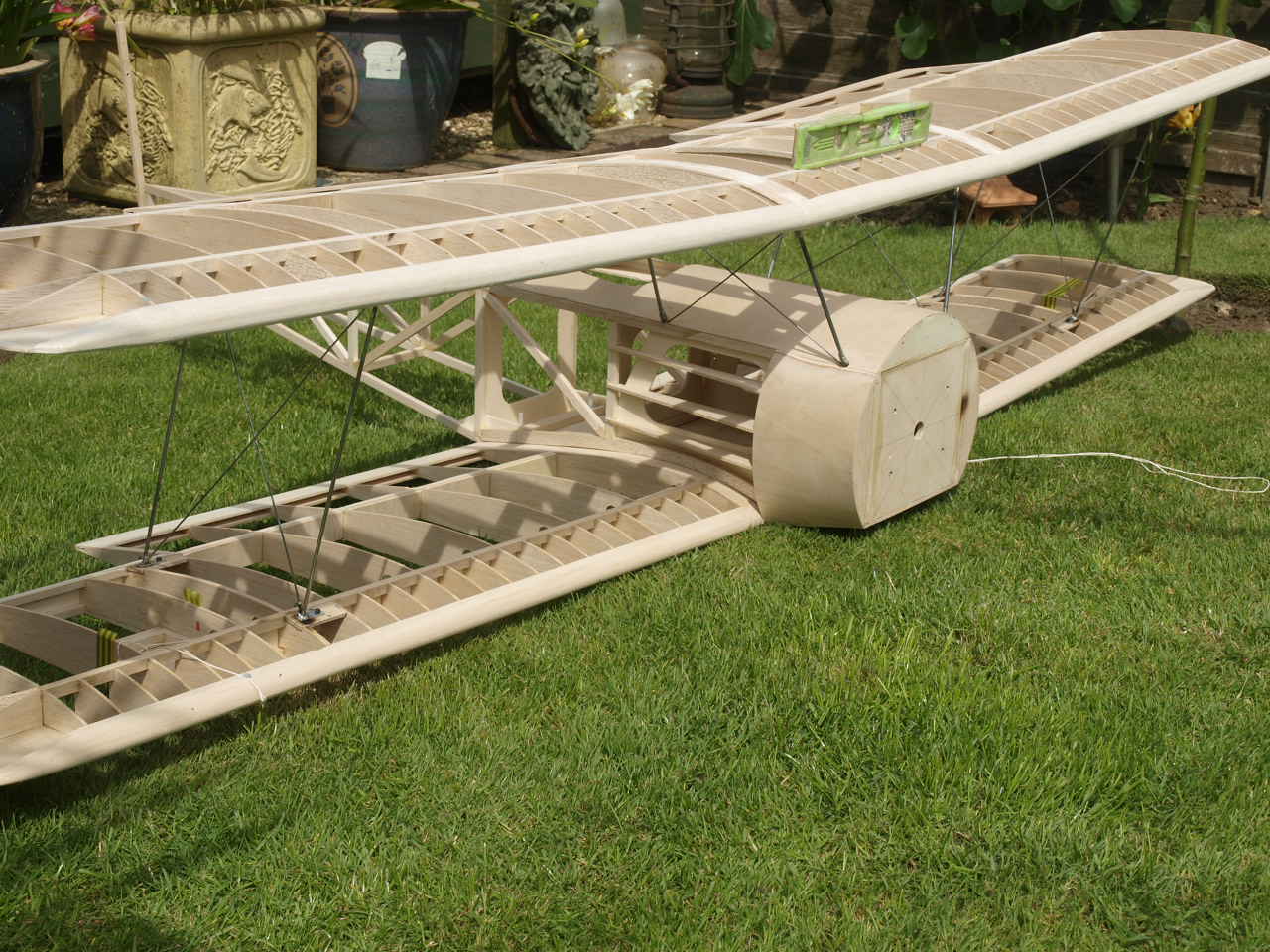
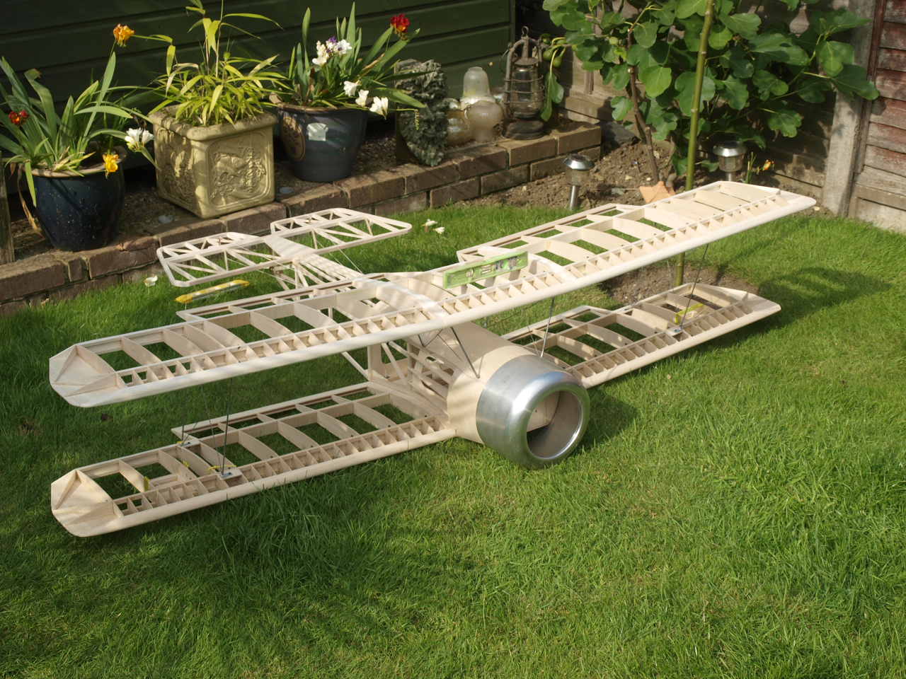
The next couple of picture show the whole assembly completed. I must say that this has been the less enjoyable part of constructing the model so far and caused the most headaches.
 |
 |
As mentioned before I'm trying to achieve a reasonable
scale look to this model and my research has thrown up a feature that is quite
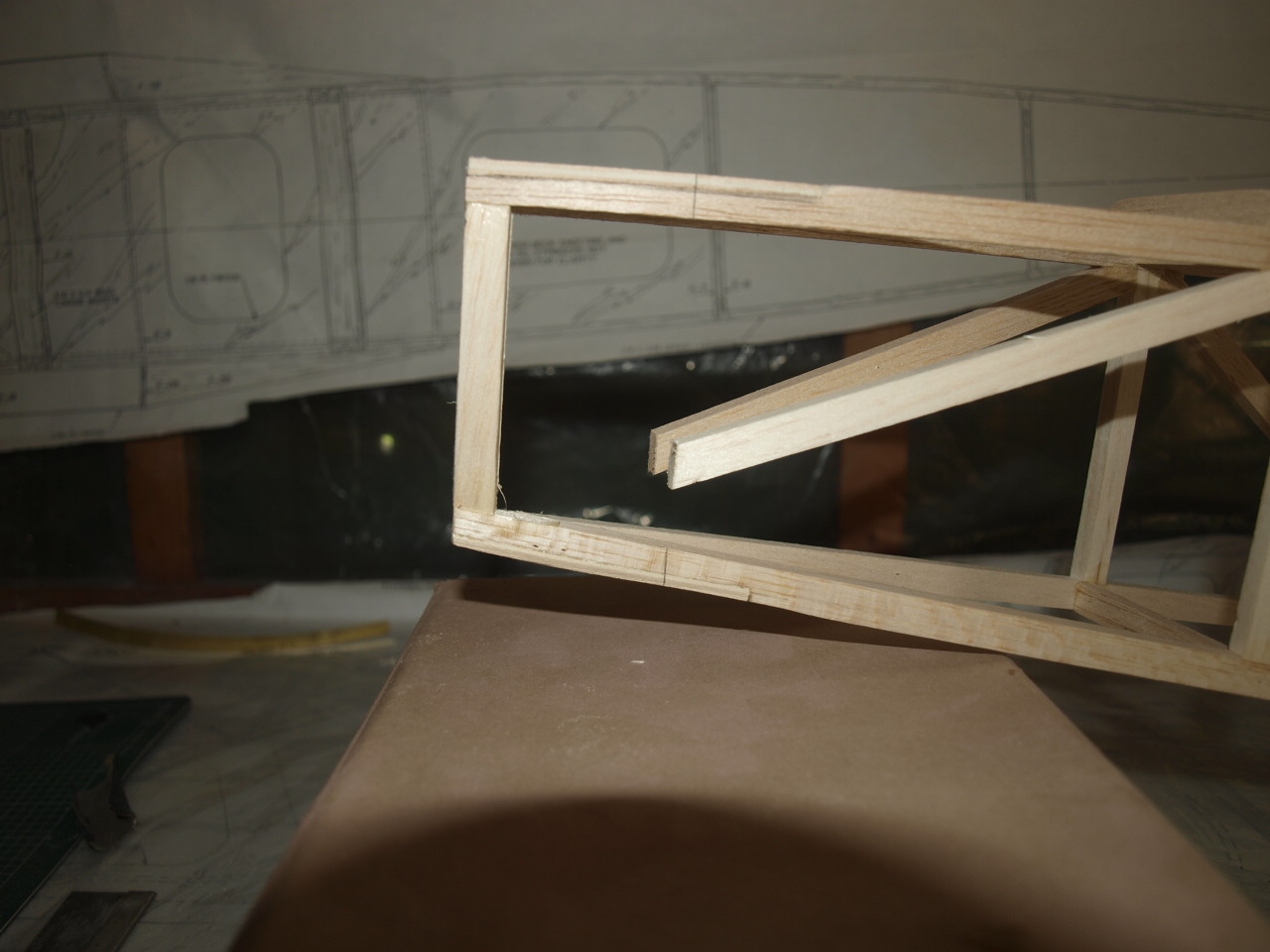
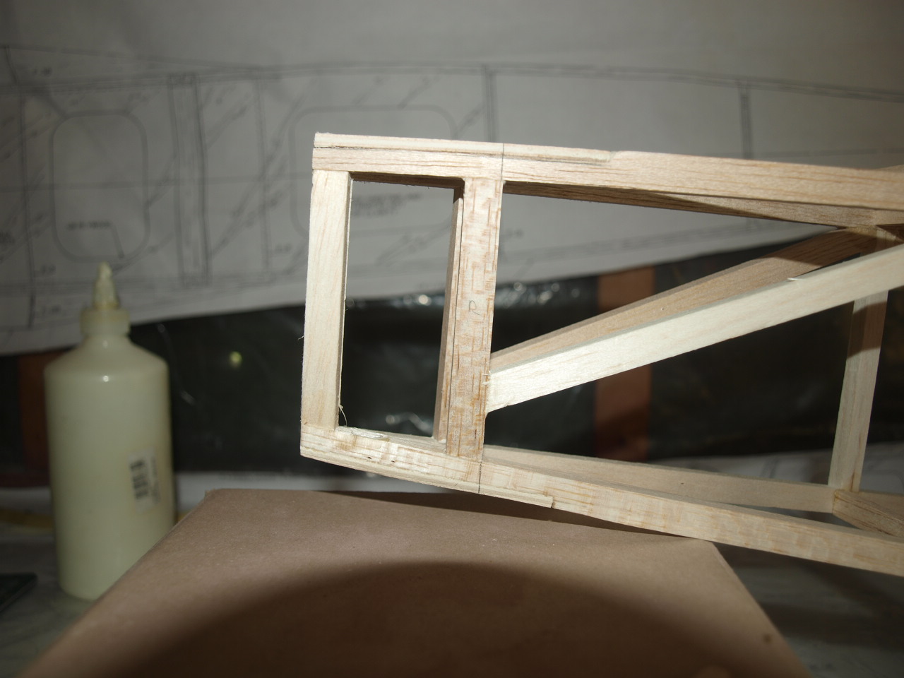
pronounced on some pups. This is the open ended tail end of the fuselage which
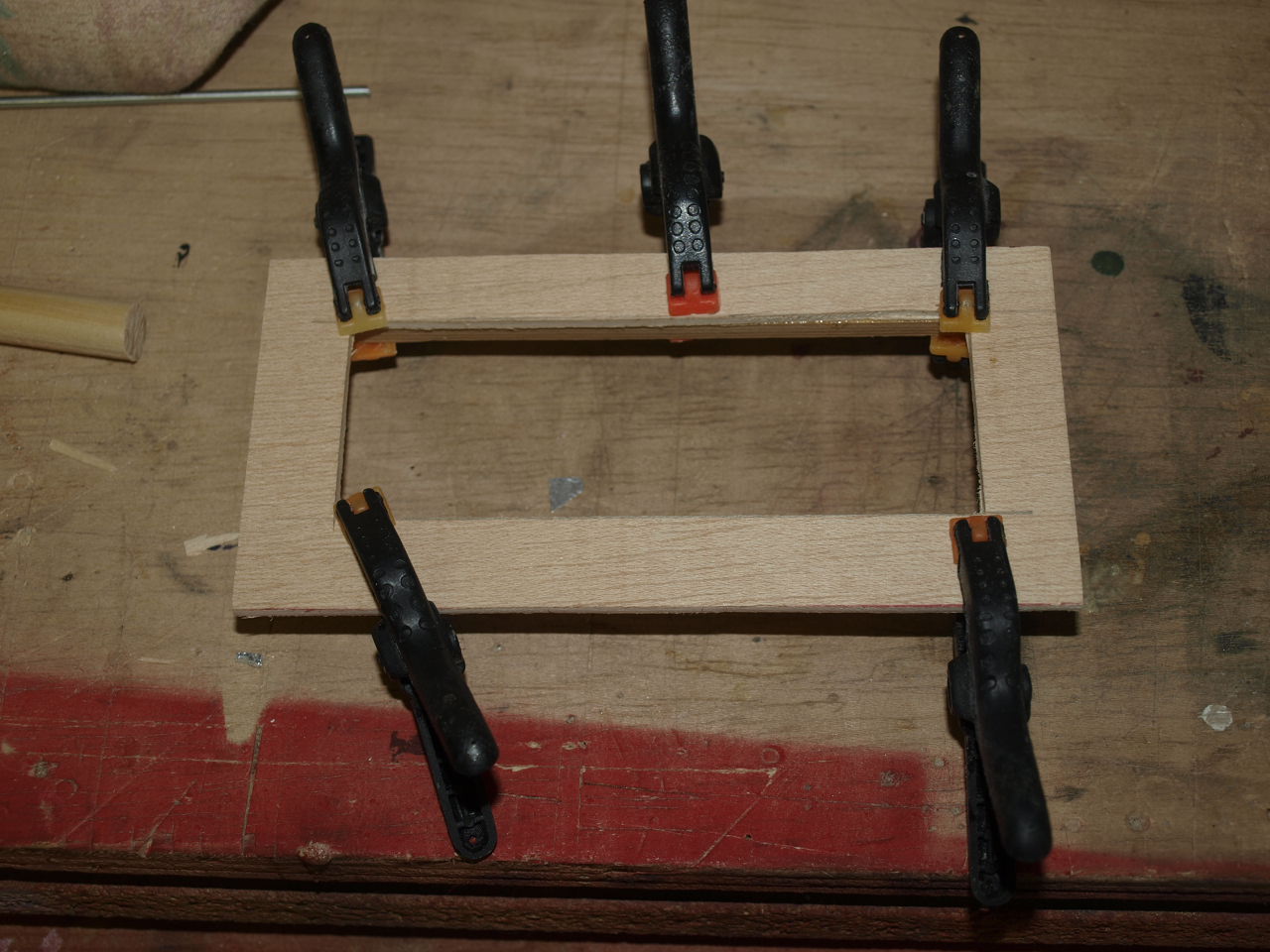
is made up of a metal fitment. To achieve this I needed to do was cut
back the cross braces just past where the new fitment would be placed. (Pic 1
below)
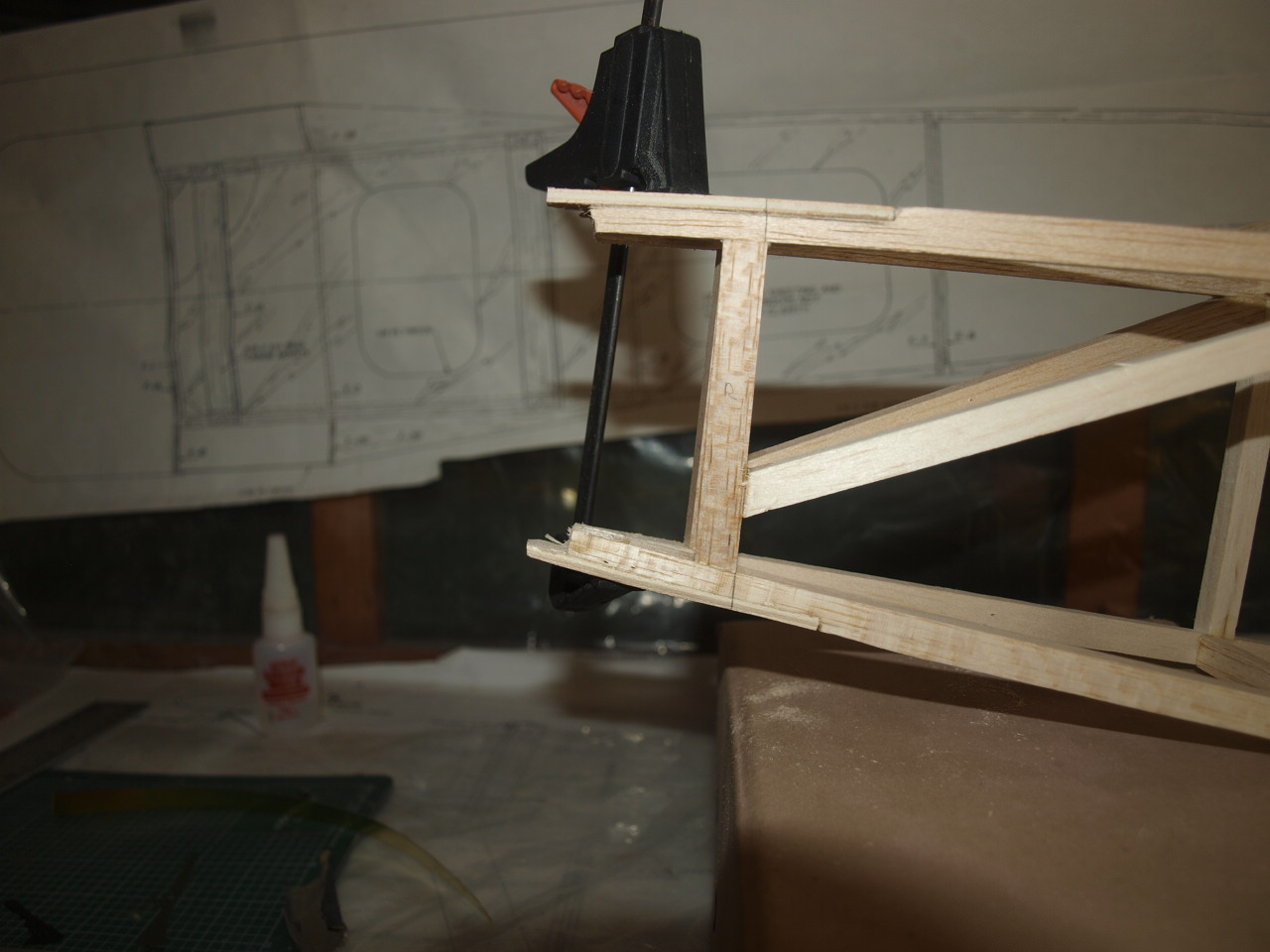
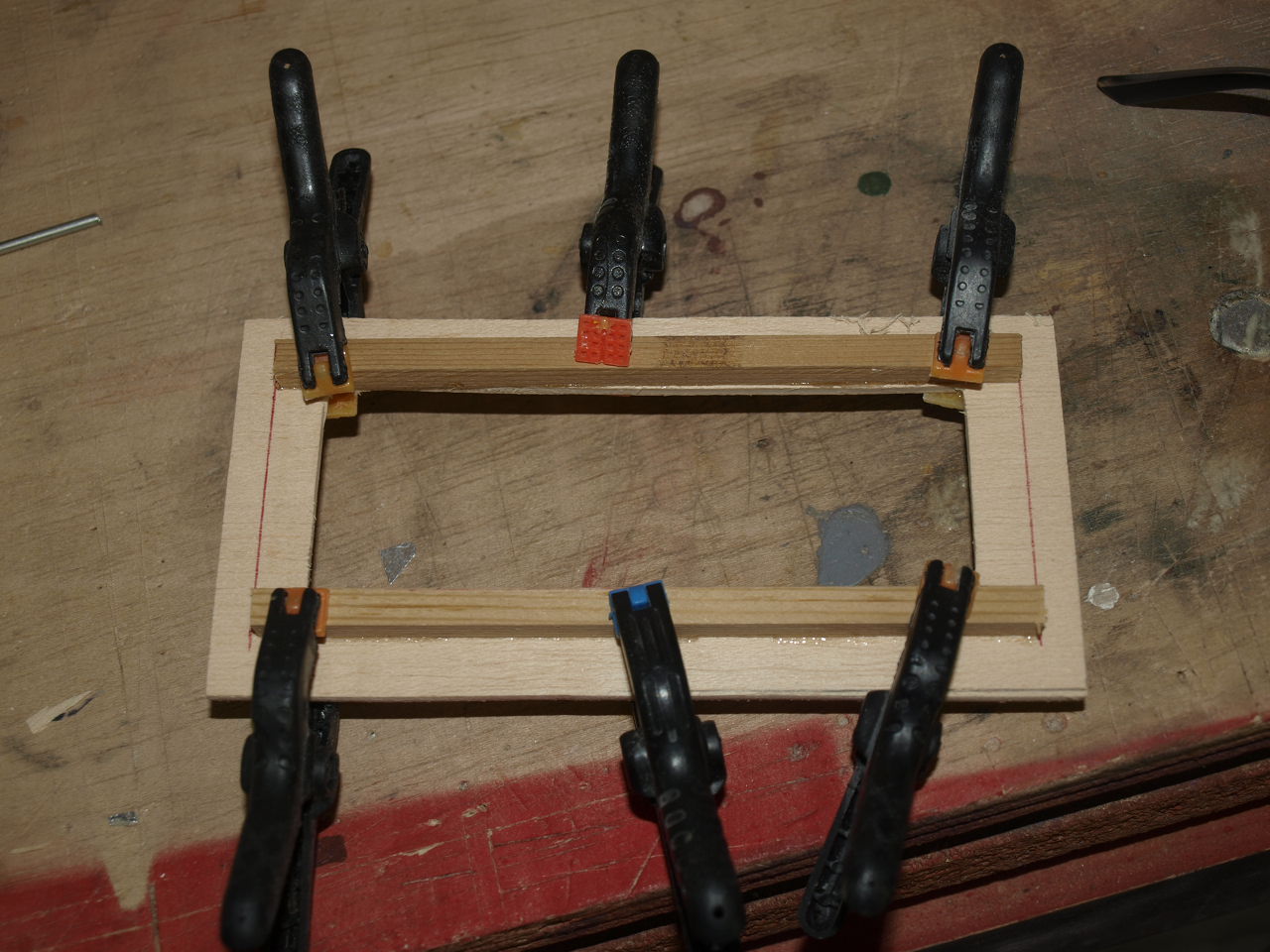
Next a new vertical brace was added and the cross brace glued to this ( Pic 2 below )
 |
 |
Once the above was cured the original fuselage end was carefully cut out but leaving the triangular plates in place as these will be required to accept the brass tube, (see pictures below) note the clamps keeping every thing in place at this stage.
 |
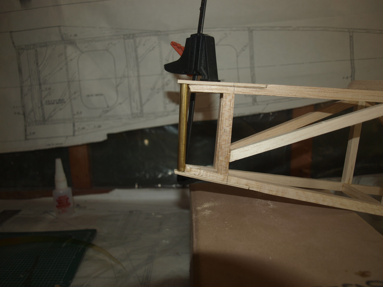 |
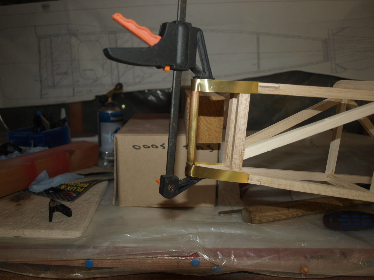
With the brass tube cut to size and clamped into position, strips of pre-cut 1/64 brass sheet are placed and moulded around both the tube and the fuselage frame (Pic 1 below). These are then removed and soldered to each other, refitted to ensure everything square and then removed again so that the vertical brass strips can be soldered into place. (Pic 2 below)
 |
 |
With this completed and test fitted again the holes where drilled. These will be used to accommodate the stitching that secures the covering material as per the full size aircraft. In the second picture below you can see the rudder hinge mechanism that will hold the bottom portion of the rudder in place. A hole is drilled through the brass tube now making up the rear end of the fuselage and into this I used a closed loop fitting secured with a nut. The eye of the closed loop now protrudes out of the back of the fuselage. This will locate in to a slot cut into the rudder and then in turn will be held in place by a length of piano wire inserted through a brass tube previously installed into the end of the rudder. This holds the lower portion of the rudder in place whilst the top half is hinged in the conventional manner. see pictures below
 |
 |
|
|
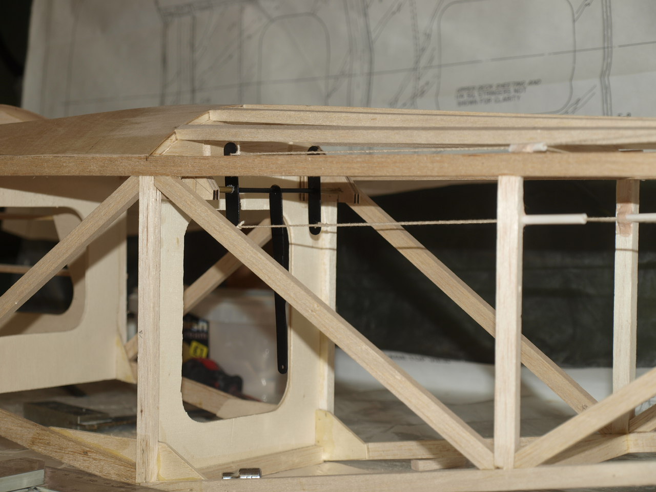
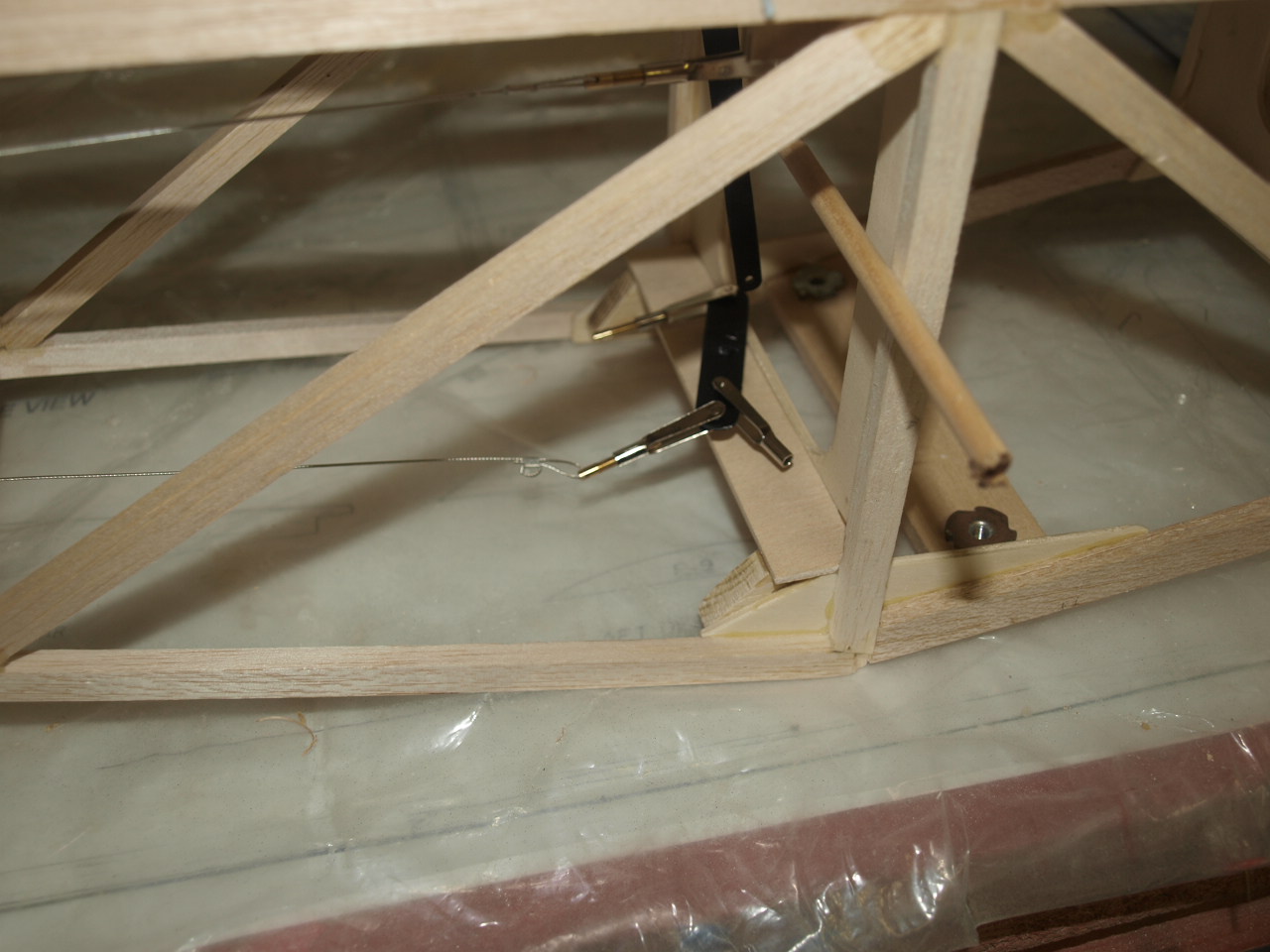
Moving onto the elevator linkages again these have been made up from scratch. It took quite a bit of working out where to position these as I wanted the wires running from these to exit the fuselage as per those on the full size. After a lot of trial and error the final location seen in Pic 2 below was decided upon.
This linkage was made up of piano wire 1/16
steel plate, brass tube and ply wood blocks.
First the piano wire is cut to length. Then the steel horns are measured up and
cut to size. It is important to ensure that they are identical and that the
holes drilled either end (these will accept the linkage wires ) are identical
for both horns. Next the centre horn is made up to size again making sure
everything is square.
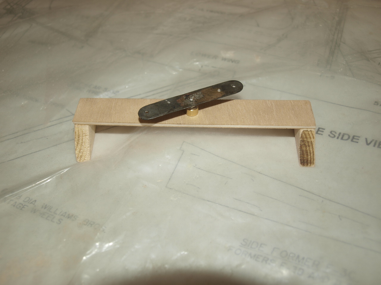
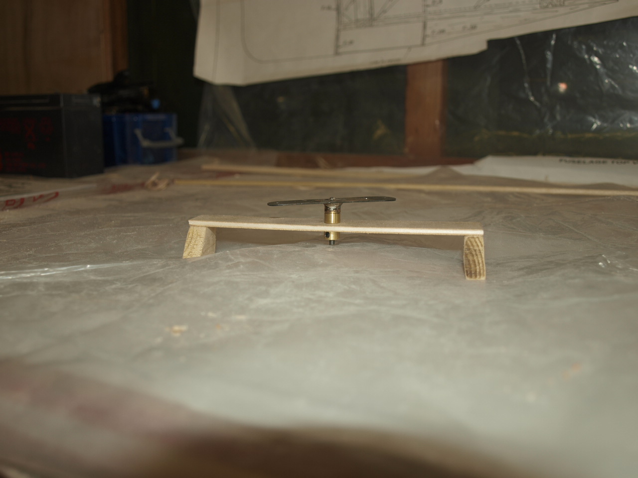
Once made up these are placed onto the piano wire (see pic below) and brazed into place, again ensuring that everything remains square. Once this is complete the brass tube is cut to length and slid over the piano wire, it should butt up against the horns with a fraction over hanging the piano wire ends. This brass tube in turn, then sits into the ply blocks which are drilled to accept them but not all the way through. Once coupled together the assembly is mounted into position as seen in pic 2 below.
The First picture below shows the central linkage arm somewhat extended This has since been cut down in length ( see pic 2) as I could not get the required elevator movement suggested in setting up the throws (you live and learn)
 |
 |
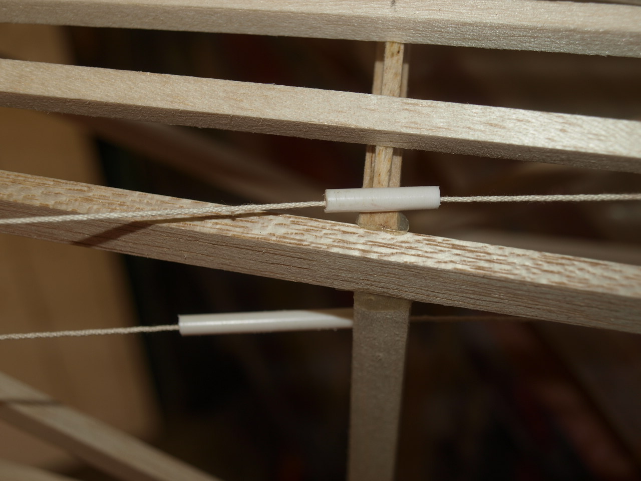
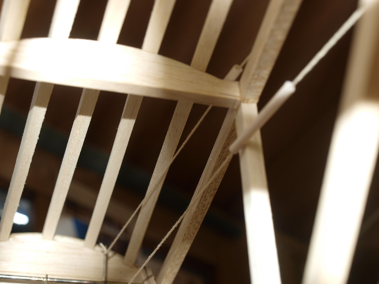
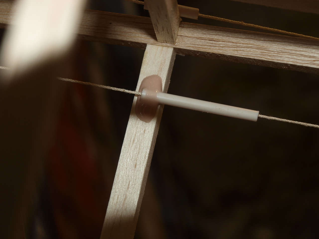
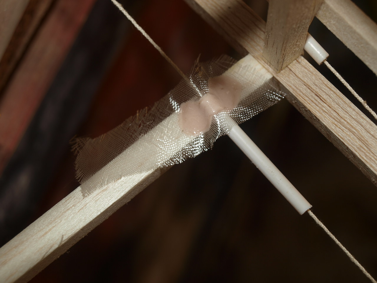
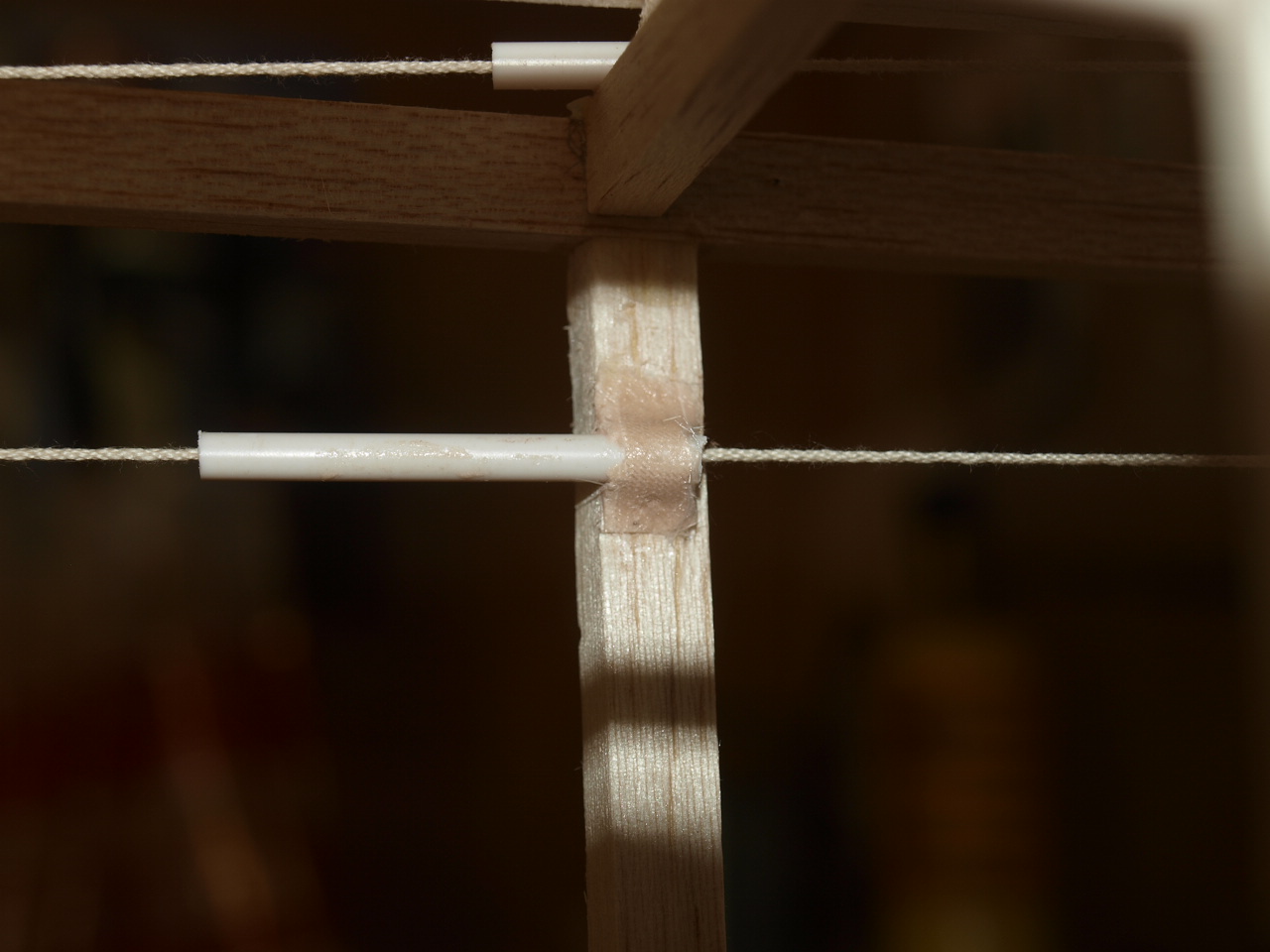
Where the wires exit the fuselage as seen in the pictures below I have used plastic wire guides that have been glass fibered into position. See following set of pictures below.
Note cotton cord running from linkage to elevators used to set up the correct angle of exit tubes and cable run to elevators
 |
 |
 |
 |
 |
 |
 |
 |
With the elevator linkages sorted out I then
moved onto the rudder linkage. Again 1/16 steel plate was used to make up he
horn. This was made up as per the elevator horns and a length of piano wire
brazed on to this.
This once cooled was turned upside down with the piano wire sticking up. Onto
this a brass wheel collet is slid over and this is then soldered into position
onto the horn. Next another collet is placed over the wire but left to run free.
A length of ply is then cut to size and a hole drilled in the centre. The horn
linkage is then turned the right way and the piano wire pushed through the hole.
The assembly is now turned again and a further collet placed and secured into
position resulting in a free moving rudder horn linkage. See pictures below.
 |
 |
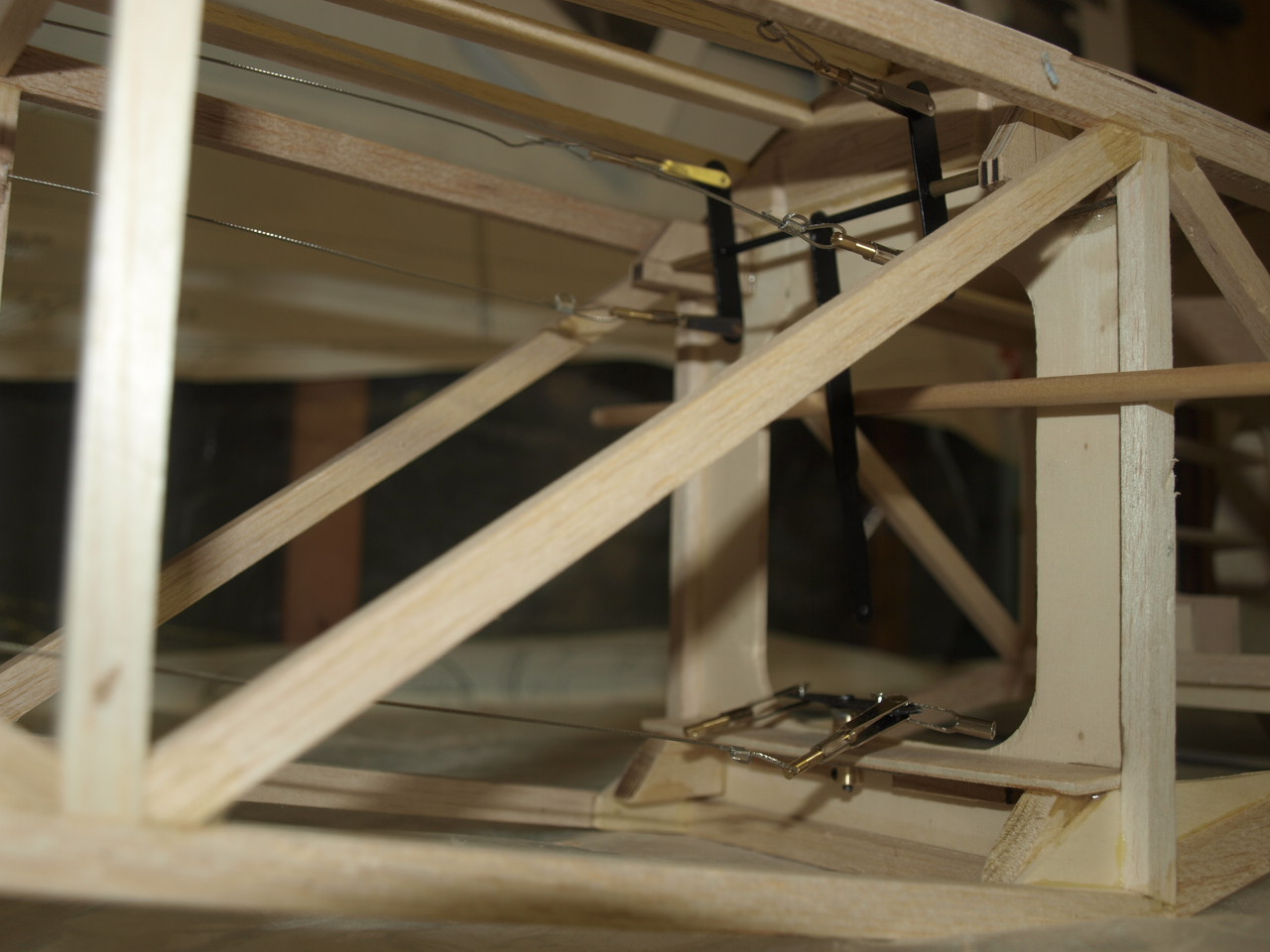
Pictures below showing rudder assembly in position with linkage wires installed.
 |
 |
Just had to put her together again.
 |
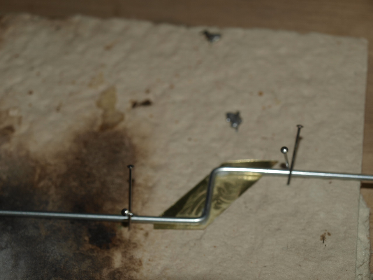 |
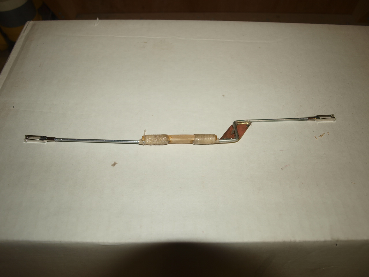
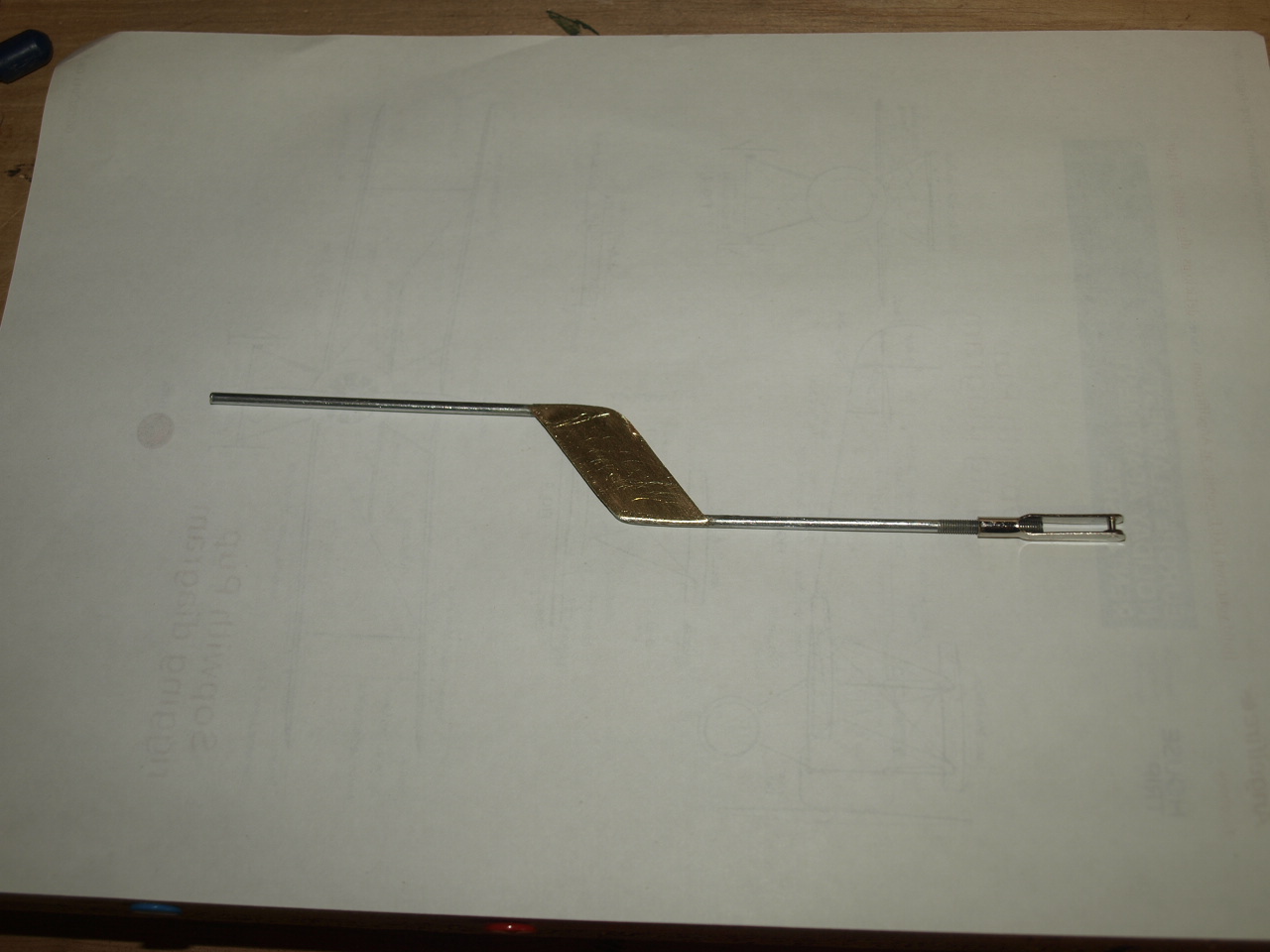
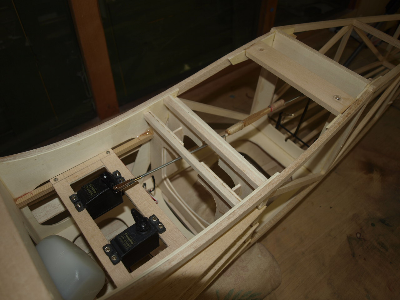
With the linkages in place the next job is to establish the best run for the push rods that will link closed loop to the servos. The added complication here is that I'm using a full scale pilot and therefore need to ensure the pushrods do not come into contact with his feet. This means that I need to keep them as close to the bottom of the fuselage as possible. The elevator pushrod is not problem but the rudder was a little more of a problem. To get over this I decided to step the rod which worked a treat. The only problem with this is that with a model of this size the pressures applied on the rudder in flight could cause the wire to flex under the strain. To over come this I have soldered a small brass plate into position across the step that will prevent any flex /movement occurring. See pics above and below.
 |
 |
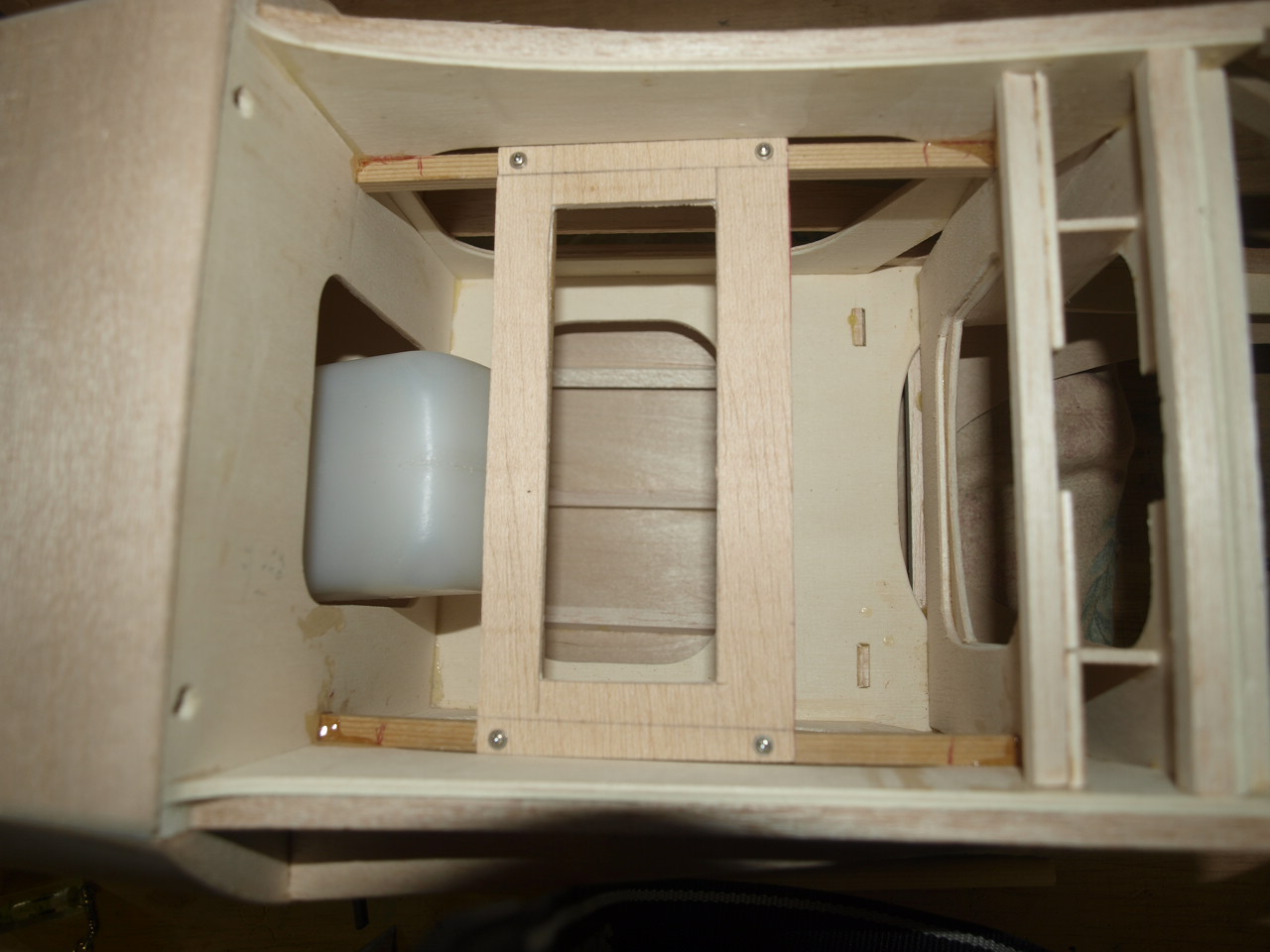
The servo tray has been installed as far forward as possible which can be seen below and is made up of Spruce rails epoxied either side of the fuselage and then a ply tray installed with an aperture large enough to accept the rudder and elevator servos, this has been reinforced with spruce strips that will accept the servo securing screws. See pictures below
 |
 |
Once all cured the tray is screwed to the spruce rails. By screwing the tray into position it can be easily removed to give unrestricted access to the fuel tank and any of the radio fittings housed directly below it.
If you click the link below this will take you to a short video showing some of the process to get to the stage shown in pic 2 below
 |
 |
pushrod and closed loop system
Stabiliser Construction
Rudder construction
Wing Construction
Aileron installation
Fuselage page
Engine installation
Final Construction
Sopwith Page
Home page