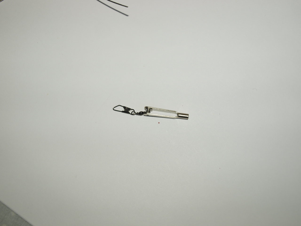
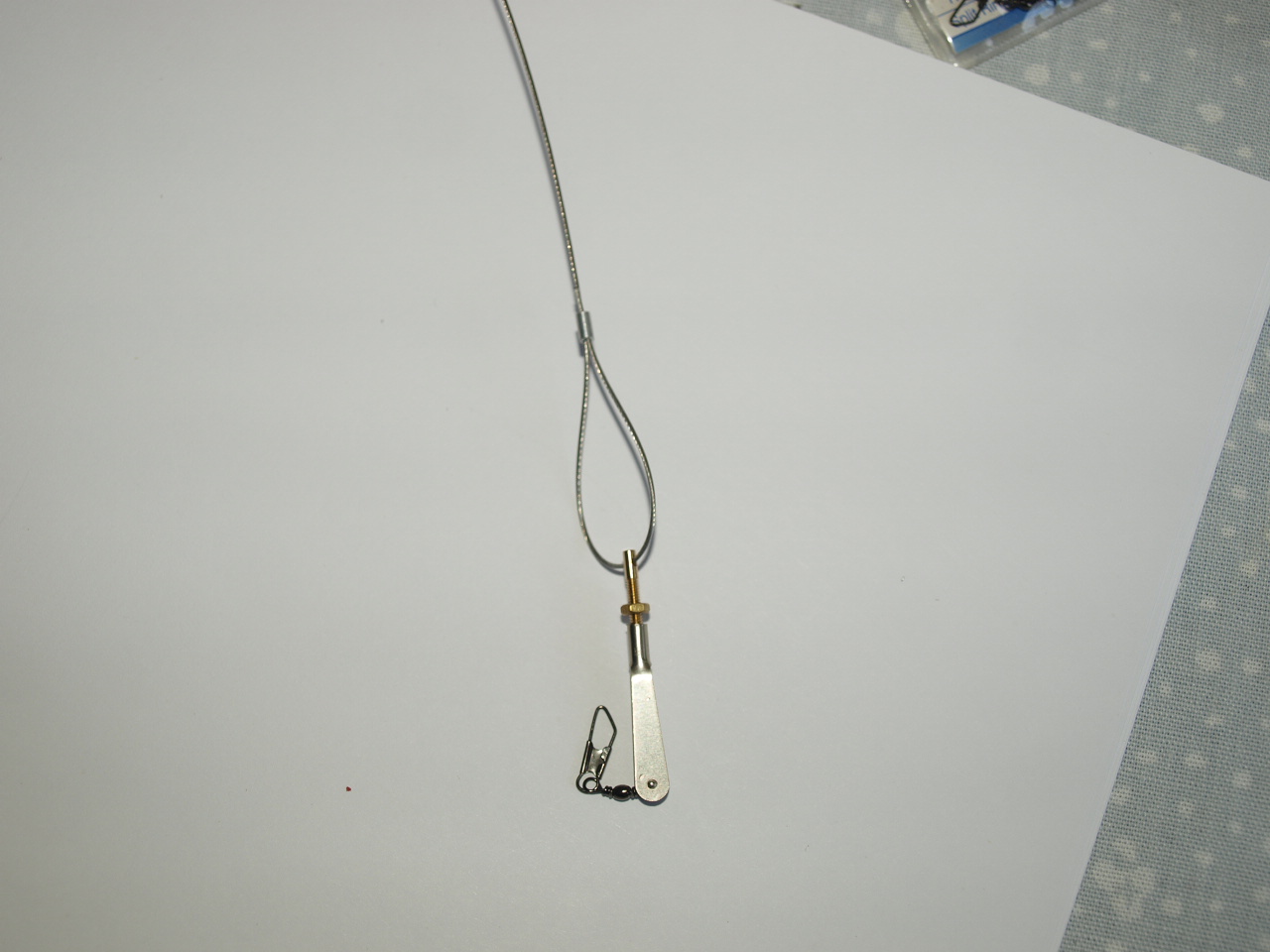
This picture showing the snap link and swivels joined
Rigging
Before I go any further, this is only a representation of the rigging on the Sopwith Pup and is not being presented by any means as a 100% scale rigging representation.
The following is my method of applying rigging to this model which once in situ gives a reasonable representation to that of the full sized aircraft.
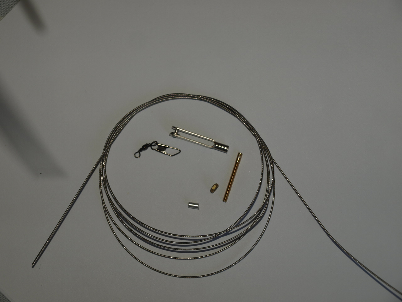
The first picture below shows the items that I will be using to make up the rigging.
Closed loop trace 75lb
M2 snap metal link
M2 closed loop adaptors
M2 brass nuts
Size 12 swivels with clip
Small aluminium tube
|
|
This picture showing the snap link and swivels joined |
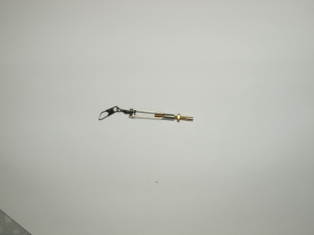 Next an M2 brass nut is threaded onto a closed loop adapter that is then in turn threaded onto the snap link
|
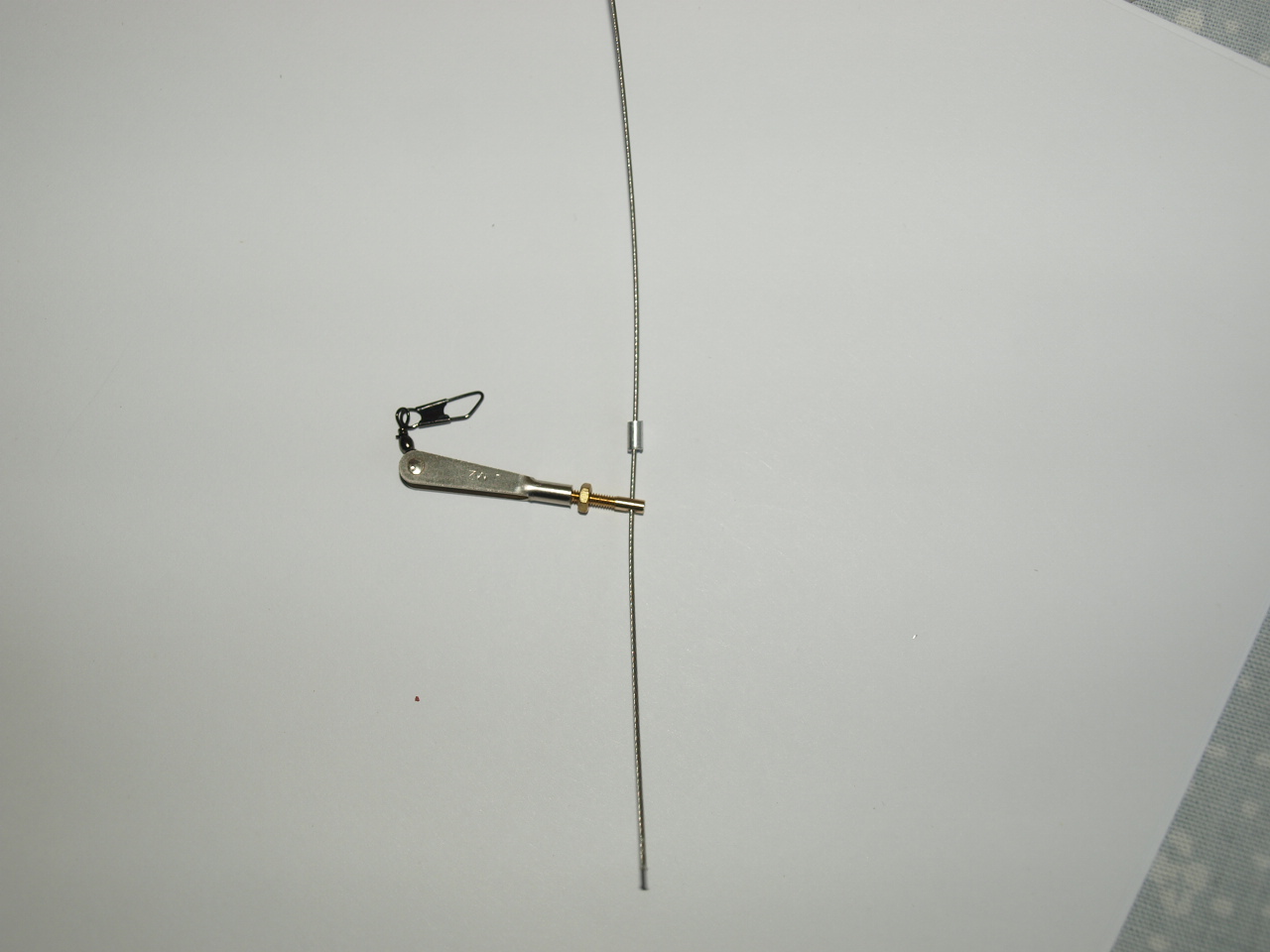 Next a small pre cut length of aluminium tube has the trace wire threaded through it. The wire is then threaded through the eyelet at the end of the adaptor. |
 The wire is then doubled back through the aluminium tube and pulled to form as small a loop as possible. Once completed the tube is crimped with a pair of pillars to prevent the wire from pulling back through |
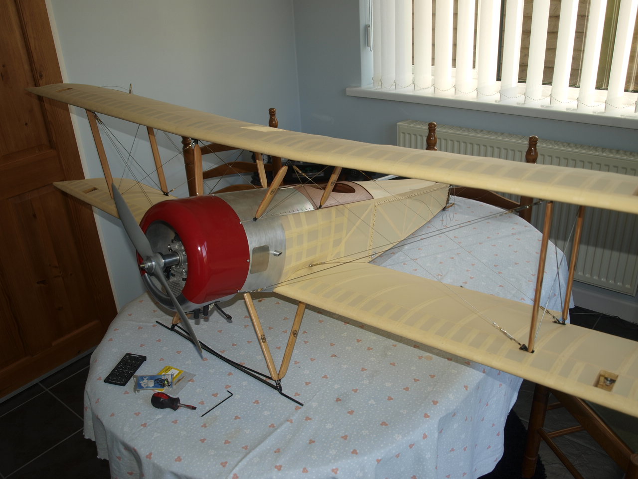
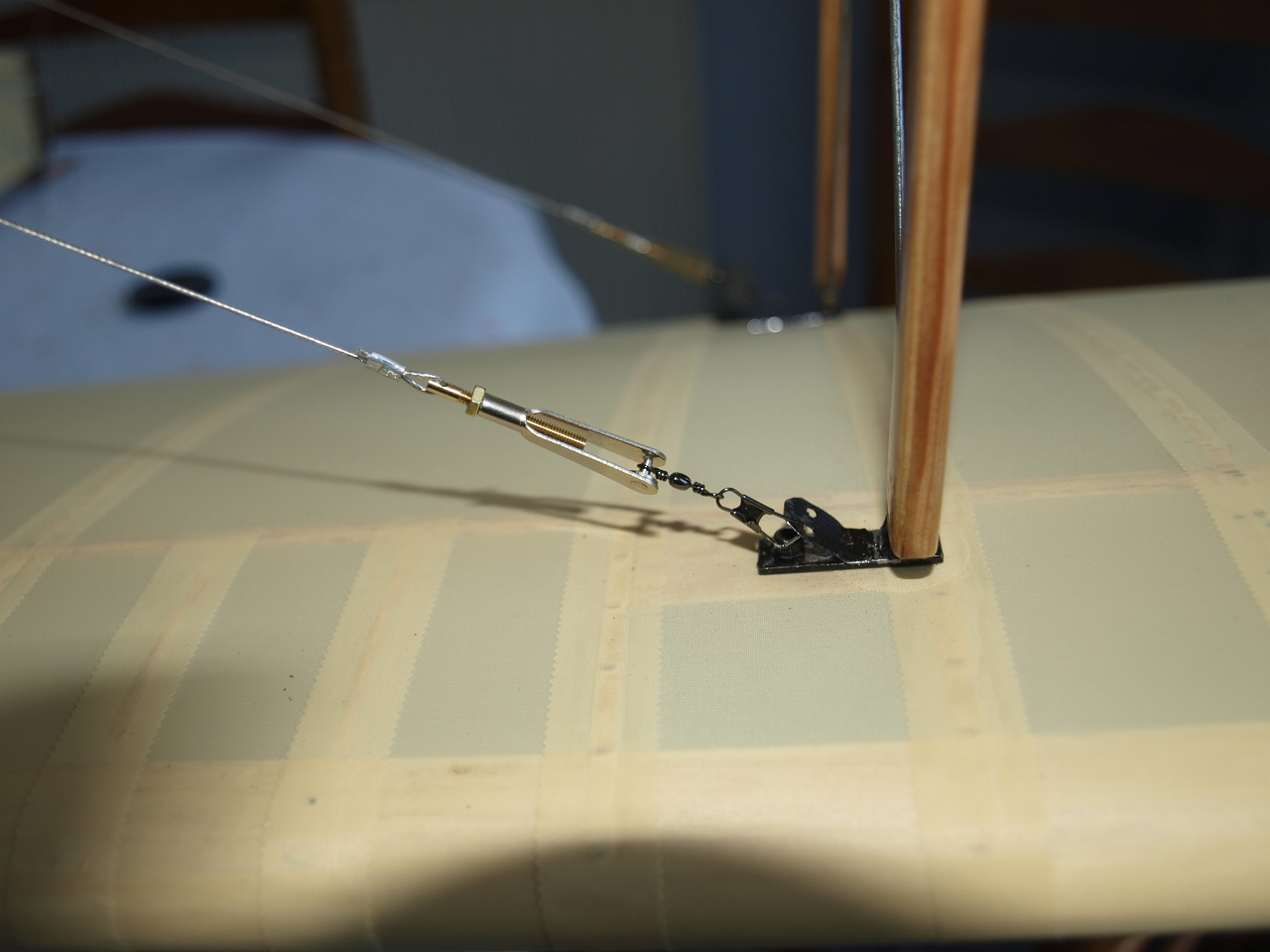 Once this assembly has been completed it is placed on the rigging anchors that have been soldered to the wing strut plates. With this end made up, the other end of the wire is made up in the same manner as just described but without the swivel. this time the snap link and adapter assembly directly placed in situ on the model before the wire is run to the required anchor point on the model. This allows the wire to be pulled to the correct length before crimping and cutting. Once you have completed this procedure the wires should be reasonably taught, but can be tensioned further by rotating the snap link until correct tension is achieved. All that is now required is to tighten the brass lock nuts to ensure that everything remains in place.
|
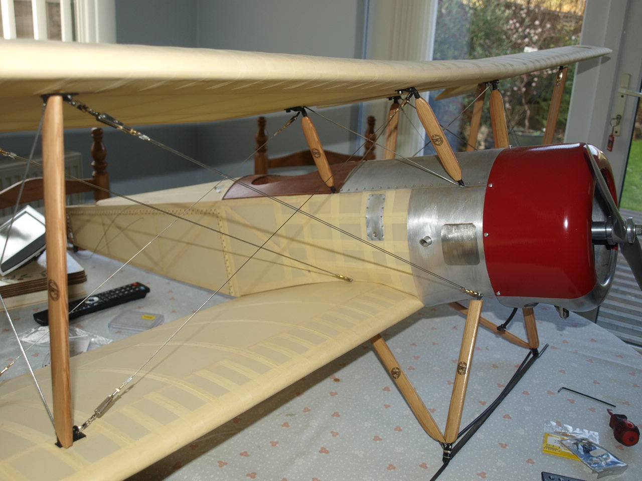
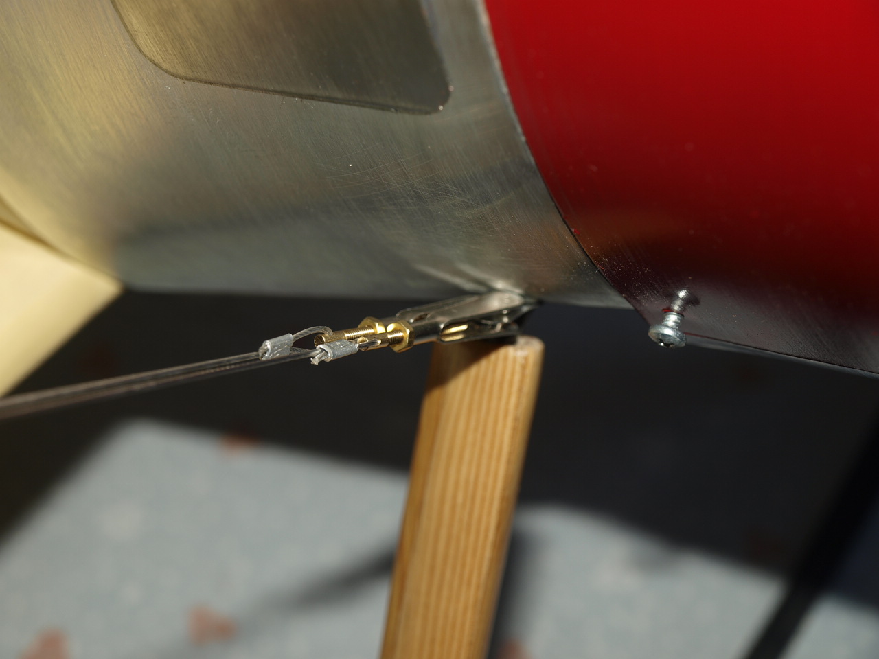 This picture and next, showing flying wires at fuselage. Note that as mentioned in the last picture no swivels have been used at these ends |
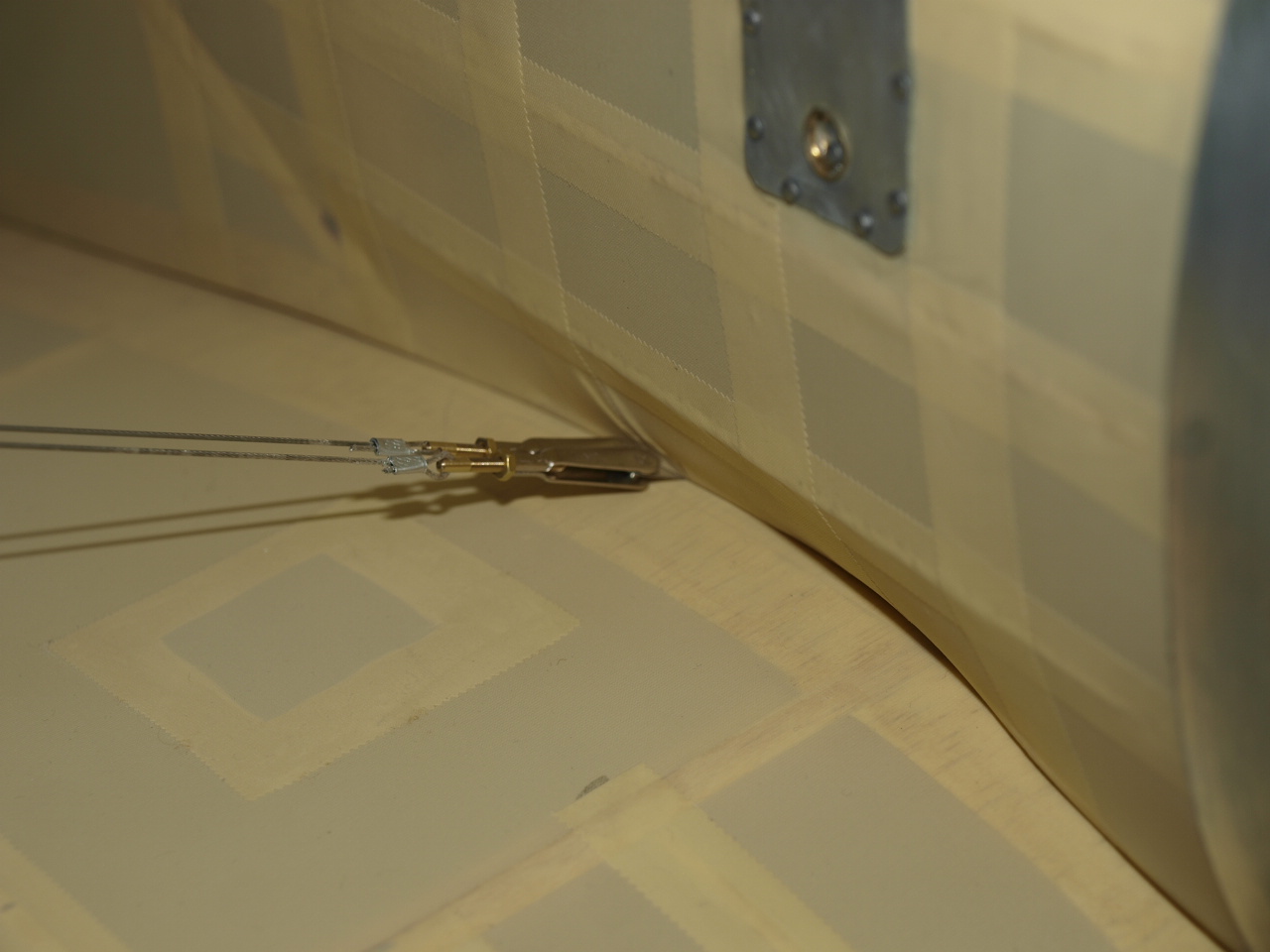 |
The final pictures below showing the now completed wing rigging. The wires coming from the top of the wing struts to the fuselage are the flying wires. (note that there are two wires coming from each strut.)
The wires coming from the top of the carbaine struts to the bottom of the wing strut are the landing wires (only one wire per strut)
 |
 |
Below rigging diagram used for wings
 |
Construction of Stabiliser
Construction of Rudder and Fin
Fuselage page
Struts &
Control Linkages
Construction of Wing
Aileron installation
Engine installation
Final Construction
Aluminium panels
Rib Tapes
Scale Detail